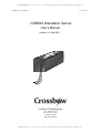
1
SUNSTAR传感与控制 http://www.sensor-ic.com/ TEL:0755-83376549 FAX:0755-83376182 E-MAIL:[email protected]
CXM544 User’s Manual
Version 1.4
CXM544 Orientation Sensor
User’s Manual
Revision 1.4 May 2001
Crossbow Technology Inc.
41 E. Daggett Drive
San Jose, CA 95134
(408) 965-3300
(408) 324-4840 Fax
Crossbow Technology, Inc.
Page 1
SUNSTAR自动化 http://www.sensor-ic.com/ TEL: 0755-83376489 FAX:0755-83376182 E-MAIL:[email protected]
SUNSTAR传感与控制 http://www.sensor-ic.com/ TEL:0755-83376549 FAX:0755-83376182 E-MAIL:[email protected]
CXM544 ORIENTATION SENSOR
Table of Contents
1. INTRODUCTION .........................................................................................................................................2
2. SYSTEM SPECIFICATIONS ..................................................................................................................... 3
3. MECHANICAL FEATUR ES .......................................................................................................................4
4. ELECTRICAL INTERFACE ......................................................................................................................4
5. INITIAL SETUP OF THE SYSTEM.........................................................................................................5
6. OPERATION OF THE SYSTEM ...............................................................................................................6
7. DESCRIPTIONS OF THE SYSTEM INTERNAL CONSTANTS ...................................................8
8. CHANGING THE BAUD RATE ................................................................................................................9
9. VERIFYING PROPER OPERATION OF THE SYS TEM .................................................................9
10. DETERMINING ORIENTATION ANGLES FROM 544 ACCELEROMETER AND
MAGNETOMETER DATA ....................................................................................................................10
10.1
10.2
10.3
10.4
10.5
10.6
SENSOR BASED COORDINATE SYSTEM ............................................................................................10
DEFINITION OF ORIENTATION A NGLES............................................................................................10
DEFINITIONS.........................................................................................................................................10
CALCULATION OF ROLL AND M AGNETIC ROLL.............................................................................11
CALCULATION OF INCLINATION .........................................................................................................12
M AGNETIC HEADING (A ZIMUTH, YAW ) ..........................................................................................12
11. USING THE 544TOOL SOFTWARE ...................................................................................................13
11.1BASIC DESCRIPTION ...............................................................................................................................13
11.2USING THE SOFTWARE ...........................................................................................................................13
11.3T ROUBLE ..................................................................................................................................................14
SUNSTAR自动化 http://www.sensor-ic.com/ TEL: 0755-83376489 FAX:0755-83376182 E-MAIL:[email protected]
SUNSTAR传感与控制 http://www.sensor-ic.com/ TEL:0755-83376549 FAX:0755-83376182 E-MAIL:[email protected]
CXM544 User’s Manual
Version 1.4
1. Introduction
The CXM544 Orientation Sensor system contains both a 3-axis fluxgate magnetometer and a
3-axis accelerometer. The combination of these two sensor systems enables the roll, pitch
and azimuth angles of the CXM544 reference frame with respect to the local gravity and
magnetic field vectors to be determined. Roll and pitch angles are determined from the accelerometer subsystem which measures the orientation of the system with respect to the
gravity vector. After roll and pitch are known, the magnetometer subsystem is used to determine the azimuth angle of the system. Knowledge of the roll and pitch angles enable determination of the horizontal components of the earth's local magnetic field; this information
defines the azimuth angle.
The CXM544 system also contains a microprocessor and 7 channel 16 bit analog to digital
converter. Six channels are assigned to the magnetometer and accelerometer outputs. One
channel provides temperature data from an internal thermometer. The functions performed
by the system microprocessor and A to D subsystem are: 1) conversion of the sensor analog
outputs to digital form; 2) calibration of the sensor scale, offset and alignment factors for a
temperature variation and 3) implementation of serial communications between the system
and an external computer.
The CXM544 communicates with the outside world over one of two serial bi-directional interfaces which can be selected from either TTL or RS232 voltage levels. An ASCII character
command language has been created to facilitate communication with the CXM544. For instance, if the ASCII characters for 0, S and D are sent in sequence, the CXM544 interprets
this as a "send data" command and responds by sending over the serial interface an ASCII
string representing the value of all magnetometer, accelerometer and temperature outputs.
The leading zero in this sequence denotes the system serial number. The CXM544 can also
be configured to send angle data (roll, pitch and azimuth) instead of the accelerometer and
magnetometer sensor data.
An auto send data mode is included in the CXM544 software. When this mode is active, data
is repeatedly sent after power is applied to the system at a rate of two transmissions per second in angular output mode and three times per second in magnetometer/accelerometer output mode.
The CXM544 system accelerometers are calibrated by placing the system in a precision rotation fixture and systematically changing the system orientation in the earth's gravitational
field. The CXM544 system magnetometers are calibrated by placing the system in a precision 3 axis Helmholtz coil system which enables the application of known magnetic fields to
the system. Both the rotation fixture and Helmholtz coil have alignment pins and reference
surfaces which mate to the CXM544 reference surface. System calibration can be performed
at a base temperature (usually 25°C) or over a temperature range (for example 15-90°C).
When the system is calibrated over a temperature range, data is read from the system at temperature intervals between the minimum and maximum temperature specification. For instance, for calibration over the interval of 15-90°C, data is usually read at 25°C temperature
intervals between 15° and 90°C. The data taken at each temperature includes scale, offset
and sensor alignment data. The recorded data is then used to create a look up table for scale
offset and alignment corrections. This table is then downloaded into the CXM544 internal
EEROM memory where it can be accessed by the system internal microprocessor. Corrections to the read sensor data can then be made by the internal microprocessor system before
data is transmitted.
Crossbow Technology, Inc.
Page 3
SUNSTAR自动化 http://www.sensor-ic.com/ TEL: 0755-83376489 FAX:0755-83376182 E-MAIL:[email protected]
SUNSTAR传感与控制 http://www.sensor-ic.com/ TEL:0755-83376549 FAX:0755-83376182 E-MAIL:[email protected]
CXM544 User’s Manual
Version 1.4
2. System Specifications
Angular Accuracy (0° to 70°C)
Azimuth:
Inclination:
Roll:
±1.5°
±0.5°
±0.5°
Temperature Range
Operating:
0° to 70°C )
Power
+5V ±0.05V @ 71 ma
or
+7 to +12V @ 71 ma
Size
0.75” x 0.80” x 4.6”
Shock
750 G 1ms half sine wave
Mass
50 grams
Vibration
Random vibrations 10G rms, 5-1000Hz
Digital Outputs
logic level
baud
protocol
TTL or RS232
user programmable up to 9600 baud
user selectable ASCII or binary
Leads
6” long flying leads
3. Mechanical Features
An outline drawing of the CXM544 system is shown in Figure 1. The system dimensions are
0.75" x 0.80" x 4.60" (1.90 cm x 2.03 cm x 11.68 cm). The system is normally mounted by
using 4 2-56 x 0.250 long screws to secure the CXM544 reference surface to a flat mating
surface. Two 0.062" dia x 0.125" long pins protruding from the external mating surface can
be used to orient the CXM544 on the external mounting surface. The orientation of the X
Y and Z axes is shown in Figure 1. The output polarity sense of the axes is such that a field
pointing in the direction of the arrows shown in Fig. 1 will produce a positive output voltage.
For example, if the X magnetometer is oriented so the X axis arrow points north, then the X
axis output voltage will be positive. If the X axis accelerometer arrow is pointed down, the X
axis accelerometer output will be positive.
Crossbow Technology, Inc.
Page 4
SUNSTAR自动化 http://www.sensor-ic.com/ TEL: 0755-83376489 FAX:0755-83376182 E-MAIL:[email protected]
SUNSTAR传感与控制 http://www.sensor-ic.com/ TEL:0755-83376549 FAX:0755-83376182 E-MAIL:[email protected]
CXM544 User’s Manual
0.067 diameter
2-56 Tapped Hole
0.200 deep
A
B
0.80”
(2 cm)
0.75”
(1.9 cm)
All dimensions in inches
Description
4.60”
(11.7 cm)
Hole
B
B
0.250
0.150 .002
0.150 .002
0.125
4.475” .003
(11.4 cm)
A
Version 1.4
Figure 1
Crossbow Technology, Inc.
Page 5
SUNSTAR自动化 http://www.sensor-ic.com/ TEL: 0755-83376489 FAX:0755-83376182 E-MAIL:[email protected]
SUNSTAR传感与控制 http://www.sensor-ic.com/ TEL:0755-83376549 FAX:0755-83376182 E-MAIL:[email protected]
CXM544 User’s Manual
Version 1.4
4. Electrical Interface
The electrical interface to the CXM544 system is shown in Figure 2. Seven flying leads (#26
gauge Teflon insulated) are used to make connection to the system. The functions of the output wires are shown in Figure 2. The CXM544 system can be powered either through an internal voltage regulator, which converts the input voltage to the +5 volts for internal use, or
from +5 VDC. When the input regulator is used, the input voltage can range from +7 to
+12V. An ideal input voltage which both provides adequate regulation margin and low
power consumption is +7.5V.
The serial communications interface to the CXM544 is provided by the serial in and seria l
out lines shown in Fig. 2. An external computer talks to the CXM544 on the serial in line
and replies from the CXM544 are transmitted out on the serial out line. The serial in and serial out lines operate at TTL or RS232 levels and are normally set to operate at 9600 baud
with one stop bit and no parity. The user however can change the baud rate by setting bits in
the system EEROM. (See Section 8)
Wire Color
Function
Red
+7 to +12 VDC
Black
Red/White
Ground
+5 VDC
Orange
RS232 serial in
Yellow
RS232 serial out
White/Orange
White/Yellow
TTL serial in
TTL serial out
Figure 2 Electrical Interface for Model 544 Sensor
Two communication protocols are available: 1) ASCII and 2) BINARY. The ASCII protocol is based upon sending ASCII characters to the CXM544 to obtain data. The CXM544
responds by sending out an ASCII data stream complete with carriage returns and line feeds
so that it can be easily displayed on a computer terminal. The binary protocol is used for
high speed computer to computer interchange. In this case, one byte is sent to request data
(e.g. ASCII 128). The CXM544 then responds with a data packet containing the desired data
plus header and checksum.
Crossbow Technology, Inc.
Page 6
SUNSTAR自动化 http://www.sensor-ic.com/ TEL: 0755-83376489 FAX:0755-83376182 E-MAIL:[email protected]
SUNSTAR传感与控制 http://www.sensor-ic.com/ TEL:0755-83376549 FAX:0755-83376182 E-MAIL:[email protected]
CXM544 User’s Manual
Version 1.4
The currently supported binary commands and their definitions follow:
Command
Command Definition
128
send sensor data in binary format
129
send sensor data in IEEE 32 bit format
131
send angle data in binary format
132
send angle data in IEEE 32 bit format
The CXM544 response to these commands is of the following form:
<number of data bytes> <MX> <AX> <MY> <AY> <MZ> <AZ> <MT> <AT>
<0> <data check sum><end>
Refer to the next section of this manual (Heading Sensor Command Set) for a more detailed
discussion of the data format for binary transmissions.
5. Initial Setup of the System
In order to operate the CXM544, power must be applied to it and an interface with an external computer must be set up. Powering will depend upon whether the unit is using a +5V
supply or the internal regulators and powers from +7VDC to +12VDC. To ensure system
accuracy, the +5V powered system must be within ± 0.05V of +5V.
Connect the correct power lead to the selected supply voltage. (See Figure 2)
After powering, the system should consume about 71 ma of input current.
In order to set up a computer interface with the system, select the output protocol of the
CXM544. This can be either TTL or RS232. The TTL protocol is usually used in microprocessor to microprocessor communications. For this mode, the voltage levels for a 0 and 1 are
approximately ground and 5V. In the idle or marking state, the output level is +5V.
The RS232 protocol is used by using serial com ports. RS232 voltage levels for a 0 and a 1
are approximately -5V and +5V. In the idle or marking state, the -5V level is output.
About 1 second after power up, the CXM544 will send out a sign on message. This can be
observed with an oscilloscope as a series of transitions from +5 to 0V (TTL) or -5V to +5V
(RS232).
Since PC's use RS232 protocol, they can be directly connected to a CXM544 employing this
protocol. PC's use either a 25 pin or a 9 pin D connector to implement their serial ports. This
connector is always a bulkhead male connector on the P.C. chassis. The serial in, serial out
and ground connections for these connectors are as follows:
Crossbow Technology, Inc.
Page 7
SUNSTAR自动化 http://www.sensor-ic.com/ TEL: 0755-83376489 FAX:0755-83376182 E-MAIL:[email protected]
SUNSTAR传感与控制 http://www.sensor-ic.com/ TEL:0755-83376549 FAX:0755-83376182 E-MAIL:[email protected]
CXM544 User’s Manual
Version 1.4
Function
25 pin
9 pin
serial out
2
3
serial in
3
2
ground
7
5
Connect the CXM544 serial output line to the computer in line and the CXM544 serial input
line to the computer serial out line.
To communicate with the CXM544, a terminal program will have to be run on the P.C. The
Windows HyperTerminal program will suffice for this. Other suitable terminal programs are
Procom and ASCII Pro. These programs turn the computer into a dumb terminal. In this
mode, whatever you type on the keyboard goes out the selected serial port (e.g. Com 1) and
whatever comes in the serial port is displayed on the computer video display.
If you use HyperTerminal, you must select the proper Com port (e.g. COM 1, COM 2, etc.)
and set the baud rate to be 9600 with one stop bit and no parity. Set the port up for direct
connect and turn off any handshaking.
The easiest method of determining if a working communications link with the CXM544 has
been established is to observe the P.C. display when the CXM544 is powered up. The
CXM544 transmits a power up sign on message which should appear in readable form on the
P.C. display. The appearance of an unreadable message at power up may indicate incorrect
protocol (i.e. TTL instead of RS232) or an incorrect baud rate.
6. Operation of the System
After establishing communication with the CXM544, data can be obtained from the system
by sending (typing) the command 0SD<CR> (0 Send Data). The 0 in this sequence is the default serial number of the unit. After sending this command, the CXM544 will respond with
an output that appears as follows:
MX: 0.5432
MY: 0.1234
MZ: 1.0145
t: 45.0
AX: 0.9456
AY: 0.4510
AZ: 0.0112
The numbers following the MX, MY and MZ headers represent the sensor magnetometer
output in Gauss. The numbers following the AX, AY and AZ headers represent the accelerometer output in gees. The temperature (°C) follows the t header.
The above outputs represent data sent when the CXM544 is in sensor mode. If angular data
is required, the system mode will need to be changed. In general, the CXM544 operating
characteris tics are controlled by the values of internal byte constants. These constants are
stored in the system EEROM and can be changed by a two step process. The two step process is used for security reasons to ensure that these constants are not inadvertently changed.
To change the CXM544 to angle mode, byte 02 must be changed from 02 (sensor mode) to
03 (angle mode).
Crossbow Technology, Inc.
Page 8
SUNSTAR自动化 http://www.sensor-ic.com/ TEL: 0755-83376489 FAX:0755-83376182 E-MAIL:[email protected]
SUNSTAR传感与控制 http://www.sensor-ic.com/ TEL:0755-83376549 FAX:0755-83376182 E-MAIL:[email protected]
CXM544 User’s Manual
Version 1.4
To accomplish this, type: 01<CR>
The unit will respond with the message: enabled!
Next, type the sequence: 0WC02b03<CR>
(0 Write Constant 02 byte 03)
The unit will respond by sending the message: done
Now request data by sending the sequence: 0SD<CR>
The response will look something like this:
MX: 180.0
MY: 90.3
MZ: 185.6
t: 24.3
AX: .6451
AY: .4056
AZ: 1.0001
The numbers following MX, MY and MZ represent the system roll, inclination and azimuth.
The numbers following the AX, AY and AZ represent the system magnetic roll angle, total
magnetic field and total gravitational field.
The total field numbers are of interest because they are the same for all orientations of the
sensor since
_____________
√ AX2 + AY2 + AZ2 = 1.0 Gee
______________
√ MX2 + MY2 + MZ2 = .5 Gauss
The degree to which these field magnitudes are constant for different orientations is a measure of the accuracy of the sensor. The actual magnetic field amplitude reported will vary
somewhat depending on location. This value ranges from 0.4 to 0.6 Gauss over the earth’s
surface.
It is also possible to configure the system mode to output raw A to D counts. This can be accomplished by setting byte 02=0.
In order to observe the value of any internal system constant send the commands
0SC02b <CR>
0SC*b <CR>
The first command results in the value of byte constant 02 being transmitted. The second
command evokes a response containing the values of all byte constants.
The CXM544 can transmit data in two formats: 1) text and 2) binary. Text transmissions are
formatted to display correctly when the CXM544 is connected to a PC running a terminal
emulator program (e.g. PC PLUS, HyperTerminal, etc.). Binary transmissions are faster than
text transmissions and are more suited to interfacing the CXM544 to a microprocessor system. In command mode, binary transmissions are initialed by sending a single byte to the
CXM544, e.g. ASCII 128 or ASCII 129.
The CXM544 has an autosend mode which enables data to automatically be sent repeatedly
Crossbow Technology, Inc.
Page 9
SUNSTAR自动化 http://www.sensor-ic.com/ TEL: 0755-83376489 FAX:0755-83376182 E-MAIL:[email protected]
SUNSTAR传感与控制 http://www.sensor-ic.com/ TEL:0755-83376549 FAX:0755-83376182 E-MAIL:[email protected]
CXM544 User’s Manual
Version 1.4
upon power up. Byte 01 must be set equal to 5A for autosend mode to be active. The format
of the data sent in autosend mode is determined by the value of byte 08. For repetitive text
transmissions, set byte 08=10. For repetitive binary transmissions, set byte 08=11.
7. Descriptions of the System Internal Constants
The CXM544 employs two types of internal constants: 1) byte and 2) floating. There are approximately 43 byte constants which are used to configure the operating characteristics of
the CXM544. The most important of these constants and their functions follow:
Detailed descriptions of all the internal byte constants can be found in the Appendix of this
manual.
Byte
Function
00
enables echoing when non zero
01
enables autosend when = 5A
02
enables sensor A/D count output when =0, sensor output when =02 and
angle output when =03
08
Sets power on mode (e.g., =10 enables autosend in ASCII mode on
power on)
09
Baud rate lock ( =5A if any baud rate other than 9600 is to be used)
10
Sets baud rate
8. Changing the Baud Rate
To change the communication baud rate from 9600 baud to any other rate, you must first
change byte constant 09 to 5A. Then, byte 10 can be set according to the fo llowing table:
Constant 10 value
Baud rate
35
300
33
1200
32
2400
31
4800
After setting byte 10, turn the power to the CXM544 off and on to set the new baud rate.
Note: When byte 09 is set to any value other than 5A, the system baud rate is
9600.
Crossbow Technology, Inc.
Page 10
SUNSTAR自动化 http://www.sensor-ic.com/ TEL: 0755-83376489 FAX:0755-83376182 E-MAIL:[email protected]
SUNSTAR传感与控制 http://www.sensor-ic.com/ TEL:0755-83376549 FAX:0755-83376182 E-MAIL:[email protected]
CXM544 User’s Manual
Version 1.4
9. Verifying Proper Operation of the System
Proper operation of the CXM544 can be verified when the system is in either angle mode
(byte 02=03) or sensor mode (byte 02=02).
In angle mode, proper operation is verified by placing the CXM544 in known orientations
and comparing the CXM544 measured data with the known orientation data.
To check roll and inclination outputs, place the CXM544 on a known flat surface with the Z
axis pointed down. A flat surface can be set up and verified by using a bubble level. Request
data from the CXM544 and verify that the roll and inclination outputs are as follows:
roll
inclination
0° ± 0.5°
90° ±0.5°
Next, roll the CXM544 about the X axis in increments of 90° and verify that for each position the roll angle increments in succession to 90°, 180° and 270° while the inclination angle
remains 90° ± 0.5°.
To verify inclination at 0° and 90°, position the CXM544 so that the X axis is pointed down
(0° inclination) and up (180°). Because the CXM544 leads exit the bottom of the unit when
the X axis is up, it may be awkward to verify this orientation without additional support
blocks.
To verify azimuth accuracy, a good compass and an area free from magnetic materials must
be located. Usually areas inside buildings contain some magnetic material (e.g. metal desks,
rebar in concrete floors, etc.). In this case, verifying azimuth accuracy to 1° is difficult.
Use a compass to orient the CXM544 approximately horizontal and East (inclination 90°,
azimuth 90°). Carefully align the CXM544 long (X) axis so that it is pointed East and verify
that the azimuth reading is 90° ±1.0°. Use the same procedure to verify azimuth accuracy for
180°, 270° and 0° readings.
In sensor mode (byte 02=02) the CXM544 accelerometer sensors should read +1.00 and 1.00 when pointed down and up respectively. Therefore when lying flat on a horizontal surface with the Z axis pointed down, the X and Y accelerometers should read 0±0.01 and the Z
accelerometer should read 1.00 ±0.01.
The CXM544 magnetometers are calibrated to read directly in Gauss. Proper operation of
these sensors is difficult to verify without elaborate calibration equipment. However, proper
“ballpark” verification of operation can be accomplished by pointing each magnetometer
sensor into and out of the earth’s magnetic field. For these orientations, the magnetometer
should read about +0.5G and -0.5G. In the Northern hemisphere, the direction of the earth’s
magnetic field is North with an inclination of about 60°. For instance, if the system X axis is
pointed to magnetic North and inclined about 60° into the earth, (30° from vertical) the X
magnetometer output should read +0.5 Gauss.
Crossbow Technology, Inc.
Page 11
SUNSTAR自动化 http://www.sensor-ic.com/ TEL: 0755-83376489 FAX:0755-83376182 E-MAIL:[email protected]
SUNSTAR传感与控制 http://www.sensor-ic.com/ TEL:0755-83376549 FAX:0755-83376182 E-MAIL:[email protected]
CXM544 User’s Manual
Version 1.4
10. Determining Orientation Angles from CXM544 Accelerometer and
Magnetometer Data
This application note describes how to calculate the roll, pitch and azimuth angles for the
CXM544 orientation sensor from accelerometer and magnetometer output data.
10.1 Sensor Based Coordinate System
The coordinate system of the CXM544 system is defined in Fig. 5. The accelerometer and magnetometer coordinate systems are both aligned with the physical package
coordinate systems shown. For the magnetometer sensors, a positive output voltage
will result if the sensor is pointed north. For the accelerometers, a positive voltage
will result if the sensors are pointed down.
10.2
Definition of Orientation Angles
The orientation angles are defined in Fig. 5 and 6. Azimuth or yaw is defined as the
angle measured from magnetic north (clockwise from above) to the projection of the
x axis on the horizontal plane.
Inclination is the angle that the x axis makes with the down direction and is 0 when
the x axis is down and 90° when the x axis is horizontal.
Roll or gravity tool face is defined as the angle of counterclockwise rotation about
the x axis (looking in the positive x axis direction) required to zero the y axis accelerometer output and position the z axis accelerometer so that its output polarity is positive.
Magnetic roll is defined as the angle of counterclockwise rotation about the x axis
(looking in the positive x axis direction) required to zero the y axis magnetometer
output and position the z axis magnetometer so that its output polarity is negative.
Magnetic roll is useful in defining the CXM544 orientation when inclination is near
vertical. In this situation, gy and gz are near zero and roll and azimuth calculations become less accurate.
10.3 Definitions
The following sections describe equations for determining the CXM544 orientation angles.
These equations make use of the following definitions:
gx accelerometer x axis output
gy accelerometer y axis output
gz accelerometer z axis output
Hx magnetometer x axis output
Hy magnetometer y axis output
Hz magnetometer z axis output
Crossbow Technology, Inc.
Page 12
SUNSTAR自动化 http://www.sensor-ic.com/ TEL: 0755-83376489 FAX:0755-83376182 E-MAIL:[email protected]
SUNSTAR传感与控制 http://www.sensor-ic.com/ TEL:0755-83376549 FAX:0755-83376182 E-MAIL:[email protected]
CXM544 User’s Manual
Version 1.4
N
Azimuth
E
Z
S
Y
X
Inclination
Down
Figure 5 - 544 Coordinate System
North
Magnetic Roll
30° as shown
UP
Roll
20° as shown
X
X
Y
544
Reference
Surface
Z
Wires
Y
544
Reference
Surface
Wires
Z
Figure 6 - 544 Orientation Angles
Crossbow Technology, Inc.
Page 13
SUNSTAR自动化 http://www.sensor-ic.com/ TEL: 0755-83376489 FAX:0755-83376182 E-MAIL:[email protected]
SUNSTAR传感与控制 http://www.sensor-ic.com/ TEL:0755-83376549 FAX:0755-83376182 E-MAIL:[email protected]
CXM544 User’s Manual
10.4
Version 1.4
Calculation of Roll and Magnetic Roll
The roll angle, θ, is determined by using the following equations
(0 < θ < 2 π):
gz
Cosθ =
Sinθ =
2
gy + gz
2
gy
g y + gz
Tan θ =
2
2
gy
gz
Roll is 0° when gy = 0 and gz > 0. Roll is 2π radians when gy = 0 and gz < 0. When
the X axis is near vertical (pitch < 5°), the quantities gy and gz become very small and
the above expressions yield a less accurate value of θ. In this situation, magnetic roll
is often used to determine the angular orientation of the CXM544 about the longitudinal (X) axis. Magnetic roll, θm, is given by the following
(0 < θm < 2π):
Sinθ m =
−Hy
Hy + Hz
Cosθ m =
Tan θ m =
Crossbow Technology, Inc.
2
2
− Hz
H y 2 + H z2
H
H
y
z
Page 14
SUNSTAR自动化 http://www.sensor-ic.com/ TEL: 0755-83376489 FAX:0755-83376182 E-MAIL:[email protected]
SUNSTAR传感与控制 http://www.sensor-ic.com/ TEL:0755-83376549 FAX:0755-83376182 E-MAIL:[email protected]
CXM544 User’s Manual
Version 1.4
10.5 Calculation of Inclination
Inclination, ε, is determined from the following equations
(0 < ε<π):
gx
g
Cos ε =
gy + gz
2
Sin ε =
2
g
gy2 + gz2
Tan ε =
gx
where g = g 2 + g 2 + g 2
x
y
z
Inclination is 0 when the CXM544 x axis is pointed down and π/2 radians when horizontal.
10.6
Magnetic Heading (Azimuth, Yaw)
We first give expressions for the magnetic field in a horizontal reference defined by
x1, y1, z1 where x1 is aligned with the projection of the CXM544 x axis in the horizontal plane and z1 is down.
H x1 =
H y1 =
Hz1 =
(
)
H x g y 2 + gz 2 − H y g y g x − H z g x gz
g gy2 + gz 2
H y g z − H zg y
gy + gz
2
2
Hx gx + Hygy +Hz gz
g
Magnetic heading , ø, is then given by (0 < ø <2π)
Cosφ =
Sinφ =
Crossbow Technology, Inc.
Hx 1
H x12 + H y12
− H y1
H x1 + H y1
2
2
Page 15
SUNSTAR自动化 http://www.sensor-ic.com/ TEL: 0755-83376489 FAX:0755-83376182 E-MAIL:[email protected]
SUNSTAR传感与控制 http://www.sensor-ic.com/ TEL:0755-83376549 FAX:0755-83376182 E-MAIL:[email protected]
CXM544 User’s Manual
Tanφ =
Version 1.4
− H y1
H x1
=
(
(H g
Hx gy + g
2
− H y g z )g
)− H g g
z y
2
z
y
x
y
− H z g x gz
Magnetic heading is 0 when the CXM544 x axis points North and π/2 radians when it points
East.
11.
Using The CXM544TOOL Software
11.1
Basic Description
This DOS program exercises the basic functions of the Model CXM544 Miniature Angular
Orientation Sensor and applies some post processing to the data. This program is not
shipped with the sensor, but can be provided upon request.
11.2
Using the Software
The compiled program is called CXM544TOOL.EXE. It requires one parameter - the comm
port number that the Position Sensor is connected to. For example, to select COM1, enter a
parameter of 1. To start the program from the command line, change the directory to where
the program is stored and enter CXM544TOOL followed by a space and then the com port
number. If there are no communication problems with the sensor, you will now see a screen
resembling the one shown in Fig. 4. If you don't see this but get a series of errors, and are
asked to enter a new port number or retry, go to the trouble section later in this description.
The sensor data screen is comprised of a status header, a data display area and a command
footer. The first line of the status header has the model number of the unit or APS if this is a
prototype. Next to this is the software version number of the software in the sensor. To the
right of this is a description of the corrections applied to the data (Raw Data, Scaled & Offset, Ortho Corrected, Angular Data, or Distance from Table). Next is the number of times the
data is averaged. On the far right is the display of the current reading of this average.
On the second line, the accumulated time since the Maximum, Minimum, and Noise data
was zeroed is displayed. Next to this is the number of readings taken in this time.
In the data area, there are four data sets. The first is the Current Data. This reflects the last
reading from the sensor averaged and corrected as reflected in the status line. The second
and third are the Maximum and Minimum Data areas. These areas record the largest and
smallest values seen in current data area. The last area is Noise. This reflects the difference
between the maximum and the minimum data areas. At the bottom of the screen is a list of
available commands.
These are:
Q
<Esc> Z
-
Quit Program.
Quit Program.
Zero (reset) maximum, minimum, and noise data areas.
Crossbow Technology, Inc.
Page 16
SUNSTAR自动化 http://www.sensor-ic.com/ TEL: 0755-83376489 FAX:0755-83376182 E-MAIL:[email protected]
Crossbow Technology, Inc.
Z:+25839.00000
Z:-25318.00000
Z:
Z:
Y:+25839.00000
Y:-25318.00000
Y:
Y:
+2.00000
+1.00000
Z:+25837.00000
Z:-25319.00000
Y:+25838.00000
Y:-25320.00000
+1.00000
+2.00000
Z:+25838.00000
Z:-25318.00000
Y:+25838.00000
Y:-25319.00000
T:
T:
+1.00
+2.00
T:+27112.00
T:+26788.00
T:+27111.00
T:+26786.00
T:+27112.00
T:+26786.00
Q or <ESC> - Quit / Z – Zero Max/Mins M – Inc Data Mode / ± Averaging
P – Print / W – Write to File / C – Constant Mode / H – Hold / K – XYZ Cal
Current Data:
MAG: X:+25838.00000
ACC: X:-25318.00000
Minimum Data:
MAG: X:+25838.00000
ACC: X:-25319.00000
Maximum Data:
MAG: X:+25839.00000
ACC: X:-25318.00000
Noise:
MAG: X:
+1.00000
ACC: X:
+1.00000
Model: APS 544
Ver: 1.032
Output is Raw Data in Counts Averaged 1 Times 00
Accumulation Time: 00:00:09 (Counts:14)
Figure 4 – Typical Screen Display
SUNSTAR传感与控制 http://www.sensor-ic.com/ TEL:0755-83376549 FAX:0755-83376182 E-MAIL:[email protected]
CXM544 User’s Manual
Version 1.4
Page 17
SUNSTAR自动化 http://www.sensor-ic.com/ TEL: 0755-83376489 FAX:0755-83376182 E-MAIL:[email protected]
SUNSTAR传感与控制 http://www.sensor-ic.com/ TEL:0755-83376549 FAX:0755-83376182 E-MAIL:[email protected]
CXM544 User’s Manual
M
-
+
P
W
H
K
-
C
-
11.3
Troubleshooting
Version 1.4
Increment data correction mode from raw to scaled to
final corrected to angular data.
Add one to the number of averages done on data.
Subtract one from the number of averages done on data.
Print the Current Data, Maximums, Minimums, and Noise.
Write the Current Data to a data file.
Hold the display and the program until a key is pressed.
Start the process of requesting and reading calibration data.
(See the Calibration section for more information)
Change to a mode for displaying, storing, and changing
constants internal to the sensor. (At the current time, few of these
constants are used, and those that are preset to their correct values
so this mode is of little use.)
If after starting the software you get a series of error messages rather than the data screen,
wait for about twenty seconds. You will be asked to enter a new serial port. Enter a new com
port number and press return to retry or press escape to exit.
If you have a communication error, this can be caused by:
Problem Indication
The sensor’s power is off
The serial cable is unplugged
Solution
Turn the sensor on and press return
Plug it in and press return
The wrong serial port number was
used
Enter the correct poet number and
press return
The cable is wired incorrectly (The
sensor is configured as a DTC device
and so requires a null modem or a cable that reverses 2 & 3 between it and
your computer)
Correct the cable or install a null
modem and press return
Your P.C. serial port is non-standard
or not configured as COM1 or COM2
Configure your port as COM1 or
COM2 and your interrupt as INT 3 or
INT 4
If the program starts fine but then locks up or displays errors on the screen, you may have a
loose connection in your serial cable or at the connector, you may require a shielded cable or
your cable may be too long (less than 25' are recommended).
Crossbow Technology, Inc.
Page 18
SUNSTAR自动化 http://www.sensor-ic.com/ TEL: 0755-83376489 FAX:0755-83376182 E-MAIL:[email protected]
SUNSTAR传感与控制 http://www.sensor-ic.com/ TEL:0755-83376549 FAX:0755-83376182 E-MAIL:[email protected]
CXM544 User’s Manual
Version 1.4
Heading Sensor Command Set
CXM544
V3.18DFX 1/00
544
Addressed Command is : <Address><Command><CR>
An Address is <0-9 | A-Z>
CR is a Carriage Return
Axis is <X - Z | T>
Constant Number is <00 - 99>
Constant Value is <[-]<number>[.<number>]>
Constant String is <A-Z | 0-9><Constant String>
A number is <<0-9>[number]>
A command consists of one of the following:
Send All Data
: SD All Data is sent
as requested,
raw, vectors or
angles as set by
byte constant 2
MX: ±#.##### AX:±#.#####<CR><LF>
MY: ±#.##### AY:±#.#####<CR><LF>
MZ: ±#.##### AZ:±#.#####<CR><LF>
MT: ±###.####<CR><LF>
AT: ±###.####<CR><LF><EOT>
Send Ana1 Input
: SA ANA: #.#####<CR><LF><EOT>
Read Float Constant
: SC<Constant Number>F ±########±E##<CR><LF><EOT>
Read All Float Constants
: SC*F
Read Byte Constant
: SC<Constant Number>B ##<CR><LF><EOT> (In Hex)
Read All Byte Constants
: SC*B 00: ##<CR><LF> (In Hex)
01: ##<CR><LF><EOT>
...
##: ##<CR><LF><EOT>
Read int Constant
: SC<Constant Number>I
Read all int Constants
: SC*I
Crossbow Technology, Inc.
00: ±########±E##<CR><LF>
01: ±########±E##<CR><LF>
...
##: ±########±E##<CR><LF><EOT>
#####<CR><LF><EOT>
00: #####<CR><LF>
01: #####<CR><LF><EOT>
...
##: ##<CR><LF><EOT>
Page 19
SUNSTAR自动化 http://www.sensor-ic.com/ TEL: 0755-83376489 FAX:0755-83376182 E-MAIL:[email protected]
SUNSTAR传感与控制 http://www.sensor-ic.com/ TEL:0755-83376549 FAX:0755-83376182 E-MAIL:[email protected]
CXM544 User’s Manual
Version 1.4
Reset A/D
: RA
Done<CR><LF><EOT>
Test ROM Checksum(*)
: TC if low level writes are
enabled, the output is: STORED HHHH<CR><LF><EOT>
If low level writes are
not enabled and the
Checksum of the ROM is
the same as the one
stored:
HHHH<CR><LF><EOT>
else the Output is:
ERR HHHH<CR><LF><EOT>
Test EEROM Checksum(*) : TE if low level writes are
enabled, the output is: STORED HHHH<CR><LF><EOT>
If low level writes are
not enabled and the
Checksum of the ROM is
the same as the one
stored:
HHHH<CR><LF><EOT>
else the Output is:
ERR HHHH<CR><LF><EOT>
Test RAM
: TR Either an OK or an error OK<CR><LF><EOT>
The Error Addr. is in Hex
ERR AT: HHHH<CR><LF><EOT>
Test EEROM Read/Write*
: TW (This takes up to 10 Secs.)
Either an OK or an error OK<CR><LF><EOT>
The Error Addr. is in Hex
ERR AT: HHHH<CR><LF><EOT>
Test Serial Port
: TS
Return Software Version
: TV
Ver: #.###<CR><LF><EOT>
Enable Low Level Writes
:L
Enabled!<CR><LF><EOT>
Always Echoes
OK<CR><LF><EOT>
Write Float To Constant*: WC<Constant Number>F<Value> Done<CR><LF><EOT>
Write Byte To Constant*: WC<Constant Number>B<number> Done<CR><LF><EOT>
Crossbow Technology, Inc.
Page 20
SUNSTAR自动化 http://www.sensor-ic.com/ TEL: 0755-83376489 FAX:0755-83376182 E-MAIL:[email protected]
SUNSTAR传感与控制 http://www.sensor-ic.com/ TEL:0755-83376549 FAX:0755-83376182 E-MAIL:[email protected]
CXM544 User’s Manual
Version 1.4
Write Int To Constant*: WC<Constant Number>B<number> Done<CR><LF><EOT>
* All Commands marked with an * require the Enable Low Level Writes command to be executed as the previous command for successful execution.
All Commands Marked with a (*) execute differently when Enable Low Level Writes was executed as the previous command.
----- Binary Commands ----<128> Send All Data as Vectors in a Binary Format.
<129> Send All Data as Vectors in a IEEE Float Format.
<131> Send All Data as Angles in a Binary Format
<132> Send All Data as Angles in a IEEE Float Format
<128> and <131>
Sends All Data in an encoded Binary Format in the
current format as selected by Byte constant #2.
If the correction mode is 0, 1 or 2 the data is
returned as:
<<<<Sent First <<<<<<<<<<<<<<<<<<<<<<<<<<<<<<<<<<<<<<<<<<<Sent Last<<<<
If The Command is 128:
<NUMDATABYTES><MX><AX><MY><AY><MZ><AZ><MT><AT><0><DATACHKS
UM><END>
size
8b
16b 16b 16b 16b 16b 16b 16b 16b 8b
8b
16b
in bits
If The Command is 131:
<NUM DATA
BYTES><Roll><MRoll><Pitch><Mag><Head><Grav><MT><AT><0><DATA CHK
SUM><END>
size
8b
16b
16b 16b 16b
16b 16b 16b 16b 8b
8b
16b
in bits
<END>
= 0x7FFF (is unique in the data stream)
<NUM DATA BYTES>
= 16
<0>
= a constant 0 (to allow END to be unique)
<DATA CHECK SUM>
= The lower 8 bits of the sum of all the bytes
in the data area.
<Roll>
= The Roll data encoded as below.
<Pitch>
= The Pitch data encoded as below.
<Head>
= The Heading data encoded as below.
Crossbow Technology, Inc.
Page 21
SUNSTAR自动化 http://www.sensor-ic.com/ TEL: 0755-83376489 FAX:0755-83376182 E-MAIL:[email protected]
SUNSTAR传感与控制 http://www.sensor-ic.com/ TEL:0755-83376549 FAX:0755-83376182 E-MAIL:[email protected]
CXM544 User’s Manual
Version 1.4
<MRoll>
<Mag>
= The Magnetic Roll data encoded as below.
= The Total Magnetic Field data encoded as
below.
<Grav>
= The Total Gravitational Field data encoded as
below.
<MX>,<MY>,<MZ> = The Mag. data encoded as below.
<AX>,<AY>,<AZ> = The Acc. data encoded as below.
<MT>,<AT>
= The Temp data encoded as below.
All data is sent most significant byte first.
If the correction mode is 0, the Mag and Acc data is in a
two byte signed integer format in counts.
If the correction mode is 1 or 2, the Mag and Acc data is in a
two byte signed integer format encoded as the float value
times 10000. (1.2345 = 12345)
If the correction mode is 3 the data is angles and is represented
in a two byte signed integer format encoded as the float value
times 10. (123.45 = 1234)
The Temp data is in a two byte signed integer format encoded
as the float value times 100. (123.45 = 12345)
<129>and <132>
Sends All Data in IEEE Floating point format in the current format as selected by Byte constant #2.
If the correction mode is 0, 1 or 2 the data is
returned as:
<<<<Sent First<<<<<<<<<<<<<<<<<<<<<<<<<<<<<<<<<<<<<<<<<<<<Sent Last<<<<
If The Command is 129:
<NUM DATA BYTES><MX><AX><MY><AY><MZ><AZ><MT><AT><0><DATA
CHECK SUM>
size
8b
32b 32b 32b 32b 32b 32b 32b 32b 8b
8b
in bits
If The Command is 132:
<NUM DATA
BYTES><Roll><MRoll><Pitch><Mag><Head><Grav><MT><AT><0><DATA CHECK
SUM>
size
8b
32b 32b
32b 32b 32b 32b 32b 32b 8b
8b
in bits
<END>
= 0x7FFF (is unique in the data stream)
<NUM DATA BYTES>
= 16
Crossbow Technology, Inc.
Page 22
SUNSTAR自动化 http://www.sensor-ic.com/ TEL: 0755-83376489 FAX:0755-83376182 E-MAIL:[email protected]
SUNSTAR传感与控制 http://www.sensor-ic.com/ TEL:0755-83376549 FAX:0755-83376182 E-MAIL:[email protected]
CXM544 User’s Manual
<0>
<DATA CHECK SUM>
<Roll>
<Pitch>
<Head>
<MRoll>
<Mag>
<Grav>
<MX>,<MY>,<MZ>
<AX>,<AY>,<AZ>
<MT>,<AT>
Version 1.4
= a constant 0 (to allow END to be unique)
= The lower 8 bits of the sum of all the bytes
in the data area.
= The Roll data.
= The Pitch data.
= The Heading data.
= The Magnetic Roll data.
= The Total Magnetic Field data.
= The Total Gravitational Field data.
= The Mag. data.
= The Acc. data.
= The Temp data.
All data is sent most significant byte first.
Ortho Constants are designated Result Axis first, Component Axis Second.
----- Float Constant Numbers and Their Meanings ----00 - Ana1 Scale
01 - Temp Scale
02 - Ana1 Offset
03 - Temp Offset
04 - Mag Base Offset X
05 - Mag Base Offset Y
06 - Mag Base Offset Z
07 - Acc Base Offset X
08 - Acc Base Offset Y
09 - Acc Base Offset Z
10 - Mag Base Scale X
11 - Mag Base Scale Y
12 - Mag Base Scale Z
13 - Acc Base Scale X
14 - Acc Base Scale Y
15 - Acc Base Scale Z
16 - Mag Scale2 X
17 - Mag Scale2 Y
18 - Mag Scale2 Z
19 - Acc Scale2 X
20 - Acc Scale2 Y
21 - Acc Scale2 Z
22 - Mag Base Ortho(X,X)
23 - Mag Base Ortho(X,Y)
24 - Mag Base Ortho(X,Z)
25 - Mag Base Ortho(Y,X)
Crossbow Technology, Inc.
Page 23
SUNSTAR自动化 http://www.sensor-ic.com/ TEL: 0755-83376489 FAX:0755-83376182 E-MAIL:[email protected]
SUNSTAR传感与控制 http://www.sensor-ic.com/ TEL:0755-83376549 FAX:0755-83376182 E-MAIL:[email protected]
CXM544 User’s Manual
Version 1.4
26 - Mag Base Ortho(Y,Y)
27 - Mag Base Ortho(Y,Z)
28 - Mag Base Ortho(Z,X)
29 - Mag Base Ortho(Z,Y)
30 - Mag Base Ortho(Z,Z)
31 - Acc Base Ortho(X,X)
32 - Acc Base Ortho(X,Y)
33 - Acc Base Ortho(X,Z)
34 - Acc Base Ortho(Y,X)
35 - Acc Base Ortho(Y,Y)
36 - Acc Base Ortho(Y,Z)
37 - Acc Base Ortho(Z,X)
38 - Acc Base Ortho(Z,Y)
39 - Acc Base Ortho(Z,Z)
40 - Bow Correction X
41 - Bow Correction Y
42 - Bow Correction Z
----- Byte Constant Numbers and Their Meanings ----00 - Command Echo Flag. 0 is no command echo; anything else, echo commands
01 - Autostart Flag. If 0x5A executes the selected autostart option on
powerup.
02 - Correction Level 0- Raw / 2- Vectors / 3- Angles
In Angles mode, Roll is labeled MX, Pitch is labeled MY, Heading is
Labeled MZ, Mag. Roll is labeled AX, Total Mag Field is labeled AY,
Total Grav. Field is labeled AZ.
03 - Months since 1/90 when device was calibrated
04 - Version of the Calibration Software used
05 - Power on self test flag. If zero, a self test will be done on power
up.
06 - Enable extended error messages
07 - This Sensor's Address Number 0-36 => 0-9,A-Z
08 - Auto Start Mode, on powerup start accepting commands then:
0x00: Send all data in text mode once.
0x01: Send all data In Binary mode once.
0x02: Send all data In IEEE mode once.
0x10: Send all data in text mode a loop until AutoStart is not 0x5A.
0x11: Send all data In Bin. mode in a loop until AutoStart is not 0x5A.
0x12: Send All Data In IEEE mode in a loop until AutoStart is not 0x5A.
09 - User power on baud rate lock (if not 0x5A sensor will use 9600 Baud).
10 - User power on baud rate. --Use With Caution--
Crossbow Technology, Inc.
Page 24
SUNSTAR自动化 http://www.sensor-ic.com/ TEL: 0755-83376489 FAX:0755-83376182 E-MAIL:[email protected]
SUNSTAR传感与控制 http://www.sensor-ic.com/ TEL:0755-83376549 FAX:0755-83376182 E-MAIL:[email protected]
CXM544 User’s Manual
Target
Baud
75
150
300
600
Version 1.4
Const
#10
37
36
35
34
Target
Baud
1200
2400
4800
9600
Const
#10
33
32
31
30
11 - Not Used
12 - Lowest Calibration Temp. in counts. LSB
13 - Lowest Calibration Temp. in counts. MSB
14 - Distance in counts between Calibration Points LSB
15 - Distance in counts between Calibration Points MSB
16 - Number of Temp. Points in the SEEROM.
17 - The Table Mag Offset Scale Value.
(Offset = TableOffset / 2^<Byte#18>)
18 - The Table Acc Offset Scale Value.
(Offset = TableOffset / 2^<Byte#19>)
19 - The Table Mag Scale Scale Value. (Scale = TableScale / 2^<Byte#20>)
20 - The Table Acc Scale Scale Value. (Scale = TableScale / 2^<Byte#21>)
21 - The Table Mag Ortho Scale Value. (Ortho = TableOrtho / 2^<Byte#22>)
22 - The Table Acc Ortho Scale Value. (Ortho = TableOrtho / 2^<Byte#23>)
23 – Not Used
24 - Product I.D. String char #1
25 - Product I.D. String char #2
26 - Product I.D. String char #3
27 - Product I.D. String char #4
28 - Product I.D. String char #5
29 - Product I.D. String char #6
30 - Product I.D. String char #7
31 - Product I.D. String char #8
32 - Product I.D. String char #9
33 - Product I.D. String char #10
34 - Constant 0
35 - RTS Delay is the time in ~2 millisecond units that the RTS line is
high before data is sent. Any value but 0 will slow the data rate by
the same amount.
Crossbow Technology, Inc.
Page 25
SUNSTAR自动化 http://www.sensor-ic.com/ TEL: 0755-83376489 FAX:0755-83376182 E-MAIL:[email protected]
SUNSTAR传感与控制 http://www.sensor-ic.com/ TEL:0755-83376549 FAX:0755-83376182 E-MAIL:[email protected]
SUNSTAR 商斯达实业集团是集研发、生产、工程、销售、代理经销 、技术咨询、信息服务等
为一体的高科技企业,是专业高科技电子产品生产厂家,是具有 10 多年历史的专业电子元器件
供应商,是中国最早和最大的仓储式连锁规模经营大型综合电子零部件代理分销商之一,是一家
专业代理和分銷世界各大品牌 IC 芯片和電子元器件的连锁经营綜合性国际公司,专业经营进口、
国产名厂名牌电子元件,型号、种类齐全。在香港、北京、深圳、上海、西安、成都等全国主要
电子市场设有直属分公司和产品展示展销窗口门市部专卖店及代理分销商,已在全国范围内建成
强大统一的供货和代理分销网络。 我们专业代理经销、开发生产电子元器件、集成电路、传感
器、微波光电元器件、工控机/DOC/DOM 电子盘、专用电路、单片机开发、MCU/DSP/ARM/FPGA
软件硬件、二极管、三极管、模块等,是您可靠的一站式现货配套供应商、方案提供商、部件功
能模块开发配套商。商斯达实业公司拥有庞大的资料库,有数位毕业于著名高校——有中国电子
工业摇篮之称的西安电子科技大学(西军电)并长期从事国防尖端科技研究的高级工程师为您精
挑细选、量身订做各种高科技电子元器件,并解决各种技术问题。
更多产品请看本公司产品专用销售网站:
商斯达中国传感器科技信息网:http://www.sensor-ic.com/
商斯达工控安防网:http://www.pc-ps.net/
商斯达电子元器件网:http://www.sunstare.com/
商斯达微波光电产品网:HTTP://www.rfoe.net/
商斯达消费电子产品网://www.icasic.com/
商斯达实业科技产品网://www.sunstars.cn/
传感器销售热线:
地址:深圳市福田区福华路福庆街鸿图大厦 1602 室
电话:0755-83370250 83376489 83376549 83607652 83370251
传真:0755-83376182 (0)13902971329
邮编:518033
E-mail:[email protected]
82500323
MSN: [email protected]
QQ: 195847376
深圳赛格展销部:深圳华强北路赛格电子市场 2583 号 电话:0755-83665529
25059422
技术支持: 0755-83394033 13501568376
欢迎索取免费详细资料、设计指南和光盘 ;产品凡多,未能尽录,欢迎来电查询。
北京分公司:北京海淀区知春路 132 号中发电子大厦 3097 号
TEL:010-81159046 82615020 13501189838 FAX:010-62543996
上海分公司:上海市北京东路 668 号上海賽格电子市场 2B35 号
TEL:021-28311762 56703037 13701955389 FAX:021-56703037
西安分公司:西安高新开发区 20 所(中国电子科技集团导航技术研究所)
西安劳动南路 88 号电子商城二楼 D23 号
TEL:029-81022619 13072977981 FAX:029-88789382
SUNSTAR自动化 http://www.sensor-ic.com/ TEL: 0755-83376489 FAX:0755-83376182 E-MAIL:[email protected]