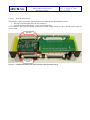
1
KECK NEXT GENERATION WAVEFRONT CONTROLLER
Real Time Controller
Maintenance Manual
Document :
Issue :
Date :
Prepared by :
Checked by :
NGWFC_RTC_MNT_MAN_001.doc
1
August 31st, 2007
MICROGATE
R.Biasi
D.Pescoller
M.Andrighettoni
..................................................
..................................................
..................................................
..................................................
Approved by :
..................................................
Released by :
..................................................
August 31st, 2007
Doc. :
Issue : 1 – August 31st, 2007
Page : 2 of 54
NGWFC
REAL TIME CONTROLLER
Maintenance Manual
CHANGE RECORDS
ISSUE
DATE
Author
1
22.09.2006
Microgate
Approved
QA/
QC
SECTION /
PARAG.
AFFECTED
All
REASON/INITIATION
DOCUMENTS/REMARKS
First Issue
NGWFC
REAL TIME CONTROLLER
Maintenance Manual
Doc. :
Issue : 1 – August 31st, 2007
Page : 3 of 54
TABLE OF CONTENTS
1
ACRONYMS ..............................................................................................................................7
2
APPLICABLE DOCUMENTS.................................................................................................9
3
REFERENCE DOCUMENTS ................................................................................................10
4
INTRODUCTION....................................................................................................................11
5
HARDWARE MAINTENANCE............................................................................................12
5.1
MVME CRATE HARDWARE MAINTENANCE ...........................................................12
5.1.1
POWER SUPPLY and FAN STATUS ........................................................................12
5.2
MGAOS CRATE HARDWARE MAINTENANCE .........................................................12
5.2.1
MGAOS crate replacement ........................................................................................12
5.2.2
MGAOS boards replacement .....................................................................................13
5.2.2.1 DSP boards.............................................................................................................14
5.2.2.2 BCU, WFS interface, DM interface.......................................................................15
5.2.2.2.1 WFS interface board ........................................................................................16
5.2.2.2.2 R DM interface board ......................................................................................17
5.2.2.3 HVC module ..........................................................................................................17
5.2.3
SCHEDULED MAINTENANCE ................................................................................18
5.3
TRS AND DISK ARRAY HARDWARE MAINTENANCE............................................18
6
SOFTWARE MAINTENANCE .............................................................................................19
6.1
MVME SOFTWARE MAINTENANCE...........................................................................19
6.1.1
Project Organization .................................................................................................19
6.2
MVME CONFIGURATION .............................................................................................20
6.3
MGAOS SOFTWARE.......................................................................................................20
6.3.1
DSP Software .............................................................................................................20
6.3.1.1 Project Organization ..............................................................................................20
6.3.1.2 Building the MGAOS projects...............................................................................22
6.4
TRS SOFTWARE ..............................................................................................................25
6.4.1
PostGre database.......................................................................................................25
6.4.1.1 Installation of PostgreSQL 8.1.3 on Solaris 10 1/06 .............................................25
6.4.2
Storage client ............................................................................................................27
6.4.2.1 Storage client installation......................................................................................27
6.4.2.2 General storage client operations...........................................................................28
6.4.2.3 Building the storage client software.......................................................................29
7
AUTOMATED SOFTWARE TEST PROCEDURES .........................................................30
7.1
TEST CONCEPT AND TEST TOOLS .........................................................................................30
7.2
SPECIFIC TEST TOOLS ..........................................................................................................32
7.2.1
AO library ..................................................................................................................32
7.2.2
WCI library ................................................................................................................34
7.2.3
TRS library.................................................................................................................34
7.2.4
CCD logic interface module ......................................................................................35
NGWFC
REAL TIME CONTROLLER
Maintenance Manual
Doc. :
Issue : 1 – August 31st, 2007
Page : 4 of 54
7.3
MATLAB TEST ROUTINES .....................................................................................................43
7.3.1
System setup ...............................................................................................................43
7.3.2
Matlab setup...............................................................................................................43
7.3.3
Structure of test procedures .......................................................................................43
7.3.4
Other Matlab utilities.................................................................................................44
8
MATLAB TOOLS TUTORIAL .............................................................................................45
8.1
MGP LOW LEVEL ROUTINES ................................................................................................45
8.2
AO HIGHER LEVEL ROUTINES ..............................................................................................46
8.3
DEBUGGING EXAMPLES .......................................................................................................50
8.4
HIGH SPEED DIAGNOSTIC BUFFERS ......................................................................................52
8.4.1
Using high speed diagnostic buffers with matlab ......................................................52
NGWFC
REAL TIME CONTROLLER
Maintenance Manual
Doc. :
Issue : 1 – August 31st, 2007
Page : 5 of 54
LIST OF FIGURES
Figure 1 - MGAOS crate....................................................................................................................13
Figure 2 – Installing/uninstalling the DSP board...............................................................................14
Figure 3 – Installing/uninstalling the BCU module. ..........................................................................15
Figure 4 – Installing/uninstalling the WFS interface board (AIA2PIO board). .......................16
Figure 5 – Installing/uninstalling the DM interface board (AIA2DM board)............................17
Figure 6 – Installing/uninstalling the HVC module...........................................................................18
Figure 7 - Project Options: Main menu .............................................................................................22
Figure 8 - Project Options: Compile General (1)...............................................................................22
Figure 9 - Project Options: Compile General (2)...............................................................................23
Figure 10 - Project Options: Link General.........................................................................................23
Figure 11 - Project Options: Link Elimination ..................................................................................24
Figure 12 - Project Options: Load Processor .....................................................................................24
Figure 13 – Test setup. Blocks in cyan represent dedicated components..........................................30
Figure 14 – Data flow in step mode and real-time mode. In real-time mode the verification is done
by post-processing the stored data. ............................................................................................31
Figure 15 - CCD interface scheme.....................................................................................................35
Figure 16 - internal registers of CCD interface module.....................................................................36
NGWFC
REAL TIME CONTROLLER
Maintenance Manual
Doc. :
Issue : 1 – August 31st, 2007
Page : 6 of 54
LIST OF TABLES
Table 1 – MVME CRATE COTS components documentation.........................................................12
Table 2 – MVME software organization ...........................................................................................19
Table 3 – MVME module organization .............................................................................................20
Table 4 - VisualDSP++ project group organization ..........................................................................21
Table 5 – List of AO library low level routines.................................................................................33
Table 6 – List of AO library high level routines................................................................................34
Table 7 – Automated Matlab system tests .........................................................................................44
NGWFC
REAL TIME CONTROLLER
Maintenance Manual
1 ACRONYMS
AO
Adaptive Optics
CCD
Charge Coupled Device
CIE
Command Interpreter and Executer
COTS
Commercial Off-The-Shelf
DDR
Double Data Rate
DM
Deformable Mirror
DMA
Direct Memory Access
DSP
Digital Signal Processor
DTT
Down Tip Tilt
DTTM
Down Tip Tilt Mirror
FCM
Fan Control Module
FC-IP
FibreChannel Internet Protocol
FITs
Number of Failures in 109 hours
FPDP
Front Panel Data Port
GPIB
General Purpose Interface Bus
HBA
Host Adapter Board
HP
Width unit for 19” chassis, corresponding to 0.2” (5.08mm)
HV
High Voltage
HVA
High Voltage Amplifier
HVC
High Voltage Control
ICMP
Internet Control Message Protocol
IIR
Infinite Impulse Response
LFpM
Linear Feet per Minute
LAN
Local Area Network
LGS
Laser Guide Star
LUT
Look Up Table
MAC
Multiply And Accumulate
mas
milliarcseconds
MGAOS
Microgate Adaptive Optics real-time System
MIMO
Multiple Input Multiple Output
MIL-STD military standard
MMF
Multi-Mode Fiber
NDA
Non Disclosure Agreement
NFS
Network File System
NGS
Natural Guide Star
NGWFC
Next Generation Wavefront Controller
PCB
Printed Circuit Board
Doc. :
Issue : 1 – August 31st, 2007
Page : 7 of 54
NGWFC
REAL TIME CONTROLLER
Maintenance Manual
PIO
Programmable Input Output
PSU
Power Supply Unit
RMS
Root-Mean-Square
RTC
Real Time Controller
SAN
Storage Area Network
SAS
Serial Attached SCSI
SCSI
Small Computer System Interface
SFP
Small Form factor Pluggable
SI
The International System of Units
SH
Shack-Hartmann
SRAM
Static Random Access Memory
SDRAM
Synchronous Dynamic Random Access Memory
STRAP
System for Tip-tilt Removal with Avalanche Photo-diodes
TBC
To Be Confirmed
TBD
To Be Defined
TRS
Telemetry Recorder/Server
U
Height unit for 19” chassis, corresponding to 1.75” (44.45mm)
UTT
Uplink Tip Tilt
UTTM
Uplink Tip Tilt Mirror
VME
VersaModule Eurocard
WBS
Work Breakdown Structure
WCP
Wavefront Controller Command Processor
WIF
Wavefront Controller Interface
WFP
Wavefront processor
WFS
Wavefront Sensor
Doc. :
Issue : 1 – August 31st, 2007
Page : 8 of 54
NGWFC
REAL TIME CONTROLLER
Maintenance Manual
Doc. :
Issue : 1 – August 31st, 2007
Page : 9 of 54
2 APPLICABLE DOCUMENTS
[AD1]
CARA/W.M. Keck
NGWFC RTC Requirements – Keck Adaptive optics note #311. Version 1.0, March 11th, 2005
[AD2]
CARA/W.M. Keck
NGWFC RTC Tip-Tilt Requirements – Keck Adaptive optics note #329. Version 1.0, May 25th,
2005
[AD3]
CARA/W.M. Keck
NGWFC RTC Vendor Statement of Work – Keck Adaptive optics note #310. Version 1.0, March
11th, 2005
[AD4]
CARA/W.M. Keck
NGWFC System Design Manual – Keck Adaptive optics note #289. Version 2.0, August 15th, 2005
[AD5]
Microgate S.r.l.
Real Time Controller ‘As-Built’ Design Review Data Package
Issue 1 – September 22nd, 2006
[AD6]
CARA/W.M. Keck
Request for change to the NGWFC RTC: Post PDR updates - Keck Adaptive optics note #354.
Version 1.4, Novemeber 3rd, 2005
[AD7]
CARA/W.M. Keck
NGWFC RTC Acceptance Test Plan - Keck Adaptive optics note #374
[AD8]
CARA/W.M. Keck
NGWFC Detailed Design Report - Keck Adaptive optics note #371
December 2nd, 2005
NGWFC
REAL TIME CONTROLLER
Maintenance Manual
Doc. :
Issue : 1 – August 31st, 2007
Page : 10 of 54
3 REFERENCE DOCUMENTS
[RD1]
R. Biasi, M.Andrighettoni et al. - ‘Dedicated flexible electronics for adaptive secondary control’, SPIE Proc. on ‘Advancements in Adaptive Optics’, 5490, p.1502
[RD2]
E-mails exchanged between Microgate and CARA-Keck between April 21st ad May 7th, 2005
[RD3]
Department of Defense USA, MIL-HDBK-217 Revision F, Reliability Prediction of Electronic
Equipment
[RD4]
Keck AO Wavefront Control –Hardware Manual
[RD5]
INCITS - FibreChannel – Physical and Signaling Interface – ANSI – INCITS 230-1994
[RD6]
M. Rajagopal, R. Bhagwat, W. Rickard - RFC 2625 - IP and ARP over FibreChannel - June 1999
NGWFC
REAL TIME CONTROLLER
Maintenance Manual
Doc. :
Issue : 1 – August 31st, 2007
Page : 11 of 54
4 INTRODUCTION
The NGWFC RTC maintenance manual covers both the HW and SW maintenance of the real time comtrol
system. The HW part provides the guidelines to perform ordinary maintenance operation on both the VME
and MGAOS crates, like boards substitution and periodic maintenance. The design aspects are not covered
by this manual, therefore for a deeper understanding of the design and functional aspects refer to [AD5].
The SW part of the manual provides an insight into the various project organization, including VME,
MGAOS and TRS software, and detailed instructions on how to rebuild the various projects.
A third part of the document is dedicated to the automated test procedures. Here we provide a thorough
description of the concepts behind the automated test tools and a list of the various test tools with indications
on how to use them. Finally, a tutorial on the available Matlab tools represents a valuable help to start using
the Matlab-based test and diagnostic routines.
NGWFC
REAL TIME CONTROLLER
Maintenance Manual
Doc. :
Issue : 1 – August 31st, 2007
Page : 12 of 54
5 HARDWARE MAINTENANCE
5.1
MVME CRATE HARDWARE MAINTENANCE
Within the system crate, the only parts subjected to mechanical stress are the cooling fans. Therefore it is
recommended to check periodically (indicatively every year) their functionality and to verify that the cooling
ducts are not obstructed by dust or other materials.
It is also recommended to check the PSU output voltages trimming every year.
The other components do not require scheduled maintenance. For more detailed information refer to the
manufacturer documentation of each component.
Component
Crate
MVME6100 board
Symmetricom TTM635VME irig board
Documentation
Crate.pdf
FCM Manual.pdf
Declaration of conformity.pdf
MVME6100 Single-Board Installation and Use
MVME6100 Single-Board Getting Started
MVME6100 Single-Board Programms’s Reference
Guide
TTM635VME/TTM350VXI User’s Guide
Table 1 – MVME CRATE COTS components documentation
5.1.1 POWER SUPPLY and FAN STATUS
The FAN status and power supply are monitored by the FCM module installed in the MVME Crate. The
FCM module provides the following information through 6 leds:
•
-12V green led: normally on, indicates -12V power supply is ok
•
+12V green led: normally on, indicates +12V power supply is ok
•
3.3V green led: normally on, indicates 3.3V power supply is ok
•
+5V green led: normally on, indicates 5V power supply is ok
•
FAN red led: normally off, lights in case of FAN failure
•
Over Temperature led: normally off lights in case of overtemperature
The FAN and Over Temperature alarms are also available as a digital output on the FCM module. For further
details please refer to FCM Manual.pdf
5.2
MGAOS CRATE HARDWARE MAINTENANCE
5.2.1 MGAOS crate replacement
All MGAOS components are hosted into a 6U, 44TE ‘subcrate’, which is mechanically compatible with
standard 19” 6U crates.
The procedure to uninstall the MGAOS crate is reported hereafter:
1. Shutdown the system
NGWFC
REAL TIME CONTROLLER
Maintenance Manual
Doc. :
Issue : 1 – August 31st, 2007
Page : 13 of 54
2. Switch off High Voltage power supply and crate power supply
3. Disconnect all connections on the front panel:
a. DM interface
b. WFS interface
c. STRAP sync signal
d. IRIG latch signal
e. FibreChannel connection to TRS
f.
Private Ethernet connection to MVME
g. DTT and UTT connections
4. Unscrew the four screws at the ‘subcrate’ edges
5. Extract the MGAOS ‘subcrate’ by pulling the handles
Extraction
handles
MGAOS boards
Locking screws
MGAOS subcrate
Locking screws
Figure 1 - MGAOS crate.
To re-install the MGAOS crate simply follow the above described procedure in reverse order.
5.2.2 MGAOS boards replacement
The MGAOS boards are mounted into the MGAOS ‘subcrate’ similarly to any other chassis-mounted
module, e.g. VME ones. The boards are inserted into a proprietary backplane with card edge connectors.
NGWFC
REAL TIME CONTROLLER
Maintenance Manual
Doc. :
Issue : 1 – August 31st, 2007
Page : 14 of 54
Important safety warning: before proceeding with the board(s) replacement, make sure that the main crate
power supply and the high voltage power supply are both switched off.
5.2.2.1 DSP boards
Installing and uninstalling the DSP boards does not require any
particular precaution.
To uninstall the DSP boards, simply unscrew the boards locking
screws (see Figure 1) and gently extract the board.
While installing the boards, they should slide into the crate with
moderate force. In case the board tends to stuck, re-extract it and
make sure there is no obstruction, like cables between the card
and the backplane connectors.
Important: the boards do not need any HW setup or
configuration. They are automatically detected and the address is
determined automatically based on their position on the
backplane.
Figure 2 – Installing/uninstalling the DSP board.
NGWFC
REAL TIME CONTROLLER
Maintenance Manual
Doc. :
Issue : 1 – August 31st, 2007
Page : 15 of 54
5.2.2.2 BCU, WFS interface, DM interface
The BCU module is placed at the left end of the MGAOS crate. It comprehends three boards, namely BCU,
AIA2PIO board acting as WFS interface and DM2PIO board, which is the interface to the DM HVA.
The BCU module can be uninstalled by releasing the boards locking screws and gently extracting it. Once
completely extracted, it is necessary to disconnect the reset connector from the DM2PIO board, as indicated
Figure 3.
Reset cable
and connector
Figure 3 – Installing/uninstalling the BCU module.
Installing the board, one should make sure that the reset cable is correctly positioned above the board so that
it does not interfere with the card edge connectors on the backplane.
NGWFC
REAL TIME CONTROLLER
Maintenance Manual
5.2.2.2.1
Doc. :
Issue : 1 – August 31st, 2007
Page : 16 of 54
WFS interface board
The hereafter reported procedure shall be followed to dismount the WFS interface board:
1. Disconnect the flat cable from the rear connector
2. Unlock the board releasing the screws on the front panel.
To re-install the WFS interface board on the BCU module simply follow the above described procedure in
reverse order.
Eject latch
Board holding
screws
Figure 4 – Installing/uninstalling the WFS interface board (AIA2PIO board).
Doc. :
Issue : 1 – August 31st, 2007
Page : 17 of 54
NGWFC
REAL TIME CONTROLLER
Maintenance Manual
5.2.2.2.2
R DM interface board
The hereafter reported procedure shall be followed to dismount the DM interface board:
1. Disconnect the reset connector
2. Disconnect the flat cable from the rear connector
3. Unlock the board releasing the screws on the front panel.
To re-install the WFS interface board on the BCU module simply follow the above described procedure in
reverse order.
Eject latch
Board holding
screws
Figure 5 – Installing/uninstalling the DM interface board (AIA2DM board).
5.2.2.3 HVC module
The HVC module can be uninstalled by releasing the boards locking screws and gently extracting it. Once
completely extracted, it is necessary to disconnect the High Voltage supply connector from the HVC analog
board, as indicated in. Once more we recommend to double check the high voltage power supply unit to be
off – shock hazard.
Re-installing the board, the high voltage supply connector shall be connected first. Before sliding the board
into the backplane, check that the high voltage cable does not interfere with the board edge connector. The
cable should be place over the top edge of the board, as indicated in Figure 6.
NGWFC
REAL TIME CONTROLLER
Maintenance Manual
High Voltage cable
and connector
Doc. :
Issue : 1 – August 31st, 2007
Page : 18 of 54
The High Voltage
cable shall be
positioned above
the board edge
Figure 6 – Installing/uninstalling the HVC module.
5.2.3 SCHEDULED MAINTENANCE
Within the system crate, the only parts subjected to mechanical stress are the cooling fans. Therefore it is
recommended to check periodically (indicatively every 6 months) their functionality and to verify the
presence of any obstruction (e.g. dust)
It is also recommended to check the PSU output voltages trimming every year.
5.3
TRS AND DISK ARRAY HARDWARE MAINTENANCE
The TRS server and the related Disk Array are off-the-shelf components. We recommend following the
maintenance instructions reported in the relevant manuals by the manufacturers: SurfRAID TRITON 16FA
User’s Manual and Sun Fire X4100 Server Setup Guide.
NGWFC
REAL TIME CONTROLLER
Maintenance Manual
Doc. :
Issue : 1 – August 31st, 2007
Page : 19 of 54
6 SOFTWARE MAINTENANCE
6.1
MVME SOFTWARE MAINTENANCE
6.1.1 Project Organization
The MVME software has been developed using Wind River Tornado 2.2.1
On top of the MVME software tree in the MVME6100 folder you will find the files/folders described in
Table 2
file/directory name
Irig
mgpDriver
Utility
Wif
Empty
mvme6100.wsp
Kernel
configuration
Init
keckStrapDriver
MGAOSCode
description
this is a software module for the irig timing board
this is the low level MGAOS communication module
this is a support module where certain utilities/tests are coded, this is used just for
development and could be removed
this is the main MVME module where all the high level functionalities are coded.
this is a dummy module structure it contains just the main subfolders doc, include and src
when a new module is created this is copied and renamed.
this is the MVME workspace file. In order to build the software open this file from
Tornado2.2 as workspace and the above modules should appear and you can compile them.
All module should compile without any warning with tornado 2.2.1, if this is not the case
something is wrong.
this is the VxWorks kernel, the boot parameters should be configured to load this kernel, this
could also be moved to an other place
this is the folder where the named configuration’s are loaded. At least one configuration file
named DEFAULT should be here. The configuration DEFAULT is automatically loaded at
each MGAOS reset
this directory contains the boot script which is called at the end of the VxWorks booting
sequence. This is configured in the boot parameters of VxWorks.
The other important file is the wifMGAOSBaseParameter.ini and its related data files. Here all
the base MGAOS parameters which are not changeable by the WIF interface are stored. These
parameters are supposed to be changed very rarely, but still sometimes, so they where not
built in to the code as “DEFINES”
this is the STRAP driver, this should probably be removed from here
this folder contains the MGAOS dsp codes (.ldr files), which are downloaded at each MGAOS
reset, there are three files one for each computational block:
CentroidCalculator.ldr
ResidualWavefrontCalculator.ldr
HVCController.ldr
Table 2 – MVME software organization
file/directory name
Doc
Src
Include
PPC604gnu
.wpj
prjObj.lst
Makefile
description
this is the documentation directory where a doxygen generation file is placed.
contains all the .c source files
contains all the .h declaration files
contains all the compiled modules and object files
is the tornado project file of the module
this is a support file for the Makefile used by the tornado build engine. Shortly it contains list
of all the .o files of the module
this is the Makefile; both the Makefile and prjObj.lst are automatically generated files
NGWFC
REAL TIME CONTROLLER
Maintenance Manual
Doc. :
Issue : 1 – August 31st, 2007
Page : 20 of 54
Table 3 – MVME module organization
6.2
MVME CONFIGURATION
The MVME6100 directory should be the base of a ftp server where the MVME6100 CPU can connect and
download files. Obviously it is possible also to have the MVME6100 folder not as the base for the ftp server
but some additional configuration work is needed, mainly in the boot script.
Hereafter we report an example of a working configuration:
boot device
: geisc
unit number
:0
processor number
host name
:0
: te101
file name
: kernel/default/vxWorks
inet on ethernet (e) : 192.168.0.126
inet on backplane (b): 192.168.1.125
host inet (h)
: 192.168.0.120
user (u)
: keck
ftp password (pw)
flags (f)
: diti24
: 0x8
target name (tn)
: dkvx11
startup script (s) : init/bootScript
6.3
MGAOS SOFTWARE
6.3.1 DSP Software
6.3.1.1 Project Organization
In the MGAOS system, all the computation is executed by the DSPs available in the BCU-COM, DSP-DO,
DSP-HVC boards. The DSP code has been developed using the VisualDSP++ 4.00.
The MGAOS system is structured in 3 different projects:
•
CentroidCalculator
•
ResidualWavefrontCalculator
•
HVCController
The CentroidCalculator project contains the code developed to compute the centroids starting from the CCD
pixels according to the NGWFC algorithm and requirements. This code runs in the DSP of the BCU-COM
board.
The ResidualWavefrontCalculator project contains the code developed to compute the residual wavefront
vector (matrix multiplier) and the subsequent digital filter according to the NGWFC algorithm and
requirements. This code runs in all DSPs of the DSP-DO boards and it realizes the matrix multiplier in
parallel mode, each DSP computes a part of the computation. The code has been developed to be the same in
all DSPs, therefore there is an unique executable program for all DSPs.
NGWFC
REAL TIME CONTROLLER
Maintenance Manual
Doc. :
Issue : 1 – August 31st, 2007
Page : 21 of 54
The HVCController project contains the code developed to compute the DTT and UTT tip-tilt mirror
commands according to the NGWFC algorithm and requirements. This code implements also the voltage
servo loop to control the single actuators of the two tip-tilt mirrors. This code runs in the DSP mounted on
the DSP-HVC board.
The VisualDSP++ allows organizing more projects in a project group. For the MGAOS a project group
called “mgaos” has been created, it contains the three projects.
Finally each project has a release number; the release is organized in two parts Vxx.yy. The first number (xx)
indicates the main release and it is increased when a substantial modification of the code is requested. The
second number (yy) indicates a minor software update or a bug fix. Each project directory contains a
‘Version.txt’ file describing the modifications introduced at each new release.
The directories organization of the entire project group is the following:
Directory
MGAOS-DSP codes
CentroidCalculator
Debug
Release
ResidualWavefrontCalculator
Debug
Release
HVCController
Debug
Release
mgaos.dpg
memory map Keck_NGWFC
Description
This folder is the root of the MGAOS DSP projects
This folder contains the CentroidCalculator project. The project
includes: the project file “CentroidCalculator.dpj”, the source
and include files (.c, .asm, .h) and the temporary files crated
during the compilation.
This folder contains the building output files generated by the
debug building options. Typically this kind of build is not used
because the optimization level is extremely low
This folder contains the building output files generated by the
release building options. This is the executable file that should
be used in the MGAOS system
This folder contains the ResidualWavefrontCalculator project.
The project includes: the project file
“ResidualWavefrontCalculator.dpj”, the source and include files
(.c, .asm, .h) and the temporary files crated during the
compilation.
This folder contains the building output files generated by the
debug building options. Typically this kind of build is not used
because the optimization level is extremely low
This folder contains the building output files generated by the
release building options. This is the executable file that should
be used in the MGAOS system
This folder contains the HVCController project. The project
includes: the project file “HVCController.dpj”, the source and
include files (.c, .asm, .h) and the temporary files crated during
the compilation.
This folder contains the building output files generated by the
debug building options. Typically this kind of build is not used
because the optimization level is extremely low
This folder contains the building output files generated by the
release building options. This is the executable file that should
be used in the MGAOS system
This file is the project group file generated by the VisualDSP++
This excel file is a spread sheet with the DSP memory
addressing and organization.
Table 4 - VisualDSP++ project group organization
NGWFC
REAL TIME CONTROLLER
Maintenance Manual
Doc. :
Issue : 1 – August 31st, 2007
Page : 22 of 54
6.3.1.2 Building the MGAOS projects
The building of the MGAOS projects shall be done independently or for each project or for all setting the
proper flag in the project option menu.
The single/all projects building is executed directly in the VisualDSP++ software using the appropriate build
command. Before to do this is important to verify and set all the building options as described the following
figures and the project configuration should be set to Release:
Figure 7 - Project Options: Main menu
Figure 8 - Project Options: Compile General (1)
NGWFC
REAL TIME CONTROLLER
Maintenance Manual
Figure 9 - Project Options: Compile General (2)
Figure 10 - Project Options: Link General
Doc. :
Issue : 1 – August 31st, 2007
Page : 23 of 54
NGWFC
REAL TIME CONTROLLER
Maintenance Manual
Doc. :
Issue : 1 – August 31st, 2007
Page : 24 of 54
Figure 11 - Project Options: Link Elimination
Figure 12 - Project Options: Load Processor
All the not included options window should be leave by default.
The projects are configured to generate, as output, a loader file instead an executable file. In fact, at booting,
the WIF requires this kind of file to download the compiled code to the DSPs of the MGAOS system. Also
the Load Processor options should be configured as shown in Figure 12 in order to obtain a compatible file
with the WIF booting phase.
NGWFC
REAL TIME CONTROLLER
Maintenance Manual
6.4
Doc. :
Issue : 1 – August 31st, 2007
Page : 25 of 54
TRS SOFTWARE
The TRS software is based on two main parts: one is the postgresql database version 8.1.3
(www.postgresql.org) and the other is a dedicated C program. The MVME and MGAOS will not connect
directly to the postgres database instead they send data to the C program (storage client), which will take care
of inserting correctly data into the database.
6.4.1 PostGre database
Postgresql is a public available database, in the next section we describe the procedure to install it on the
TRS server.
6.4.1.1 Installation of PostgreSQL 8.1.3 on Solaris 10 1/06
Sun
recently
announced
they
will
integrate
PostgreSQL
into
Solaris
(http://www.sun.com/software/solaris/postgres.jsp). While this is not (yet) available we could compile our
own version or take official packages from Sun made available through the community
site http://pgfoundry.org/projects/solarispackages/. We choose the later approach to profit from better
integration into Solaris of those packaged binaries. A document is available that describes the installation
process: http://pgfoundry.org/docman/?group_id=1000063
The steps are as follows:
•
download the files:
SUNWpostgr-8.1.3-x86.tar.gz
SUNWpostgr-devel-8.1.3-x86.tar.gz
SUNWpostgr-libs-8.1.3-x86.tar.gz
SUNWpostgr-server-8.1.3-x86.tar.gz
SUNWpostgr-server-data-8.1.3-x86.tar.gz
•
unzip and untar them and install the packages in order:
# pkgadd -d . SUNWpostgr-libs
# pkgadd -d . SUNWpostgr
# pkgadd -d . SUNWpostgr-devel
# pkgadd -d . SUNWpostgr-server-data
# pkgadd -d . SUNWpostgr-server
•
add the user the database server runs as:
# useradd -c 'PostgreSQL user' -d /export/home/postgres -m -s /bin/bash postgres
•
login as postgres (su - postgres) and set up the data directory:
in ~/.profile add a line 'export PGDATA=/export/home/postgres/data';
$ source ~/.profile
$ mkdir data
$ initdb
NGWFC
REAL TIME CONTROLLER
Maintenance Manual
•
Doc. :
Issue : 1 – August 31st, 2007
Page : 26 of 54
edit data/postgresql.conf:
set the following parameter to have the server bind to all IPs:
listen_addresses = '*'
set the following parameters regarding auto vacuum:
stats_start_collector = on
stats_row_level = on
autovacuum = on
set the following parameters regarding log files:
log_destination = 'stderr'
redirect_stderr = on
log_directory = 'pg_log'
log_filename = 'postgresql-%Y-%m-%d_%H%M%S.log'
log_truncate_on_rotation = off
log_rotation_age = 0
log_rotation_size = 10240
performance tuning:
There is a problem with the default wal_sync_method, so make sure the line:
wal_sync_method = fsync
is NOT commented out. see http://archives.postgresql.org/pgsql-performance/2006-04/thrd2.php#00063
•
edit data/pg_hba.conf
In order to allow other computers to connect to the postgresql database add the following line:
host
all
all
0.0.0.0/0
trust
Note that this is not a good configuration for a public network and may be a insecure. It is up to the
network administrator to decide over the security policies, please refer to postgres public
documentation for more details.
•
Next, move the transaction log file over to the partition of the RAID array.
perform as root:
# mkdir /mnt/big/pg_xlog
# chown postgres:other /mnt/big/pg_xlog
•
then perform as postgres (make sure the server is NOT yet started!):
$ cd data/
$ mv pg_xlog/* /mnt/small/pg_xlog/
$ rmdir pg_xlog
$ ln -s /mnt/small/pg_xlog pg_xlog
•
start the server:
$ pg_ctl start
NGWFC
REAL TIME CONTROLLER
Maintenance Manual
Doc. :
Issue : 1 – August 31st, 2007
Page : 27 of 54
(to stop it issue 'pg_ctl stop')
•
verify it's up and running:
$ echo 'select version();' | psql
you should see something in the line of:
PostgreSQL 8.1.3 on i386-pc-solaris2.10, compiled by /opt/SUNWspro.40/SOS8/bin/cc -Xa
•
add plpsql support to all future databases:
$ createlang plpgsql template1
6.4.2 Storage client
The storage client is a custom application acting as a “bridge” between the data source (MVME and
MGAOS) and the postgres database.
6.4.2.1 Storage client installation
In order to prepare the storage client a new database must be created and initialized with the proper table
layout. Following are the steps to prepare the storage client:
•
Create a user in the database. This is the user used by the storage client
ssh root@TRS_SERVER_IP
# su - postgres
bash-3.00$ createuser trs
Shall the new role be a superuser? (y/n) y
CREATE ROLE
•
Create a table space on the disk array
bash-3.00$ mkdir /mnt/big/trs_tbl_space
bash-3.00$ psql
Welcome to psql 8.1.3, the PostgreSQL interactive terminal.
Type: \copyright for distribution terms
\h for help with SQL commands
\? for help with psql commands
\g or terminate with semicolon to execute query
\q to quit
postgres=# CREATE TABLESPACE trs_tbl_space owner trs location '/mnt/big/trs_tbl_space';
CREATE TABLESPACE
postgres=# \q
•
Create the trs database
ssh trs@TRS_SERVER_IP
NGWFC
REAL TIME CONTROLLER
Maintenance Manual
bash-3.00$ createdb trs
CREATE DATABASE
•
load database layout
ssh [email protected]
bash-3.00$ cd trs-0.8.1
bash-3.00$ psql -d trs < db_ddl.sql
CREATE TABLE
ALTER TABLE
ALTER TABLE
ALTER TABLE
ALTER TABLE
CREATE INDEX
CREATE TABLE
ALTER TABLE
CREATE INDEX
CREATE TABLE
CREATE INDEX
CREATE TABLE
CREATE INDEX
CREATE INDEX
CREATE TABLE
CREATE INDEX
CREATE INDEX
CREATE TYPE
CREATE FUNCTION
CREATE FUNCTION
CREATE FUNCTION
CREATE FUNCTION
6.4.2.2 General storage client operations
Hereafter there is a list of useful operation to do on the storage client
•
start the storage client
ssh trs@TRS_SERVER_IP
bash-3.00$ cd trs-0.8.1
bash-3.00$ ./ctl start
starting trsd... ok
verifying...
•
ok
checking storage client status
ssh trs@TRS_SERVER_IP
bash-3.00$ cd trs-0.8.1
Doc. :
Issue : 1 – August 31st, 2007
Page : 28 of 54
NGWFC
REAL TIME CONTROLLER
Maintenance Manual
Doc. :
Issue : 1 – August 31st, 2007
Page : 29 of 54
bash-3.00$ ./ctl status
trsd seems to be running - the current status is:
stat
4, 0, 0, -1, -1
•
clean the database and create a new one
ssh trs@TRS_SERVER_IP
bash-3.00$ cd trs-0.8.1
bash-3.00$ dropdb trs
DROP DATABASE
bash-3.00$ createdb trs
CREATE DATABASE
bash-3.00$ psql -d trs < db_ddl.sql
6.4.2.3 Building the storage client software
The client storage software and its building tools resides on the TRS itself. To build the software the GNU
GCC suite is used. Follow the steps below to build the software
•
ssh trs@TRS_SERVER_IP
•
bash-3.00$ cd trs-0.8.1
•
bash-3.00$ gmake clean
rm -f test_mgaos ctl trsd test_mgaos.o ctl.o trsd.o rbuf.o log.o swap.o pg.o mgaos_recv.o mgaos_insert.o
mvme.o
•
bash-3.00$ gmake
gcc -o trsd.o -c trsd.c -O2 -Wall -DSOLARIS -I`pg_config --includedir`
gcc -o rbuf.o -c rbuf.c -O2 -Wall -DSOLARIS
gcc -o log.o -c log.c -O2 -Wall -DSOLARIS
gcc -o swap.o -c swap.c -O2 -Wall -DSOLARIS
gcc -o pg.o -c pg.c -O2 -Wall -DSOLARIS -I`pg_config --includedir`
gcc -o mgaos_recv.o -c mgaos_recv.c -O2 -Wall -DSOLARIS
gcc -o mgaos_insert.o -c mgaos_insert.c -O2 -Wall -DSOLARIS -I`pg_config --includedir`
gcc -o mvme.o -c mvme.c -O2 -Wall -DSOLARIS -I`pg_config --includedir`
gcc -o trsd trsd.o rbuf.o log.o swap.o pg.o mgaos_recv.o mgaos_insert.o mvme.o -lpthread -lsocket -lnsl L`pg_config --libdir` -lpq
gcc -o ctl.o -c ctl.c -O2 -Wall -DSOLARIS
gcc -o ctl ctl.o -lpthread -lsocket -lnsl -L`pg_config --libdir` -lpq
gcc -o test_mgaos.o -c test_mgaos.c -O2 -Wall -DSOLARIS
gcc -o test_mgaos test_mgaos.o swap.o -lpthread -lsocket -lnsl -L`pg_config --libdir` -lpq
NGWFC
REAL TIME CONTROLLER
Maintenance Manual
Doc. :
Issue : 1 – August 31st, 2007
Page : 30 of 54
7 AUTOMATED SOFTWARE TEST PROCEDURES
The test procedures used during the Acceptance have been developed in a way, that they will become useful
also in the future for general system testing.
Where ever possible the test procedures has been build using predetermined specific input so that the exact
same test can be performed at any time in the future and the results quantifiably compared to previous
documented tests.
7.1 Test concept and test tools
The test environment is represented in Figure 13. It is largely based on standard WFC components: an
additional workstation (PC), connected via Ethernet to both the TRS server and the RTC (VME crate) is the
only hardware component added to the system.
Figure 13 – Test setup. Blocks in cyan represent dedicated components.
From the software point of view, the test workstation shall be equipped with standard Matlab.
On the RTC, three simple software components are needed to operate the test tool:
•
A communication socket allows to translate Ethernet commands into WIF commands, so that the test
script can be run on the external test workstation without need of generating the control commands
directly on WCP or using the EPICS interface. This communication socket will be kept as simple
and non-intrusive as possible (it basically encapsulates the standard WCP-WIF commands into a
TCP/IP frame) and can be permanently installed on the WIF itself. The socket will be called
hereafter WCI (WCP-WIF Commands Interpreter). The WCI will run on the VME CPU.
•
A memory vector in the WFP BCU logic that can be accessed (written) by means of the Microgate
UDP/IP Protocol (MGP) interface (and then, finally, from the test workstation). The memory vector
will be loaded with an entire frame of simulated raw CCD pixels. Writing to this vector generates
automatically an internal ‘frame_sync’ signal. From this point on, the data are treated by the RTC
exactly as an incoming frame from the WFS, including their re-mapping through the centroid
computer look-up-table. This tool will be named hereafter CFE (CCD Frames Emulator).
•
A deterministic generator in the WFP BCU logic that can automatically load the above described
vector at a user-defined rate, up to the maximum frame rate of 2 kHz. This tool will be named
hereafter DCG (Deterministic CCD frames Generator) and it generates a pseudo random pixels
sequence. The random sequence starts from 9472 to 9727 and it is obtained adding to the fixed bias
of 9472 an incremental counter for each pixel. See 7.2.4 for a complete description of algorithm
which generates the pixels sequence.
NGWFC
REAL TIME CONTROLLER
Maintenance Manual
Doc. :
Issue : 1 – August 31st, 2007
Page : 31 of 54
The test environment can be operated in two different modes, each addressing different aspects of the test.
•
Step mode: this is a non real-time mode, where the single frames are processed and checked
individually. The main purpose is the verification of the computational algorithms and the effects of
operating modes and parameter changes, as well as the response of the system to particular
conditions, e.g. low flux on some subapertures. Incoming CCD frames are emulated by writing to the
CFE. Each time the register is written, the RTC executes the whole computational sequence. The
Matlab-based test program can verify both the intermediate computational steps and the final results.
Final results can be read directly by querying the TRS, while intermediate ones are gathered directly
from the RTC by means of MGP ‘read’ commands. Verification is obtained by comparing the actual
results with a pre-determined test pattern. With this approach, an automatic test procedure covering
all operating mode changes can be easily programmed. In fact, the mode changes (e.g. open/close
loop, change gain or reconstructor matrixes, change background, etc.) can be inserted at different
points of the testing sequence and their effect on the computations verified consequently. Moreover,
the test sequence can be indefinitely long, and particular conditions (e.g. saturations) can be verified
by a proper sequence of input frames.
This test mode is also useful to verify if the TRS is saving the telemetry steams correctly.
•
Real-time mode: this test uses the DCG to generate deterministic sequences of frames in real time.
The main purpose of this test is the verification of system functioning and computations correctness
when it operates at full speed. The system can run in this mode for a long time (there is no actual
limitation). Verification is performed post-processing the data acquired by the TRS. The frame input
is deterministic; therefore it can be reconstructed by the Matlab code even if this information is not
fully available on the TRS (one should remember here that the raw CCD frames are not all available
on the telemetry server). See [xxx – xxx] for a complete description of algorithm which generates the
pixels sequence. The expected outputs are computed by the same Matlab program used for the
asynchronous mode, and checked by querying the TRS. To this aim, the Matlab code will read the
actual configuration at each simulation step and configure its internal parameters (gains, matrixes)
accordingly.
The real-time mode is also a useful mean of proving that the TRS is actually capable of storing in
real-time the telemetry data and to verify its performance under real operating conditions.
Figure 14 – Data flow in step mode and real-time mode. In real-time mode the verification is done by postprocessing the stored data.
NGWFC
REAL TIME CONTROLLER
Maintenance Manual
Doc. :
Issue : 1 – August 31st, 2007
Page : 32 of 54
7.2 Specific test tools
The software used for system testing is almost based on Matlab scripts and functions. We can distinguish
three main libraries:
•
AO library
•
Database library
•
WCI library
•
CCD emulator
7.2.1 AO library
The AO is the core library and is used for low level communication with the MGAOS system. This library
has two levels: a lower level which implements the mgp protocol and a higher user level.
All functions implementing the low level mgp protocol start with mgp_ prefix and take nearly the same
parameters as the mgp protocol itself. This low level mgp function allows to communicate with each
subsystem of the MGAOS. You can read/write data to/from sdram, sram, dsp, memory and so on of each
board.
Hereafter we give an example of mgp functions for reading/writing to/from sdram:
mgp_op_rd_sdram(firstDsp,lastDsp,len,startAddress,[connectionNr],[dataType])
mgp_op_wrsame_sdram(firstDsp,lastDsp,len,startAddress,data,[connectionNr],[dataType])
firstDsp and lastDsp identifies the board you want talk to. The boards are numbered starting from 0. Each
board has two DSPs. So 0 and 1 are for the first dsp-board, 2 and 3 are for the second dsp-board and so on.
Each board is related to two numbers. When talking to a device which is unique on the board it doesn’t
matter what number of the two is used. The BCU board is a special board and has always the address 255.
In order to be able to communicate with the MGAOS the first operation of each session is the connection
with the system. The connection is created calling the AOConnect(IP_ADDRESS) routine. In the NGWFC
setup the Matlab workstation has not a direct access to the MGAOS system, instead it is the MVME which
acts as a bridge for the mgp packets. This means that the above IP_ADDRESS is not that of the MGAOS
itself but is the public MVME IP ADDRESS. When using the AO library it is very important that the MGP
bridge is enabled on the MVME (see the S/GET_DEBUG_MGP WIF command). The mgp routines are very
useful for low level system operation and debugging, they are strictly related with the hardware of the
system.
On top of these low level functions there is a set of more “user friendly” functions which are more related to
the application run by the system. All these functions start with an ao prefix. The core of these higher level
routines is the aoVariables.mat file which contains the aoVariables structure defining all the specific
application variables. The most important routines at this level are the aoRead(varName) and the
aoWrite(varName) which allows you to read or write any application variable in an easy way, by simply
knowing its name. The information where the specific variable is located, how to read or write it, and its
address is defined in the aoVariables database.
The whole AO library has been developed by Microgate and is thought primarily for internal use
development and testing purposes.
Table 5 lists all low level AO library function the ‘mgp_’ ones. For detailed usage instructions on each
function please refer to the online Matlab help.
Function
AOConnect.m
AODisConnect.m
short description
Connect to the MGAOS
Disconnect from the MGAOS
NGWFC
REAL TIME CONTROLLER
Maintenance Manual
mgp_op_clear_flash.m
mgp_op_hl_rdseq_dsp.m
mgp_op_hl_wrsame_dsp.m
mgp_op_hl_wrseq_dsp.m
mgp_op_rd_ccdi.m
mgp_op_rd_diagbuf.m
mgp_op_rd_sdram.m
mgp_op_rdseq_dsp.m
mgp_op_rdseq_flash.m
mgp_op_rd_sram.m
mgp_op_reset_devices.m
mgp_op_write_flash.m
mgp_op_wrsame_ccdi.m
mgp_op_wrsame_diagbuf.m
mgp_op_wrsame_dsp.m
mgp_op_wrsame_sdram.m
mgp_op_wrsame_sram.m
mgp_op_wr_screle.m
mgp_op_wr_shmram.m
mgp_op_wr_siggen.m
Doc. :
Issue : 1 – August 31st, 2007
Page : 33 of 54
clear the flash device on a MGAOS board
reserved
reserved
reserved
read the ccd source configuration
read the diagnostic buffers configuration
read from the sdram of a specified MGAOS board
read from dsp memory of a specified MGAOS board
read from flash memory of a specified MGAOS board
read from sram memory of a specified MGAOS board
specific command for resetting MGAOS devices
write to flash memory of a specified MGAOS board
wirte the ccd source configuration
write the diagnostic buffers configuration
write to dsp memory of a specified MGAOS board
write to sdram memory of a specified MGAOS board
write to sram memory of a specified MGAOS board
mgp_op_wr_screle.m
write the look-up table
reserved
Table 5 – List of AO library low level routines
Table 6 lists all high level AO library function the ‘aoXXX’ ones. For detailed usage instructions on each
function please refer to the online Matlab help.
Function
aoBuffer.m
aoBufferReadData.m
aoBufferReadSetup.m
aoBufferStart.m
aoBufferStop.m
aoBufferTrigger.m
aoBufferWaitStop.m
aoBufferWriteData.m
aoBufferWriteSetup.m
aoClearFlash.m
aoCreateBuffer.m
aoDownloadCode.m
aoDspStartCode.m
aoDspStopCode.m
aoEnableDrives.m
aoGetAddress.m
aoGetBCUStatus.m
aoGetDSPSpiCurrents.m
aoGetDSPStatus.m
aoGetVar.m
aoImportVariables.m
aoProgramFlash.m
short description
GUI to setup diagnostic buffers on the MGAOS
read data from diagnostic buffers
read setup of diagnostic buffers
start a diagnostic buffer
stop a diagnostic buffer
trigger a diagnostic buffer
wait until the specified diagnostic buffers has finished
write data to diagnostic buffers
write setup of diagnostic buffers
clear flash device
creates an empty diagnostic buffer structure
download DSP code to the specified MGAOS boards
start DSP code execution on the specified MGAOS boards
stop DSP code execution on the specified MGAOS boards
reserved
get the address of a variable
read the BCU board status
reserved
get the DSP board status
get a variable from variable database
import variables into database
write flash device
NGWFC
REAL TIME CONTROLLER
Maintenance Manual
aoRead.m
aoReadMapFile.m
aoRebinAcquisition.m
aoRebinStimulus.m
aoRele.m
aoSetDspCurrent.m
aoVariable.m
aoWrite.m
sigGenWave.m
Doc. :
Issue : 1 – August 31st, 2007
Page : 34 of 54
read a specified variable from MGAOS
read a DSP code map file
reserved
reserved
reserved
reserved
GUI for variable configuration
write to a specified variable on MGAOS
reserved
Table 6 – List of AO library high level routines
7.2.2 WCI library
The WCI library is build on few Matlab scripts and functions. The original purpose of this library was to test
the proper operation of the WIF interface. Using this library it is possible to send each WIF command from
Matlab. The main routine is the
x=matWCICommand(wifCmd,data)
This routine communicates with the WCI module running on the MVME system which interacts with the
WIF in the same way the EPICS does. The protocol has been kept very simple in order to be as less intrusive
as possible. The first parameter is the WIF CMD ID the second is the data exchanged with the WIF. The way
the WCI is implemented it is very important that the allocation of the data memory is done by the WCI, this
means that also for GET commands you have to pass the data parameter having the same size as the expected
data:
matWCICommand(GET_RECONSTRUCTION_MATRIX,0)
this is WRONG because 0 is a single double=8 bytes of memory, since the EPICS-WIF interface is based on
pointers, the WIF assumes the memory has been allocated correctly.
matWCICommand(GET_RECONSTRUCTION_MATRIX,zeros(214016,1,'single'))
this is RIGTH because the WCI will allocate 214016 elements of singles (floats), this is the right size of
memory the WIF will fill up = the size of the full reconstruction matrix.
All the WIF commands are defined in the wciCmdIDInit script. Running this script it is possible to use
directly the names of the commands instead of the ID of the command.
Before you can send any WIF command to the system a connection to the WCI module must be created this
is done calling the wciConnect(MVME_IP_ADDRESS) routine.
7.2.3 TRS library
The TRS library is based on the Matlab database toolbox, which allows you to connect to any kind of
database provided you have the specific driver. In order to be able to connect to the postgresql running on the
TRS you have to specify the path to the postgresql database driver by doing the following command:
javaaddpath('path\postgresql.jar');
Before making any query to the database a connection must be created by calling this function:
trsConnect(TRS_IP_ADDRESS);
and then it is possible to use the trsQuery function. For example:
trsQuery(‘select timestamp from dfb limit 1000’);
NGWFC
REAL TIME CONTROLLER
Maintenance Manual
Doc. :
Issue : 1 – August 31st, 2007
Page : 35 of 54
7.2.4 CCD logic interface module
The AdOpt BCU board logic contains a dedicated module to manage the CCD pixels input. The following
figure explains this concept.
SRAM
FPGA
CCD
controller
CCD
interface
AIA
interface
DSP
Internal
pixel
generator
Figure 15 - CCD interface scheme
The CCD interface module can be accessed through two mgp Ethernet commands, the
MGP_OP_WRITE_CCDI command allows to write to the module registers, MGP_OP_READ_CCDI
command allows to read from the module registers. The two commands are accessible via Matlab through
the low level functions mgp_op_wrsame_ccdi and mgp_op_rd_ccdi.
The module has 8 registers as described in the following table:
Register name
writing:
enable/disable
reading: interface
status
frame prescaler
Address
0
1
Description
In write mode, this register enable/disable the CCD interface:
0 = disable the interface
1 = enable external CCD acquisition
2 = single CCD frame generator from SRAM
3 = enable internal pseudo random pixels generator
In read mode, this register returns the interface enabled status and the
highest bit is set to 1 if one of the interface is enabled
This register is only used in pseudo random pixels generator and allows
setting the desired frame frequency. The frame period is defined as
NGWFC
REAL TIME CONTROLLER
Maintenance Manual
SRAM address
2
CCD type
3
not used
not used
not used
not used
4
5
6
7
Doc. :
Issue : 1 – August 31st, 2007
Page : 36 of 54
frame_prescaler * 16.47ns. The maximum value of this register is 524287.
E.g. to obtain a frame rate of 1000 Hz set the frame_prescaler register to
1e6/16.47=60716.
This register is used only in single CCD frame generator. It set the SRAM
address where the interface has to read the pixels value. The SRAM is
used also for other scopes so it strictly recommended to use the following
address: 0x000D0000
This register sets the CCD type. The available types are:
0 = CCD39 @ frequency ≤ 1KHz
1 = CCD47 @ frequency ≤ 1KHz (only in pseudo random mode)
2 = CCD50 @ frequency ≤ 1KHz (only in single frame mode)
3 = CCiD56 @ frequency ≤ 1KHz
4 = CCD39 @ frequency ≤ 2KHz
5 = CCD39 binned 2x2 @ frequency ≤ 1KHz
Figure 16 - internal registers of CCD interface module
NOTE: The write operations to registers 1 to 7 are accepted only if the module is disabled; write 0 to the
register #0 before to send any write register commands.
The interface implements many kinds of CCDs. For each CCD the interface emulates a typical readout pixels
sequence, of course the sequence could not reflect exactly the CCD controller readout because it depends on
the wave shape installed to the CCD controller. Hereafter there is the description of the readout timing for
each CCD implemented.
Doc. :
Issue : 1 – August 31st, 2007
Page : 37 of 54
NGWFC
REAL TIME CONTROLLER
Maintenance Manual
CCD39 (80x80pixels)
1
2
3
4
5
4
7
pix 4-7
8
4
#1
#0
pix 0-3
5
7
#2
pix 8-11
8
pix 12-15
7
8
7
5
#38
6
#39
pix 28-31
7
pix 32-35
8
7
pix 36-39
8
7
4
Description of timing steps:
#
t1
t2
t3
t4
t5
t6
description
total frame time
start of frame pulse time
initial idle time
single line readout time
line to line idle time
final idle time
t7
t8
four pixels readout time
idle time pixel group to pixel group
formula (us)
frame prescaler register * 0.01647
10 * 0.01647
10122 * 0.01647
40*t7 + 39 *t8
76 * 0.01647
total frame time - (t2 + t3 + 40*t4 + 39*t5)
total frame time – 834.542
4 * 0.01647
20 * 0.01647
The t6 is used to obtain the desired frame rate.
Frame prescaler register should be ≥ of 834.542 / 0.01647 = 50670 cycles
value (us)
0.165
166.709
15.471
1.252
0.066
0.329
Doc. :
Issue : 1 – August 31st, 2007
Page : 38 of 54
NGWFC
REAL TIME CONTROLLER
Maintenance Manual
CCD47 (1024x1024pixels)
1
2
3
4
5
4
7
pix
2-3
8
7
4
#1
#0
pix
0-1
5
pix
4-5
8
7
#2
pix
6-7
8
7
#1022
pix
8-9
8
7
5
#1023
pix
1018-1019
8
6
7
pix
1020-1021
8
7
pix
1022-1023
8
7
4
Description of timing steps:
#
t1
t2
t3
t4
t5
t6
description
total frame time
start of frame pulse time
initial idle time
single line readout time
line to line idle time
final idle time
t7
t8
four pixels readout time
idle time pixel group to pixel group
formula (us)
frame prescaler register * 0.01647
10 * 0.01647
16384 * 0.01647
1024*t7 + 1023 *t8
3642 * 0.01647
total frame time - (t2 + t3 + 1024*t4 + 1023*t5)
total frame time – 467,745.237
2 * 0.01647
25 * 0.01647
The t6 is used to obtain the desired frame rate.
Frame prescaler register should be ≥ of 467,745.237 / 0.01647 = 28,399,832 cycles
value (us)
0.165
269.844
455.268
1.252
0.033
0.412
Doc. :
Issue : 1 – August 31st, 2007
Page : 39 of 54
NGWFC
REAL TIME CONTROLLER
Maintenance Manual
CCD50 (128x128pixels)
1
2
3
4
5
4
4
#1
#0
pix 0-15
7
5
#2
5
#62
#63
pix 16-31
8
7
6
pix 240-255
8
8
7
4
Description of timing steps:
#
t1
t2
t3
t4
t5
t6
description
total frame time
start of frame pulse time
initial idle time
single line readout time
line to line idle time
final idle time
t7
t8
four pixels readout time
idle time pixel group to pixel group
formula (us)
frame prescaler register * 0.01647
10 * 0.01647
1080 * 0.01647
16*t7 + 15 *t8
173 * 0.01647
total frame time - (t2 + t3 + 64*t4 + 63*t5)
total frame time – 926.656
16 * 0.01647
29 * 0.01647
The t6 is used to obtain the desired frame rate.
Frame prescaler register should be ≥ of 926.656 / 0.01647 = 56263 cycles
value (us)
0.165
17.788
11.394
2.849
0.264
0.478
Doc. :
Issue : 1 – August 31st, 2007
Page : 40 of 54
NGWFC
REAL TIME CONTROLLER
Maintenance Manual
CCiD56 (160x160pixels)
1
2
3
4
5
4
5
4
#1
#0
#2
#62
pix 0-24
7
5
6
#63
pix 375-399
8
8
7
4
Description of timing steps:
#
t1
t2
t3
t4
t5
t6
description
total frame time
start of frame pulse time
initial idle time
single line readout time
line to line idle time
final idle time
t7
t8
four pixels readout time
idle time pixel group to pixel group
formula (us)
frame prescaler register * 0.01647
10 * 0.01647
50 * 0.01647
16*t7 + 15 *t8
33 * 0.01647
total frame time - (t2 + t3 + 64*t4 + 63*t5)
total frame time – 979.389
25 * 0.01647
33 * 0.01647
The t6 is used to obtain the desired frame rate.
Frame prescaler register should be ≥ of 979.389 / 0.01647 = 59465 cycles
value (us)
0.165
0.824
14.752
0.544
0.412
0.544
Doc. :
Issue : 1 – August 31st, 2007
Page : 41 of 54
NGWFC
REAL TIME CONTROLLER
Maintenance Manual
CCD39 (80x80pixels) @ 2 KHz
1
2
3
4
5
4
7
pix 4-7
8
4
#1
#0
pix 0-3
5
7
#2
pix 8-11
8
pix 12-15
7
8
7
5
#38
6
#39
pix 28-31
7
pix 32-35
8
7
pix 36-39
8
7
4
Description of timing steps:
#
t1
t2
t3
t4
t5
t6
description
total frame time
start of frame pulse time
initial idle time
single line readout time
line to line idle time
final idle time
t7
t8
four pixels readout time
idle time pixel group to pixel group
formula (us)
frame prescaler register * 0.01647
10 * 0.01647
6072 * 0.01647
40*t7 + 39 *t8
76 * 0.01647
total frame time - (t2 + t3 + 40*t4 + 39*t5)
total frame time – 382.519
4 * 0.01647
5 * 0.01647
The t6 is used to obtain the desired frame rate.
Frame prescaler register should be ≥ of 834.542 / 0.01647 = 23225 cycles
value (us)
0.165
100.006
5.838
1.252
0.066
0.082
Doc. :
Issue : 1 – August 31st, 2007
Page : 42 of 54
NGWFC
REAL TIME CONTROLLER
Maintenance Manual
CCD39 (40x40pixels)
1
2
3
4
5
4
7
pix 4-7
8
4
#1
#0
pix 0-3
5
7
#2
pix 8-11
8
pix 12-15
7
8
7
5
#38
6
#39
pix 28-31
7
pix 32-35
8
7
pix 36-39
8
7
4
Description of timing steps:
#
t1
t2
t3
t4
t5
t6
description
total frame time
start of frame pulse time
initial idle time
single line readout time
line to line idle time
final idle time
t7
t8
four pixels readout time
idle time pixel group to pixel group
formula (us)
frame prescaler register * 0.01647
10 * 0.01647
10122 * 0.01647
20*t7 + 19 *t8
76 * 0.01647
total frame time - (t2 + t3 + 20*t4 + 19*t5)
total frame time – 836.842
4 * 0.01647
99 * 0.01647
The t6 is used to obtain the desired frame rate.
Frame prescaler register should be ≥ of 836.842 / 0.01647 = 50810 cycles
value (us)
0.165
166.709
32.309
1.252
0.066
1.631
NGWFC
REAL TIME CONTROLLER
Maintenance Manual
Doc. :
Issue : 1 – August 31st, 2007
Page : 43 of 54
7.3 Matlab test routines
7.3.1 System setup
In order to run the Matlab tests the baseline is to have a complete system up and running. For some specific
test it is also possible to have just one part of the system up and running. For instance for the real time
algorithm test the WFS is not used, so it could be disconnect because the tests use the internal frame
generator. The minimum setup required for each test is described in the test itself. The Matlab computer
doesn’t communicate directly with the MGAOS, but it is the MVME which acts as a bridge. So it is
important that DEBUG mode is enabled, use the S/GET_DEBUG_MGP command to control this.
It is very important that the external systems driven by the MGAOS, like the deformable mirror, are
disconnected or powered off, since the single tests doesn’t care for proper system initialization and correct
parameter data.
7.3.2 Matlab setup
Before running a test the Matlab path must include the library and common folders with its subfolders. The
first includes all Matlab library used to operate the MGAOS, WIF and TRS. The common folder includes the
initGlobalVar script which MUST BE CALLED BEFORE each test session. In this file you can change the
IP ADDRESS of the TRS and MVME systems. Other NGWFC specific routines used by more than one test
are also defined in the common folder, an example is the setCCDEmulator function. The MGAOS variable
definition file (aoVariablesKeck.mat) is contained in the common folder as well.
7.3.3 Structure of test procedures
All the single Matlab test procedures are defined in the system_tests folder. Here you will find a subfolder for
each test. The name of the subfolder indicates briefly what is tested. Each different test folder contains at
least one file/script called run. The run file contains the instructions on how to run the specific test. Type
help run in the Matlab prompt and you will get the instructions how to run the specific test. Here is an
example:
>> help run
this script is the acceptance test for all WIF commands which can be easily
checked with the SET, GET, TRS-QUERY triple
all parameters must be valid!!!
to do this test do:
init
run
look at the testResult file, you should see all ones
all parameters input in the init script must be valid!!!
this test must be run in standby mode
the system must be complete, no special adjustment are needed
the test can be run after a normal startup
NGWFC
REAL TIME CONTROLLER
Maintenance Manual
Doc. :
Issue : 1 – August 31st, 2007
Page : 44 of 54
time needed: about 30 seconds
Table 7 summarize the available tests.
Directory where the test are located
short test description
test_2khz_stream_test
test the capability of the RTC to operate @2kHz
test_average_telemetry
test the continuous and on demand telemetry
test_named_configuration
test the possibility to save and load user defined named
configurations.
test_real_time_algorithm
tests the real time algorithm comparing the results with Keck data
test_sustainded_telemetry
tests the capability of the TRS and MGAOS to store real time
telemetry
test_trs_framegrabber
with this test it is possible to visualize in real time the CCD images;
the frames are queried from the TRS
test_trs_response_time
this test checks the response time of th TRS
test_trs_storing
tests that data is stored correctly on the TRS, the focus here is not
the performance.
test_various_functionality
this folder groups some test for DTT/UTT disturbance buffer,
watchdog, debug enable/disable, non-RTC TRS storing, TRS
recording configuration.
test_wif_cmd_freq
this test checks that the WIF interface can accept commands with
the specified rate
test_wif_cmd_nor_valid_par
this test checks that all parameters/WIF commands are working
properly when system is in normal mode.
test_wif_cmd_sby_invalid_par
this test checks that invalid parameters are rejected
test_wif_cmd_sby_valid_par
this test checks that all parameters/WIF commands are working
properly when system is in standby mode
Table 7 – Automated Matlab system tests
7.3.4 Other Matlab utilities
Besides all scripts dedicated to system acceptance there are several other useful scripts. Here we report the
directories where these scripts are contained with a short description. For more details please refer to the
online script documentation, calling the help scriptname function from the Matlab prompt.
•
MGAOS_firmware: this folder contains a script for MGAOS firmware reprogramming. The
firmware code files are also contained in this folder.
•
development: this folder contains scripts that might be used for development. For instance the
WIF_MGAOS_DefineGeneration is used to automatically generate an include file, for the WIF code,
containing all the MGAOS variables addresses.
•
maintenance: this folder contains scripts developed for DM, DTT and UTT manual operation.
Scripts for DTT and UTT strain gauge calibration are contained here.
Doc. :
Issue : 1 – August 31st, 2007
Page : 45 of 54
NGWFC
REAL TIME CONTROLLER
Maintenance Manual
8 MATLAB TOOLS TUTORIAL
In this chapter we report some Matlab sessions, which should help you to get familiar with all the Matlab
tools used to operate/debug the NGWFC. In all the scripts it is supposed that the MVME variable is set to the
IP ADDRESS of the MVME crate:
>> MVME='192.168.0.126'
8.1
MGP low level routines
We try to write some data to the dsp’s memory of the first DSP board. We know that the first DSP board has
addresses DSP 0 and DSP 1
First we connect the aoLibrary to the system:
>> AOConnect(MVME)
Looking at help to see which parameters are used:
>> help mgp_op_wrsame_sdram
mgp_op_wrsame_sdram(firstDsp,lastDsp,len,startAddress,data,[connectionNr],[dataType])
connectionNr: default is 1
dataType: default is 'uint32'
Writing two double words (1 and 2) at address 0 in DSPs 0 and 1:
>> mgp_op_wrsame_dsp(0,1,2,0,[1,2])
Reading back DSP 0 memory:
>> mgp_op_rdseq_dsp(0,0,2,0)'
ans =
1
2
Reading back DSP 1 memory:
>> mgp_op_rdseq_dsp(1,1,2,0)'
ans =
1
2
Reading back DSP 0 and 1 memory at a time:
>> mgp_op_rdseq_dsp(0,1,2,0)'
ans =
1
2
1
2
We can write and read to more than one board at a time:
>> mgp_op_wrsame_dsp(0,6,2,0,[1,2])
>> mgp_op_rdseq_dsp(0,6,2,0)'
ans =
1
2
1
2
1
2
1
2
1
2
1
2
1
2
In the example above we have talk to all the MGAOS boards at a time (excluding the BCU), i.e. 3 DSP
boards (with two DSPs) and 1 HVC board (with just 1 DSP), for a total of 7 DSPs.
Setting DSP 2, 3 and 4 to zero:
>> mgp_op_wrsame_dsp(2,4,2,0,[0,0])
>> mgp_op_rdseq_dsp(0,6,2,0)'
Doc. :
Issue : 1 – August 31st, 2007
Page : 46 of 54
NGWFC
REAL TIME CONTROLLER
Maintenance Manual
ans =
1
2
1
2
0
0
0
0
0
0
1
2
1
2
Each board takes always two addresses: 0,1 for the first DSP board 2,3 for the second DSP board and so on.
The addresses used to communicate to the boards is always the same.
When we talk to a device which is unique on a board we still use the same addressing scheme. An example
for a single device is the sdram.
>> mgp_op_wrsame_sdram(0,0,2,0,[1,2])
>> mgp_op_rd_sdram(0,0,2,0)'
ans =
1
2
>> mgp_op_rd_sdram(0,1,2,0)'
ans =
1
2
>> mgp_op_rd_sdram(1,1,2,0)'
ans =
1
2
All the following writes are equivalent, we use different addressing but since DSP 0 and DSP 1 resides on
the same board we always write to the same sdram device
>> mgp_op_wrsame_sdram(0,0,2,0,[0,0])
>> mgp_op_wrsame_sdram(0,1,2,0,[0,0])
>> mgp_op_wrsame_sdram(1,1,2,0,[0,0])
The same is true for the read routines
>> mgp_op_rd_sdram(0,0,2,0)
>> mgp_op_rd_sdram(0,1,2,0)
>> mgp_op_rd_sdram(1,1,2,0)
In order to avoid confusion how to address when talking to devices which are unique for each single board,
we suggest using always the first of the three methods, i.e. using the lower DSP number of a board for both
first and last DSP.
8.2 AO higher level routines
The mgp routines are very useful when you want to deal with the board at a low level layer. But when you
think at the application the MGAOS is running, it is probably more comfortable to use the higher level
routines. The core of the higher level routines is composed by the variable database and few functions
aoRead, aoWrite, aoGetVar.
The first think you need to do is to load the variable definition:
>> load aoVariablesKeck.mat
The file aoVariablesKeck.mat contains a struct array (aoVariables) describing the MGAOS variables:
>> who
Your variables are:
NGWFC
REAL TIME CONTROLLER
Maintenance Manual
Doc. :
Issue : 1 – August 31st, 2007
Page : 47 of 54
aoVariables
Looking at the aoVariables structure
>> aoVariables
aoVariables =
1x439 struct array with fields:
name
memPointer
description
type
nrItem
category
operationao
The aoVariablesKeck.mat is automatically loaded in the initGlobalVar
Suppose we want to read the number of raw pixels we do simply like this:
>> aoRead('_wfp_numRawPixels')
ans =
6400
If you don’t know exactly the name of the variable you want to read, the aoGetVar routine will help you. If
you call this routine without parameters the following variable selection window will appear:
>> aoGetVar
ans =
name: '_wfp_numRawPixels'
memPointer: 16646
description: ''
type: 3
nrItem: 1
category: 4
operation: ''
You can simply combine the aoRead and aoGetVar functions:
>> aoRead(aoGetVar)
ans =
6400
NGWFC
REAL TIME CONTROLLER
Maintenance Manual
Doc. :
Issue : 1 – August 31st, 2007
Page : 48 of 54
The same data can also be read using the mgp routines to do this we look at the _wfp_numRawPixels variable
definition:
>> aoGetVar( '_wfp_numRawPixels')
ans =
name: '_wfp_numRawPixels'
memPointer: 16646
description: ''
type: 3
nrItem: 1
category: 4
operation: ''
Since the category is 4 we know this variable resides in the BCU. The type 3 tells us it is an uint32 which is
the mgp default data type. This information is contained in the AO_VARIABLE_DEFINE script.
So we can read the _wfp_numRawPixel in the following way:
>> mgp_op_rdseq_dsp(255,255,1,16646)
ans =
6400
The aoWrite is as simple as the aoRead. We just add the value we want to write:
>> aoWrite('_wfp_numRawPixels',3200)
>> aoRead('_wfp_numRawPixels')
ans =
3200
When you write variables you need to have a good understanding of the system, always keep in mind that
you are just changing memory locations and there are no checks.
For certain variables you have to specify the board/dsp where to read the data from. For instance if you want
to read the DM control filter coefficients, the variable to read is _wfp_servoFilterParams. This variable is the
same for the six DSPs computing the real time reconstructor. Each DSP controls 60 channels, so we have
60x7=420 coefficients per DSP. (a total of 360 channels are controlled by the MGAOS DSPs, the last DSP
has the last 11 channel coefficients set to 0 so in fact we have 349 active channels).
the parameter indexArray is used to address the specific board
>> help aoRead
x=aoRead((varname|varStruct),[indexArray])
Reading the filter coefficients from DSP 0
>> coeffs=aoRead('_wfp_servoFilterParams',0);
>> size(coeffs)
ans =
1 420
Please note that the parameter indexArray in the aoRead/aoWrite is something at a higher level than the
firstDsp and lastDsp index in the mgp level function. Depending on the category the variable belongs too, it
has different behavior. In the NGWFC we don’t use the channel category, so we introduce it here just for
NGWFC
REAL TIME CONTROLLER
Maintenance Manual
Doc. :
Issue : 1 – August 31st, 2007
Page : 49 of 54
completeness. With the channel category it is possible to assign an index to a variable which reflects a
physical device.
For instance we could define an index going from 1 to 349 reflecting the DM channels and we could read a
single channel without knowing on which DSP the channel is handled.
Assuming we would define the _wfp_servoFilterParams as a channel variable, we could do something like
this:
>> aoRead(´_wfp_servoFilterParams´,279)
We would obtain exactly the 7 coefficients of the 279th channel. We don’t have to know which DSP is
computing it. This is just defined ones in the library.
The indexArray is just a vector indicating the order the variables have to be returned.
We could for instance read just some of the channels
>> aoRead(´_wfp_servoFilterParams´,[1,3,6,279])
or all at a time:
>> aoRead(´_wfp_servoFilterParams´,[1:349])
The other variable categories work directly on the board number from which to read the variable. They differ
just from what the default index is when this is not specified, or from the device they read from (SDRAM,
SRAM or DSP memory).
So again returning to the above example we can read the _wfp_servoFilterParams from each different DSP
>> coeffs=aoRead('_wfp_servoFilterParams',0);
>> coeffs=aoRead('_wfp_servoFilterParams',1);
>> coeffs=aoRead('_wfp_servoFilterParams',2);
...
>> size(coeffs)
ans =
1 420
Also in this case the index is just a vector we can do the following reads:
>> a=aoRead('_wfp_servoFilterParams',[1,3,4]);
>> size(a)
ans =
3 420
Read all at a time:
>> a=aoRead('_wfp_servoFilterParams',[0:5]);
>> size(a)
ans =
6 420
Swap the read order, and read more times the same:
>> a=aoRead('_wfp_servoFilterParams',[3,2,1,1,1,1,4,5]);
>> size(a)
ans =
NGWFC
REAL TIME CONTROLLER
Maintenance Manual
Doc. :
Issue : 1 – August 31st, 2007
Page : 50 of 54
8 420
Allthough it doesn’t much sense you could read this variable from the BCU and the HVC dsp:
>> a=aoRead('_wfp_servoFilterParams',[255,6]);
>> size(a)
ans =
2 420
And this is an error because we don’t have a DSP 7 in the MGAOS:
>> aoRead('_wfp_servoFilterParams',[7]);
comunicationError =
202
8.3 Debugging examples
In this chapter we show some debugging examples using the available Matlab tools.
We want to look at the min subaperture flux. We want also to use the WCI library
Connect to the system:
>> AOConnect(MVME)
>> wciConnect(MVME)
initialize all WIF commands defines
>> wciCmdIDInit
read the current value trough the WIF interface:
>> matWCICommand(GET_MIN_SUB_FLUX,single(0))
ans =
status: 1
data: 2
read the same value directly from the MGAOS:
>> aoRead('_wfp_subapIntensityThres',255)
ans =
2
this is equivalent as above because the _wfp_subapIntensityThres is of category 4 which has 255 as the
default index
>> aoRead('_wfp_subapIntensityThres')
ans =
2
Using the low level mgp functions we first need to retrieve some variable information like address and data
type.
>> aoGetVar('_wfp_subapIntensityThres')
ans =
name: '_wfp_subapIntensityThres'
memPointer: 551526
NGWFC
REAL TIME CONTROLLER
Maintenance Manual
Doc. :
Issue : 1 – August 31st, 2007
Page : 51 of 54
description: ''
type: 1
nrItem: 1
category: 4
operation: ''
read using mgp:
>> mgp_op_rdseq_dsp(255,255,1,551526)
ans =
1073741824
we got the wrong value because we have to explicitly indicate the data type:
>> mgp_op_rdseq_dsp(255,255,1,551526,'single')
ans =
2
now we want to change the value:
>> matWCICommand(SET_MIN_SUB_FLUX,single(90));
reading back the value with the WIF interface:
>> matWCICommand(GET_MIN_SUB_FLUX,single(0))
ans =
status: 1
data: 2
The value is still the old one because we didn’t send the update command yet. The right parameter resides
already in the update area (note that all variables of the update area have an upd prefix):
>> aoRead('_wfp_updSubapIntensityThres')
ans =
90
We confirm that the used area has still the old value:
>> aoRead('_wfp_subapIntensityThres')
ans =
2
We send the update command:
>> matWCICommand(UPDATE_MGAOS_PARAMETERS,uint32(1))
ans =
status: 1
data: 1
Now the update has been copied to the used area and we can simply check:
>> matWCICommand(GET_MIN_SUB_FLUX,single(0))
ans =
status: 1
data: 90
NGWFC
REAL TIME CONTROLLER
Maintenance Manual
Doc. :
Issue : 1 – August 31st, 2007
Page : 52 of 54
>> aoRead('_wfp_subapIntensityThres')
ans =
90
>> aoRead('_wfp_updSubapIntensityThres')
ans =
90
8.4 High speed diagnostic buffers
The diagnostic software allows the acquisition of circular buffers and permits an easy implementation of
calibration and test procedures. The diagnostic logic just provides a very flexible and powerful structure for
reading and/or writing data vectors synchronously with the fast local loop. It is possible to define up to six
data vectors for each board. Each vector can be filled automatically with the values contained in an userdefinable memory location at each control step. Alternatively, the memory location can be filled with the
values read from the data vector. This feature provides a powerful tool for signal generation during system
response tests. The user can define the buffer length, select them as linear or circular, and set decimation
factors, if required. It is also possible to use trigger.
The next section describes how two use these buffers with the Matlab aoLibrary.
8.4.1 Using high speed diagnostic buffers with matlab
The following functions are available within the Matlab aoLibrary,
•
aoBuffer, is a graphical interface for using the diagnostic buffer
•
aoBufferCreate, creates a buffer structure
•
aoBufferReadData, reads data from a buffer
•
aoBufferReadSetup, reads the a buffer setup
•
aoBufferStart, starts a buffer
•
aoBufferStop, starts a buffer
•
aoBufferTrigger, triggers a buffer (use this instead of aoBufferStart, when using trigger)
•
aoBufferWaitStop, waits until a buffer stops
•
aoBufferWriteData, writes data to a buffer
•
aoBufferWriteSetup, writes a buffer setup
refer to the online help for usage instruction. Here we present just a general overview of usage, and provide
some practical example.
The first step is to create a proper buffer structure containing the details of the buffer. For this purpose the
aoBufferCreate function is used. This function just returns a sample buffer structure, no operation is
performed on the real system.
>> aoBufferArray(1)=aoBufferCreate
aoBufferArray =
NGWFC
REAL TIME CONTROLLER
Maintenance Manual
Doc. :
Issue : 1 – August 31st, 2007
Page : 53 of 54
bufferName: 'sample'
triggerPointer: 0
triggerDataType: 1
triggerDsp: 0
triggerMask: 0
triggerValue: 0
triggerCompare: 0
dspPointer: 0
nrItem: 0
dataType: 1
dsp: 0
len: 0
decFactor: 0
sdramPointerValue: 0
direction: 0
circular: 0
bufferNumber: 1
firstDsp: 0
lastDsp: 0
For details on the various elements please use the online help of the aoBufferCreate function.
Suppose we want to register the counter of the board number 6. We need to assign proper values to all the
buffer structure elements.
Buffername is just informative and it doesn’t matter what the content is.
We are not using trigger so we can ignore all elements with trigger prefix.
The dspPointer must contain the address of the variable of interest. In our case we can get this with
aoGetAddress(‘_wfp_CLMPGlobalCounter’)
nrItem needs to be set to 1, since the variable of interest is a single memory location (most of the variables ar
just single memory locations.
datatype needs to be set to 3, because the data we are going to register is a uint32.
dsp, is used for boards mounting more then one dsp. In our case this is 0
len, is the length of the buffer, maximum length is 65535. We use full length so we have 65535.
decFactor, this is the decimation factor, we let it to 0.
sdramPointerValue, this is the pointer where we want to store the registered data, we use 0.
direction, we want read from DSP so we use 0.
circular, we want a single shot buffer, so we set this to 0
bufferNumber, this is the first buffer used a specified board so we set it to 1
firstDsp, this is the usual board address, in our case it is 6
lastDsp, same as above.
NGWFC
REAL TIME CONTROLLER
Maintenance Manual
Doc. :
Issue : 1 – August 31st, 2007
Page : 54 of 54
Now we have a proper buffer structure, we need to transfer this information to the MGAOS. This job is done
by the following operation:
>> aoBufferWriteSetup(aoBufferArray)
Note that in this case aoBufferArray is a single instance of a buffer configuration, aoBufferArray could also
contain more than one buffer configuration.
Now that the system is prepared we can start the acquisition.
>> aoBufferStart(1,6)
We say here to start the first buffer on board 6.
We can wait some time or we can use the following function waiting until buffer has finished.
>> aoBufferWaitStop(1,6)
Here we say wait until buffer 1 of board 6 has finished.
Once the acquisition is terminated we can read the data, this can simply be done by supplying the buffer
configuration data to the following function:
data=aoBufferReadData(aoBufferArray)