1
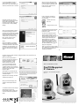
If you need installation program to
create a desktop icon or a quick
launch icon for you, click all items you
need here, and click "Next" to continue.
When a (or more) camera is found,
select it by mouse to highlight it, and
then click "Browse Camera via Web"
button to launch web browser to
connect to IP camera.
If the "IP Address" of camera is
"0.0.0.0", please click "Configure
Camera" button.
Here lists all options you chose in
previous steps, if everything's correct,
click "Install" to start installing
procedure, or click "Back" to go back
to previous step to modify installing
settings.
"Browse Camera via
Web" icon
"Configure Camera" icon
You'll be prompted to input username
and password. Username is "root",
password is "pass".
When you see this window, it means
the software installing procedure is
complete. Please click "Finish" to finish
the procedure (IP camera surveillance
software will start after you click
"Finish' button, if you want to start it
later, uncheck "Launch IP Cam
Surveillance Software" box).
IP Camera is working through the
network (TCP/IP Protocol). The IP
address setting must be correct, or you
cannot access to the camera. The
wizard program will detect the IP
address status of your network
automatically and suggest a free IP
address for the Camera. You can
accept the suggested value or enter
the value manually. Click OK to
apply the configuration.
Step 2
When the installation is completed.
Please run" Micronet IP Scan Utility
".The utility will search for all cameras
available on your local network. You
can click "Search Camera" button to
search for cameras on your network
again.
Search Camera icon
5
Or select "DHCP" to obtain an auto IP setting from DHCP server and click "OK" to
apply the configuration.
Note: If you don't know how to specify
an IP address for your camera, please
ask your network administrator or
experienced technician.
6
Communicate via
Now you can use web browser to
connect to IP camera by inputting IP
camera's IP address in the web
browser's address bar, or click
"Browse camera via Web" icon.
If you can't see this login window,
please go back to Utility and click
"Configure Camera" icon to set the IP
address of the camera before it can be
connected. User name: root
Password: pass
Quick Installation Guide
After logged on, you should see the
following messages appear at the top
of Internet Explorer.
Model No.: SP5532SP/SP5532SW
Pan/Tilt Megapixel
IP Camera
Ver 1.1
Right-click on the message, and click
"Install ActiveX Control "
When you see this message, click
"Install" to install required ActiveX
control
You should be able to see the images
captured by the camera now.
For advanced functions, please refer
to the user manual (on supplied CDROM)
Model No.: SP5532SW
Wireless 802.11n
P/N 2300-0660
WEEE Directive & Product Disposal
At the end its serviceable life ,this product should not be treated
as household or general waste. It should be handed over to the
applicable collection point for the recycling of electrical and
electronic equipment, or returned to the supplier for disposal.
7
Model No.: SP5532SP
PoE 802.3af
w w w . m i c r o n e t . c o m . t w
Introduction
Camera Installation
Thank you for purchasing Micronet SP5532SP/SP5532SW
Pan Tilt IP Camera! This IP camera is an ideal product for all kinds of
video-surveillance purposes, like home/office safety, kid/pet monitoring,
and remote video acquire etc. Unlike conventional close-circuit video
camera, you're not limited to the length of cable! Once this IP camera is
connected to Internet, you can receive video from anywhere in the world
where Internet access is available.
Step 1
Connect the Ethernet cable to your
local area network, and connect the
other end to the LAN jack of this IP
camera.
NOTE: You can skip this step if you
plan to use wireless LAN only.
Package Contents
Prior to the installation of the device, please verify the following
items are in the package:
Step 2
Plug the power adapter to wall
socket, and connect the power
connector to the power jack located
at the bottom of the IP camera.
1 x Internet Camera
1 x Power Adapter
2 x Antenna (SP5532SW only)
1 x Ethernet Cable
1 x Quick Installation Guide
1 x CD (Including Manual/Utility/Driver)
1 x Accessories Pack
If any of the above items are missing, please contact your supplier.
Step 3
Connect the antennas to the
antenna base (located at the back of
the camera)
System Requirement
System requirement for PC, MAC or Notebook PC to access the
Internet Camera are:
Operating System: Windows XP SP2, Vista 32/64 bit, Windows 7
32/64 bit
CPU: 2.0Ghz or above (2.4GHz plus processor with 1GB memory and
a 256MB videocard is required for multiple camera viewing and
recording in IP Surveillance) Intel i3 CPU recommended
Memory Size: 512MB or above 2GB recommended VGA Card
Resolution: 1024 x 768 or above
Internet Explorer 6 or above
Step 4
Place the camera at a secure place,
and point the camera to the place
you wish to monitor. If you wish to
hang the camera on the ceiling or
wall, please use the tripod connector
(located at the bottom of the camera,
as shown on the right) to secure the
camera.
1
2
Camera Overview
Software Installation
LED and Focusing
Follow the simple steps below to run the Install Wizard to guide you quickly
through the Installation process. The following installation is implemented in
Windows XP. The installation procedures in Windows 2000/XP/Server
2003/Vista/Win7 are similar.
The Camera head and its focus ring allow you to modify the aim and
focus of the Camera.
There are two LEDs indicating the camera status and networking status.
Power LED
Audio LED
LAN LED
ACT LED
WLAN LED
Focus Ring
IR LEDs
Microphone
Reset Button
Indicates power status
Indicates Audio status
Indicates LAN activity
Indicates Data activity
Indicates Wireless LAN activity
Adjusts focus
Lights up when environment is too dark
Collects audio
Press the button with pen nib and hold for 5 seconds to
reset the camera settings to factory default value.
Step 1
Insert the CD shipped along with the
Internet Camera into your CD-ROM
drive. First install Micronet IP Scan
Utility. The following installation
steps are the demonstration of
"Micronet IP Scan Utility" and
"MicroView"
9
2
Click "Setup_Micronet_IPScan" and
when the following window appears,
click "Next".
3
IR LED
6
Microphone 7
Reset
8
Power Jack 9
WPS
Antenna Base
Power Connector
SD Card Slot
2
3
4
5
SD Card Slot
Audio-out Connector
Ethernet Port (RJ-45)
Wireless Antenna
4 5 6 7
8
Connects to supplied antenna
Connects to 12V DC power adapter
Accepts SD / SD-HC memory card for image /
video storage
WPS Button
click the buttom on IP Cam and click it on the AP
you want to connect for wireless
Audio Connector
Connects to external speaker for audio output
Ethernet Connector Connect to your local area network
3
You can specify the destination
folder of software installation, you
can just use the default folder, and
click "Next" to continue.
4