1
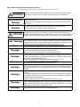
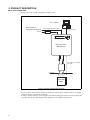
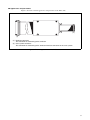
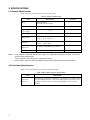
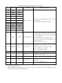
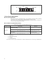
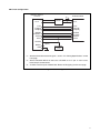
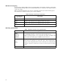
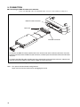
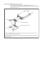
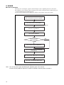
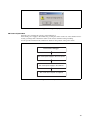
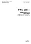
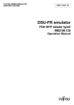
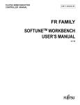
The following document contains information on Cypress products.
FUJITSU MICROELECTRONICS
SUPPORT SYSTEM
SS01-71136-1E
DSU-FR EMULATOR
DSU Cable for Low Voltages
MB2198-20-E
OPERATION MANUAL
PREFACE
Thank you for purchasing the DSU-FR emulator DSU cable for low voltages (MB2198-20-E).
The MB2198-20-E is a development support tool for performing evaluations of application products
that use a FUJITSU FR* family microcontroller (model with tool I/O power supply voltage: 1.8V
specification).
This document is for engineers developing FUJITSU FR family microcontroller application products using the DSU-FR emulator DSU cable for low voltages (referred to as the "DSU cable" in this
document), and describes the functionality and the handling of the DSU cable.
Read this manual thoroughly before using this product.
* : FR, the abbreviation of FUJITSU RISC controller, is a line of products of FUJITSU MICROELECTRONICS LIMITED.
■ Using the product safely
This manual contains important information for using this product safely.
Be sure to read this manual before using the product, and to follow the directions given in this manual
in order to use the product correctly.
In particular, thoroughly read the "■ Caution of the product described in this manual" at the start of
this document, and perform a thorough safety check before using the product.
Store this manual in a safe location where it can easily be accessed at any time while you are using
the product.
■ Warranty and liability disclaimers
The specifications of the product are subject to change without notice.
FUJITSU MICROELECTRONICS assumes no liability for any loss or damage whatsoever directly
or indirectly arising out of the use of the product.
■ Product operating environment
Use the product at an operating temperature of between 5°C and 35°C and at an operating humidity
of between 20% to 80%. Avoid using it in a hot or humid environment and prevent condensation.
You should also keep the packaging materials used for shipping the product. They work well as they
are when you transport the product again, for example, if it becomes out of order and needs to be
repaired.
■ Related manuals
You should refer to the following manuals as well:
• “DSU-FR EMULATOR MB2198-01-E OPERATION MANUAL”
• “SOFTUNE Workbench OPERATION MANUAL”
• “SOFTUNE Workbench USER'S MANUAL”
■ European RoHS compliance
Products with a -E suffix on the part number are European RoHS compliant products.
■ Notice on this document
All information included in this manual is current as of the date it is issued. Such information is subject to change without any prior notice.
Please confirm the latest relevant information with the sales representatives.
i
■ Caution of the product described in this manual
The following precautions apply to the product described in this manual.
WARNING
Indicates a potentially hazardous situation which could result in death or serious
injury and/or a fault in the user's system if the product is not used correctly.
Electric shock,
Damage
Before performing any operation described in this manual, turn off all the power
supplies to the system.
Performing such an operation with the power on may cause an electric shock or
device fault.
Electric shock,
Damage
Once the product has been turned on, do not touch any metal part of it.
Doing so may cause an electric shock or device fault.
CAUTION
Cuts, Damage
Cuts
Damage
Damage
Damage
Damage
Damage
Damage
Damage
Indicates the presence of a hazard that may cause a minor or moderate injury,
damages to this product or devices connected to it, or may cause to loose software
resources and other properties such as data, if the device is not used appropriately.
Before moving the product, be sure to turn off all the power supplies and unplug the
cables. Watch your step when carrying the product. Do not use the product in an
unstable location such as a place exposed to strong vibration or a sloping surface.
Doing so may cause the product to fall, resulting in an injury or fault.
The product contains sharp edges that are left unavoidably exposed.
Handle the product with due care not to get injured with such pointed parts.
Do not place anything on the product or expose the product to physical shocks. Do
not carry the product after the power has been turned on.
Doing so may cause a malfunction due to overloading or shock.
Since the product contains many electronic components, keep it away from direct
sunlight, high temperature, and high humidity to prevent condensation. Do not use
or store the product where it is exposed to much dust or a strong magnetic or electric field for an extended period of time.
Inappropriate operating or storage environments may cause a fault.
Use the product within the ranges given in the specifications.
Operation over the specified ranges may cause a fault.
To prevent electrostatic breakdown, do not let your finger or other object come into
contact with the metal parts of any of the connectors. Before handling the product,
touch a metal object (such as a door knob) to discharge any static electricity from
your body.
When turning the power on or off, follow the relevant procedure as described in this
document.
Before turning the power on, in particular, be sure to finish making all the required
connections. Furthermore, be sure to configure and use the product by following the
instructions given in this document.
Using the product incorrectly or inappropriately may cause a fault.
Always turn the power off before connecting or disconnecting any cables from the
product. When unplugging a cable, unplug the cable by holding the connector part
without pulling on the cable itself. Pulling the cable itself or bending it may expose
or disconnect the cable core, resulting in a fault.
Transporting the product may cause a damage or fault. Therefore, keep the packaging materials and use them when re-shipping the product.
ii
• The contents of this document are subject to change without notice.
Customers are advised to consult with sales representatives before ordering.
• The information, such as descriptions of function and application circuit examples, in this document are presented solely for the purpose of reference to show examples of operations and uses of FUJITSU MICROELECTRONICS semiconductor device; FUJITSU MICROELECTRONICS does not warrant proper operation of the device with respect to
use based on such information. When you develop equipment incorporating the device based on such information, you
must assume any responsibility arising out of such use of the information. FUJITSU MICROELECTRONICS assumes
no liability for any damages whatsoever arising out of the use of the information.
• Any information in this document, including descriptions of function and schematic diagrams, shall not be construed
as license of the use or exercise of any intellectual property right, such as patent right or copyright, or any other right
of FUJITSU MICROELECTRONICS or any third party or does FUJITSU MICROELECTRONICS warrant non-infringement of any third-party's intellectual property right or other right by using such information. FUJITSU MICROELECTRONICS assumes no liability for any infringement of the intellectual property rights or other rights of third
parties which would result from the use of information contained herein.
• The products described in this document are designed, developed and manufactured as contemplated for general use,
including without limitation, ordinary industrial use, general office use, personal use, and household use, but are not
designed, developed and manufactured as contemplated (1) for use accompanying fatal risks or dangers that, unless
extremely high safety is secured, could have a serious effect to the public, and could lead directly to death, personal
injury, severe physical damage or other loss (i.e., nuclear reaction control in nuclear facility, aircraft flight control, air
traffic control, mass transport control, medical life support system, missile launch control in weapon system), or (2)
for use requiring extremely high reliability (i.e., submersible repeater and artificial satellite).
Please note that FUJITSU MICROELECTRONICS will not be liable against you and/or any third party for any claims
or damages arising in connection with above-mentioned uses of the products.
• Any semiconductor devices have an inherent chance of failure. You must protect against injury, damage or loss from
such failures by incorporating safety design measures into your facility and equipment such as redundancy, fire protection, and prevention of over-current levels and other abnormal operating conditions.
• Exportation/release of any products described in this document may require necessary procedures in accordance with
the regulations of the Foreign Exchange and Foreign Trade Control Law of Japan and/or US export control laws.
• The company names and brand names herein are the trademarks or registered trademarks of their respective owners.
Copyright ©2009 FUJITSU MICROELECTRONICS LIMITED All rights reserved
iii
1. OVERVIEW
■ Overview
This product is a development support tool for developing and evaluating hardware and software that
uses a FUJITSU FR family microcontroller (model with tool I/O power supply voltage: 1.8V specification).
This product is used to connect a user system that uses a FUJITSU FR family microcontroller (model
with tool I/O power supply voltage: 1.8V specification) to a DSU-FR emulator (MB2198-01-E)*.
Contact the sales or support representative for details on the applicable microcontrollers.
■ 1.1 Checking the items packaged
Check that the package contains all of the following items before using the product.
• DSU cable
• Operation manual (Japanese version)
• Operation manual (English version, this manual)
:1
:1
:1
■ Optional parts
The optional parts for this product are shown in Table 1.
Table 1 Optional parts
Name
Part number
FUJITSU FR family microcontroller MCU
MB91685 etc.
DSU-FR emulator*
MB2198-01-E
* : Debugging software and communication cables need to be purchased in order to use the emulator. If you are unsure of details, contact the sales or support representative.
1
2. PRODUCT DESCRIPTION
■ System configuration
Figure 1 shows the system configuration of this product.
Host computer
General-purpose
measurement instrument
AC in
External trigger/Program execution
RS232C, USB, LAN
AC
adapter
Fujitsu Emulator
Loader Mode Now.
DSU-FR emulator
[MB2198-01-E]
DSU cable for low voltages
DSU cable
User system
Evaluation
MCU
Figure 1 System configuration diagram
See the operation manual of the emulator for details on connecting the emulator to the host computer
and general-purpose measuring instrument.
In order to use the emulator, a host computer and emulator debugging software need to be purchased
separately. See the operation manual of the emulator for the emulator specifications.
2
■ Appearance and part names
Figure 2 shows the external appearance and part names of the DSU cable.
(2)
(1)
(1) Emulator connector
The connector for connecting to the emulator.
(2) User system connector
The connector for connecting to the emulator interface connector on the user system.
Figure 2 External appearance of the DSU cable
3
3. SPECIFICATIONS
3.1 General Specifications
Table 2 lists the general specifications of the DSU cable.
Table 2 General specifications
Item
Specification
Name
DSU-FR emulator
DSU cable for low voltages
Part number
MB2198-20-E
Operating
power supply
●
●
Provided from the emulator
1.8V
Operating frequency
Max: 66MHz
Temperature
Operation: +5 °C to +35 °C
Storage: 0 °C to + 70 °C
No condensation
Humidity
Operation: 20% to 80%
Storage: 20% to 80%
No condensation
External
dimensions
(W) 62mm × (D) 100mm × (H) 22mm
Weight
Notes:
Remarks
160g
If the product is operated outside of the ranges in the general specifications, there is a risk of the
device becoming damaged.
Use the product within the general specification ranges.
See the data sheets of each of the MCUs you are using for details on the evaluation MCU.
3.2 Functional Specifications
Table 3 shows the functional specifications of the DSU cable.
Table 3 DSU cable functional specifications
Item
DSU cable
functions
4
Specification
This functions as part of the emulator by connecting the user system connector to the emulator interface connector mounted on the user system and connecting the emulator connector to the DSU-FR cable connector on the
emulator.
Table 4 Emulator interface signal line pin assignment
Pin
number
Pin name Input or output
20
ICLK
Input
18
ICS[0]
Input
17
ICS[1]
Input
16
ICS[2]
Input
14
ICD[0]
Input/Output
13
ICD[1]
Input/Output
12
ICD[2]
Input/Output
11
ICD[3]
Input/Output
10
BREAK
Output
5
TRST
Output
8
PLEVEL*1
Output
7
INIT
Output
6
xRSTIN
Input
3
NC
-
2
VCCT*1
Output
1
NC
-
4
UVCC*2
Input
9,15,19
GND
-
Description
Emulator control
Connection conditions
• Connects to the pin with the same name on the evaluation MCU.
• Has a maximum wiring length of 50mm.
• Connects to the reset pin of the evaluation MCU.
• The reset output circuit of the user system and the
evaluation MCU reset pin must be isolated during
use of the emulator.
Evaluation MCU reset
• Activate when an “L” level signal is output.
• Open drain output. Includes a 10kΩ pull-up resistor
using the UVCC pin.
(VOL= +0.4V max, IOL=12mA)
User system reset
-
• Connects to the reset output circuit of the user system.
• Activate when an “L” level signal is input.
(VIH = +1.7V min, IIH = -10µA)
(VIL = +0.8V max, IIL = 10µA)
Must be left unconnected because it is not used.
Dedicated DSU power Connects to the pin with the same name on the evalusupply
ation MCU (+3.3V / 350mA).
-
Must be left unconnected because it is not used.
User system power
supply
Connects to the external I/O power supply of the evaluation MCU.
(0V to +1.8V / 100mA or less)
GND
Connects to the VSS pin (0V) of the evaluation MCU.
*1 : There are some models that do not have a PLEVEL or VCCT pin depending on the evaluation MCU, and this pin
must be left open in this case.
*2 : When the MCU has a single power supply, connect this to the VCC pin, and when the MCU has multiple power supplies, connect this to the tool I/O power supply.
5
Index
▼
1 pin
19 pin
2 pin
20 pin
Figure 3 User system connector pin layout
3.3 User System Specifications
■ User system specifications
This section covers the recommended models, circuit configuration, design precautions, and wiring
specifications for the emulator interface connector mounted on the user system.
When using flat cables, FUJITSU MICROELECTRONICS recommends selecting a combination of
connectors along with appropriate housing.
■ Part numbers of recommended connectors
Table 5 Part numbers of recommended connectors
Attached cable
Flat cable
Part number
Remarks
FAP-2001-120x*-0BS
(manufactured by YAMAICHI ELECTRONICS CO., LTD.)
Includes housing and a short latch
FAP-20-08#x*-0BF
(manufactured by YAMAICHI ELECTRONICS CO., LTD.)
Includes housing but no latch
FAP-20-04#x*
(manufactured by YAMAICHI ELECTRONICS CO., LTD.)
No housing included
(beware of insertion mistakes)
* : The “x” represents each of the following terminal forms:
x = 1: Right angle
x = 2: Right angle/solder dip
x = 3: Straight
x = 4: Straight/solder dip
See the data sheet of the respective manufacturer according to information such as connector type and dimensions.
6
■ Circuit configuration
Emulator interface
connector
VCC
UVCC
2
VCCT *
FUSE *1
*3
Evaluation MCU
VCC
VCCT
ICLK
ICS[2:0]
ICD[3:0]
ICLK
ICS[2:0]
ICD[3:0]
BREAK
PLEVEL*2
TRSTX
INITX
BREAK
PLEVEL
TRSTX
INITX
*3
*3
xRSTIN
DSUIO
(Open)
Reset output
circuit
GND
VSS
*1 : See the information concerning UVCC and VCCT in “Wiring Specifications” on the
next page.
*2 : Some evaluation MCUs do not have a PLEVEL or VCCT pin. In such cases,
leave the pin unconnected.
*3 : A switch circuit may be needed. See “Notes on Designing” on the next page.
Figure 4 Circuit configuration
7
■ Notes on designing
To operate the evaluation MCU on the user system without connecting the emulator, you must adequately terminate the input pins of the evaluation MCU that are connected to the emulator interface
on the user system.
Take care when designing the user system as a switching circuit may be needed for this purpose.
The termination of emulator interface pins is shown in Table 6.
Table 6 Emulator interface pin termination
Evaluation MCU
pin name
Termination
VCCT
Must be connected to the VCC pin (+1.8V power) of the evaluation MCU.
TRST
Must be connected to the reset output pin of the user system.
INIT
Must be connected to the reset output pin of the user system.
Other
Must be left unconnected.
■ Wiring specifications
Table 7 Emulator interface wiring specifications
Signal line name
8
Wiring specification
ICLK
ICS[2:0]
ICD[3:0]
BREAK
• The total wiring length of each signal line (from the evaluation MCU pin
to the Emulator interface connector pin) must be 50mm or less.
• The total wiring lengths of every signal line may differ by 20mm at the
most. The total wiring length of ICLK must be the shortest.
UVCC
VCCT
• Prepare wiring in a pattern with more capacity than the rated current.
• An erroneous connection of a probe may cause a short-circuit between a
power source and ground or be a reverse connection. As a safety measure,
include a protective circuit such as a fuse in each of the power circuit patterns.
GND
Connect directly to power circuit patterns, such as the ground plane.
4. CAUTIONS
■ General cautions on the DSU cable
• Disconnect all of the power supplies from the emulator and user system before connecting the
DSU cable.
• Power is not supplied from the DSU cable or emulator to the user system.
• This product supports FUJITSU FR microcontroller models with 1.8V tool I/O power supply
voltage specifications. If you are using a model with other operating voltage specifications
(tool I/O power supply voltage of 2.5V or more), use the optional DSU-FR emulator DSU cable (MB2198-10-E).
9
5. CONNECTION
■ Connecting the DSU-FR cable to the emulator
Connect the DSU-FR cable to the DSU-FR cable connector on the emulator (see Figure 5).
DSU-FR cable connector
Lock lever
Emulator connector
To connect the DSU-FR cable, hold the lock levers at both ends of the emulator connector, insert the
emulator connector into the DSU-FR cable connector, and then push the emulator connector until it locks
into place.
To remove the DSU-FR cable, hold the lock levers at both ends of the emulator connector, undo the lock,
and then remove the DSU-FR cable from the DSU-FR cable connector.
Figure 5 Connecting the DSU cable to the emulator
Note : Turn power off before board setting/removal.
Apply even force to the connector for unplugging the board.
10
■ Connecting the DSU-FR cable to the user system
The DSU cable connects to the DSU connector on the user system (see Figure 6).
See the "DSU-FR EMULATOR MB2198-01-E OPERATION MANUAL" for details on the recommended part number, circuit configuration, design-time cautions, and wiring specifications of the
emulator interface connector.
Index
User system connector
Emulator interface connector
User system
To connect the DSU-FR cable, connect the emulator interface connector on the user system and the
user system connector by aligning their indexes.
To remove the DSU-FR cable, pull the user system connector out from the emulator interface connector
on the user system.
Figure 6 Connecting the user system
11
6. USAGE
■ Power-on procedure
Turn the power on using the sequence shown in Figure 7 after completing all of the connections.
The emulator power is turned on by pressing the power switch on the back of the emulator. The power switch remains depressed when pressed.
See the operation manual of the emulator for details on the position of the power switch.
Turn on the power to the host computer
Turn on the power to the emulator
The POWER LED lights up.
Run SOFTUNE Workbench
Run emulator debugger
Has the emulator
been initialized?
YES
NO
Carry out the emulator initialization
Check the dialog box that is displayed
(see Figure 8)
Turn on the power supply to the user system
Click “OK” on the displayed dialog box
Figure 7 Power-on procedure
Note : Turn on the power supply by following the sequence given in this manual.
Do not carry the product or expose it to shocks or vibrations after the power is turned on.
12
Figure 8 Dialog box display
■ Power-off procedure
Turn the power off using the sequence shown in Figure 9.
Turn off the power supply to the emulator by pressing the switch on the rear of the emulator and releasing your finger. The switch then returns to the off state with the switch protruding.
See the operation manual of the emulator for details on the position of the power switch.
Exit "Emulator Debugger"
Turn off the power supply to the user system
Turn off the power supply to the emulator
Turn off the host computer as required
Figure 9 Power-off procedure
13
SS01-71136-1E
FUJITSU MICROELECTRONICS • SUPPORT SYSTEM
DSU-FR EMULATOR
DSU Cable for Low Voltages
MB2198-20-E
OPERATION MANUAL
January 2009 the first edition
Published FUJITSU MICROELECTRONICS LIMITED
Edited
Sales Promotion Department