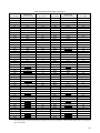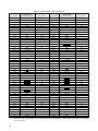
1
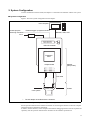
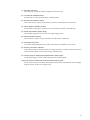
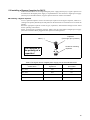
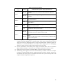
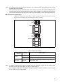
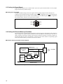
The following document contains information on Cypress products.
FUJITSU MICROELECTRONICS
SUPPORT SYSTEM
SS01-71109-1E
DSU-FR EMULATOR
PGA-401P ADAPTER TYPE 2
MB2198-130-E
OPERATION MANUAL
PREFACE
Thank you for purchasing the DSU-FR emulator PGA-401P adapter type 2 (MB2198-130-E).
The MB2198-130-E is a development support tool for performing evaluations of application products that use a FUJITSU MICROELECTRONICS FR family microcontroller*.
This document is for engineers developing FUJITSU MICROELECTRONICS FR family microcontroller application products using the MB2198-130-E (referred to as the “adapter” in this manual),
and describes the functionality and handling of the adapter and the configuration methods. Read this
manual thoroughly before using the adapter.
* : FR, the abbreviation of FUJITSU RISC controller, is a line of products of FUJITSU MICROELECTRONICS LIMITED.
■ Using the product safely
This document contains important information for using this product safely. Be sure to read this
manual before using the adapter, and to follow the directions given in this manual in order to use the
product correctly.
In particular, thoroughly read the "■ Caution of the product described in this manual" at the start of
this document and section "7. Cautions", and perform a thorough safety check before using the product.
Store this document in a safe location where it can easily be accessed at any time while you are using
the product.
■ Warranty and liability disclaimers
The specifications of the product are subject to change without notice.
FUJITSU MICROELECTRONICS assumes no liability for any loss or damage whatsoever directly
or indirectly arising out of the use of the product.
■ Product operating environment
Use the product at an operating temperature of between +5 °C and +35 °C and at an operating humidity of between 20% to 80%. Avoid using it in a hot or humid environment and prevent condensation.
The product is a frameless PC board unit with all electronic components exposed. Therefore, do not
put anything on the product, do not touch or let an electrically charged material contact a metal part
of it. Once the product has been powered, try to keep those objects away from it which may shortcircuit it or easily catch fire and burn. Use the product as horizontal as possible and avoid operating
it at a place exposed to strong vibration, dust, or explosive gas.
Note that using the product not in the above operating environment may unexpectedly cause personal
injury to the user (or another person if present near the product) or physical damage to properties
around the product.
You should also keep the packaging materials used for shipping the product. They work well as they
are when you transport the product again, for example, if it becomes out of order and needs to be
repaired.
■ Related manuals
You should refer to the following manuals as well:
• Evaluation MCU hardware manual or datasheet
• Header operation manual
• DSU-FR EMULATOR MB2198-01-E OPERATION MANUAL
• SOFTUNE Workbench OPERATION MANUAL
• SOFTUNE Workbench USER’S MANUAL
■ European RoHS compliance
Products with a -E suffix on the part number are European RoHS compliant products.
■ Notice on this document
All information included in this document is current as of the date it is issued. Such information is
subject to change without any prior notice.
Please confirm the latest relevant information with the sales representatives.
i
■ Caution of the product described in this manual
The following precautions apply to the product described in this manual.
WARNING
Indicates a potentially hazardous situation which could result in death or serious
injury and/or a fault in the user’s system if the product is not used correctly.
Electric shock,
Damage
Before performing any operation described in this manual, turn off all the power
supplies to the system.
Performing such an operation with the power on may cause an electric shock or
device fault.
Electric shock,
Damage
Once the product has been turned on, do not touch any metal part of it.
Doing so may cause an electric shock or device fault.
CAUTION
Cuts, Damage
Cuts
Damage
Damage
Damage
Damage
Damage
Damage
Damage
Damage
Indicates the presence of a hazard that may cause a minor or moderate injury, damages to this product or devices connected to it, or may cause to loose software resources and other properties such as data, if the device is not used appropriately.
Before moving the product, be sure to turn off all the power supplies and unplug the
cables. Watch your step when carrying the product. Do not use the product in an
unstable location such as a place exposed to strong vibration or a sloping surface.
Doing so may cause the product to fall, resulting in an injury or fault.
The product contains sharp edges that are left unavoidably exposed, such as jumper plugs.
Handle the product with due care not to get injured with such pointed parts.
Do not place anything on the product or expose the product to physical shocks. Do
not carry the product after the power has been turned on.
Doing so may cause a malfunction due to overloading or shock.
Since the product contains many electronic components, keep it away from direct
sunlight, high temperature, and high humidity to prevent condensation. Do not use
or store the product where it is exposed to much dust or a strong magnetic or electric field for an extended period of time.
Inappropriate operating or storage environments may cause a fault.
Use the product within the ranges given in the specifications.
Operation over the specified ranges may cause a fault.
To prevent electrostatic breakdown, do not let your finger or other object come into
contact with the metal parts of any of the connectors. Before handling the product,
touch a metal object (such as a door knob) to discharge any static electricity from
your body.
When turning the power on or off, follow the relevant procedure as described in this
document.
Before turning the power on, in particular, be sure to finish making all the required
connections. Furthermore, be sure to configure and use the product by following the
instructions given in this document.
Using the product incorrectly or inappropriately may cause a fault.
Always turn the power off before connecting or disconnecting any cables from the
product. When unplugging a cable, unplug the cable by holding the connector part
without pulling on the cable itself. Pulling the cable itself or bending it may expose
or disconnect the cable core, resulting in a fault.
Because the structure of the MCU socket does not allow an evaluation MCU to be
mounted in the incorrect orientation, be very careful of the orientation of the evaluation MCU when mounting it.
Inserting the evaluation MCU in the wrong orientation may damage the MCU, causing the MCU to become faulty.
Because the product has no casing, it is recommended that it be stored in the original packaging. Transporting the product may cause a damage or fault. Therefore,
keep the packaging materials and use them when re-shipping the product.
ii
• The contents of this document are subject to change without notice.
Customers are advised to consult with sales representatives before ordering.
• The information, such as descriptions of function and application circuit examples, in this document are presented solely for the purpose of reference to show examples of operations and uses of FUJITSU MICROELECTRONICS semiconductor device; FUJITSU MICROELECTRONICS does not warrant proper operation of the device with respect to
use based on such information. When you develop equipment incorporating the device based on such information, you
must assume any responsibility arising out of such use of the information. FUJITSU MICROELECTRONICS assumes
no liability for any damages whatsoever arising out of the use of the information.
• Any information in this document, including descriptions of function and schematic diagrams, shall not be construed
as license of the use or exercise of any intellectual property right, such as patent right or copyright, or any other right
of FUJITSU MICROELECTRONICS or any third party or does FUJITSU MICROELECTRONICS warrant non-infringement of any third-party's intellectual property right or other right by using such information. FUJITSU MICROELECTRONICS assumes no liability for any infringement of the intellectual property rights or other rights of third
parties which would result from the use of information contained herein.
• The products described in this document are designed, developed and manufactured as contemplated for general use,
including without limitation, ordinary industrial use, general office use, personal use, and household use, but are not
designed, developed and manufactured as contemplated (1) for use accompanying fatal risks or dangers that, unless
extremely high safety is secured, could have a serious effect to the public, and could lead directly to death, personal
injury, severe physical damage or other loss (i.e., nuclear reaction control in nuclear facility, aircraft flight control, air
traffic control, mass transport control, medical life support system, missile launch control in weapon system), or (2)
for use requiring extremely high reliability (i.e., submersible repeater and artificial satellite).
Please note that FUJITSU MICROELECTRONICS will not be liable against you and/or any third party for any claims
or damages arising in connection with above-mentioned uses of the products.
• Any semiconductor devices have an inherent chance of failure. You must protect against injury, damage or loss from
such failures by incorporating safety design measures into your facility and equipment such as redundancy, fire protection, and prevention of over-current levels and other abnormal operating conditions.
• Exportation/release of any products described in this document may require necessary procedures in accordance with
the regulations of the Foreign Exchange and Foreign Trade Control Law of Japan and/or US export control laws.
• The company names and brand names herein are the trademarks or registered trademarks of their respective owners.
Copyright © 2008 FUJITSU MICROELECTRONICS LIMITED All rights reserved
iii
1. Overview
This product is a development support tool for developing and evaluating hardware and software that
uses the FUJITSU MICROELECTRONICS FR family microcontroller.
■ Overview
It is used with the DSU-FR emulator header*1 to connect the user system corresponding to the
FUJITSU MICROELECTRONICS FR family microcontroller and the DSU-FR emulator (MB219801-E)*2.
*1 : Referred to as the “header” in this document.
*2 : Referred to as the “emulator” in this document.
The main features of this product are as follows.
• The adapter consists of an adapter board and flat cables (2 sets of the Standard and Long
types).
• The adapter board has an on-board IC socket for evaluation MCU (401-pin PGA package
code: PGA-401C-A02).
• Connected to the header using a flat cable (standard or long one)
• Used in combination with the header to connect the emulator and the user system
• Power to the adapter is supplied from the user system via the emulator or header.
• Supports the internal ROM emulation memory function.
• Supports the external memory emulation function.
• Supports the external trace function.
• Supports the power-on debug function.
■ Checking the items packaged
Check that the package contains all of the following items before using the product.
• Adapter board:
1
• Flat cables (Standard: 8cm):
2
• Flat cables (Long: 20cm):
2
• Operation manual (Japanese version):
1
• Operation manual (English version: this document):
Note : Transporting the product may cause a damage or fault. Therefore, keep the packaging materials and
use them when re-shipping the product.
1
■ Optional parts
The optional parts for this product are shown in Table 1. Purchase them as required.
Table 1 Optional parts
Name
Part number
Evaluation MCU
FUJITSU MICROELECTRONICS
FR family microcontroller (MB91Vxxx)*1
DSU-FR emulator
MB2198-01-E*2
DSU-FR emulator header
MB2198-XXX-E*3
DSU-FR emulator memory board*4
−
Oscillator*5, Capacitor*5
−
*1 : The package code of the evaluation MCU is PGA-401C-A02. If you do not know the type and
package code of the evaluation MCU that can be used for this product, contact the sales or support representative.
*2 : Debugger software and communications cables need to be purchased in order to use the emulator.
If you are unsure of the details, contact the sales or support representative.
*3 : The header is an interface board used to connect the user system to the emulator.
Select and purchase the suitable header for the mass production MCU to be used.
See the header operation manual for handling and using headers and precautions of safe use.
*4 : The memory board is required to use the external-memory emulation function (under planning).
*5 : See the data sheet of evaluation MCU for details on the frequency of the oscillator to use.
Furthermore, see the data sheet of the oscillator for details on the values of the capacitors to
connect to the oscillator.
2
2. System Configuration
Used in combination with the header, the adapter is connected to the emulator and the user system.
■ System configuration
Figure 1 shows the system configuration for the adapter.
Host computer
General-purpose
measuring instrument
AC in
External trigger / program execution
RS232C, USB, LAN
AC adapter*
Fujitsu Emulator
Loader Mode Now.
DSU-FR emulator
Evaluation
MCU
Adapter board
Adapter
(this product)
Flat cable
Header board
Header
User system
* : The AC adapter is bundled with the emulator.
Figure 1 System configuration diagram
See the operation manual of the emulator for details on connecting the emulator to the host computer
and general-purpose measuring instrument.
In order to use the emulator, a host computer and emulator debugging software need to be purchased
separately. See the operation manual of the emulator for the emulator specifications.
3
■ Appearance and part names
Figure 2 gives an external view of the adapter board to identify each part of it.
The adapter board illustrated in Figure 2 is in the factory default states.
(1)
(2)
(3)
A
EML
S9 VSEL4
(9)
USR
C
S8 VSEL3
B
−
SW2
EML
S7 VSEL2
USR
SW4
A8
A9
A10
A11
A12
A13
A14
A15
A16
A17
A18
A19
A20
A21
SW3
1 2 3 4 5 6 7 8
−
ON
1 2 3 4 5 6 7 8
ON
S6 VSEL1
USR
+
+
ON
1 2 3 4 5 6 7 8
RD
A1
A2
A3
A4
A5
A6
A7
C7(SC8,9)
ON
1 2 3 4
1
2
3
+
SW1
(8)
EML
S5
SC2
ASEL
−
C6(SC6,7)
+
C2(SC4,5)
EML
S4
−
EML
USR
INIT
TRST
EML
USR
(5)
C11(SC10,11)
M2(SC1)
(4)
SC3
X0A/X1A
X0A
USR
X1A
CN5
X0/X1
(6)
X0
USR
X1
(10)
(7)
Figure 2 External view
4
(1) Emulator connector
This connector accepts the emulator (Mounted on the rear side).
(2) IC socket for evaluation MCU
401-pin PGA IC socket for mounting an evaluation MCU
(3) Memory size selection switch
This switch sets the capacity of the memory board to use external-memory emulation.
(4) DVCC bypass capacitor sockets
These sockets accept bypass capacitors to be inserted between DVCC and GND pins.
(5) Reset signal setting jumper plugs
These jumper plugs are used to set the reset signal supply source.
(6) Memory board connector
This connector accepts a memory board (for external-memory emulation).
(7) Flat cable connectors
Use the flat cable packaged in this product, and connect to the header or user system.
(8) Memory connection switches
If the external memory emulation function is being used, these switches connect the I/O ports
of the evaluation MCU to the external memory emulation lines.
(9) Jumper plugs for setting the evaluation MCU power supply
These jumper plugs are used to make settings for the evaluation MCU.
(10) Clock input IC sockets and clock input select jumper plugs
The IC sockets accept an oscillator and a capacitor for the main clock and sub clock; the jumper
plugs are used to set the clock supply source.
5
3. Specifications
■ General specifications
Table 2 lists the general specifications of the adapter.
Table 2 General specifications
Item
Specification
Name
DSU-FR emulator PGA-401P adapter type 2
Part number
MB2198-130-E
Power supplies
Evaluation MCU: Internal power supply*
0 V to +5.5 V (UVcc)
Evaluation MCU: I/O power supply*
0 V to +5.5 V (UVcc)
Adapter board power supply
+3.3 V
(Supplied from emulator)
Internal operating
frequency of MCU
Max: 34MHz
Temperature
Operation: 5 °C to 35 °C
Storage: 0 °C to 70 °C
Humidity
Operation: 20% to 80% (No condensation)
Storage: 20% to 80% (No condensation)
External dimensions
(W) 205mm × (D) 110mm × (H) 30mm
(Including the IC socket and connector dimensions)
Weight
173g
* : For details on the internal power supply and I/O power supply of each evaluation MCU, see the
power supply specifications of the evaluation MCU. For details on each of the power supplies,
see the "Evaluation MCU hardware manual" or contact the sales or support representative if you
are unsure.
Note : Operating the device outside the range of any general specification may cause the device to malfunction. Use the device in the ranges of its general specifications.
6
■ Function specifications
Table 3 lists the major function specifications of the adapter.
Table 3 Adapter function specifications
Item
Description
Adapter function
Used in combination with the DSU-FR emulator and header, it functions as the adapter
for connecting the emulator to the evaluation MCU and user system.
External trace memory
Supports the external trace function. Trace length of 64K frames.
Internal ROM emulation
Supports the internal ROM emulation memory function. 1Mbyte max.
Supports the external memory emulation*1 function. Can be configured as RAM or
ROM, and the memory capacity is selectable. This function is implemented by mounting
an optional memory board on the adapter board.
The capacity of the memory board can be selected from
Memory capacity select among seven steps between 2M words and 32K words
(1 word = 16 bits).
External memory emulation
Memory connection
Address lines that are disabled by the memory capacity selection function are able to be disconnected from the buffers and
used as user resources instead.
Furthermore, even when the external memory emulation function is not being used, the load associated with using the address lines as user resources can be reduced by disconnecting
the lines.
Power-on debugging
Supports the power-on debug function*2 which runs a program immediately after the
power-on sequence of the evaluation MCU.
Jumper plugs
The jumper plugs on the adapter board can be used to make various settings of the adapter.
Clock input IC sockets
The adapter has IC sockets for using oscillators to supply clock signals from the adapter
to the main clock (X0/X1) and sub clock (X0A/X1A) pins of the evaluation MCU.
*1 : The evaluation MCU must support the external-memory emulation feature. The total amount of memory available
depends on the memory capacity of the memory board, the memory capacity selection switches, and the settings
of the evaluation MCU. Before using this function, see the “Evaluation MCU hardware manual” or contact the sales
or support representative if you are unsure. For details, see Section 6.4 "Setting the External Memory Emulation"
Note also that this function is added to the external bus of the evaluation MCU. Before using the function, read “7.
Cautions” carefully.
*2 : This function assumes that the evaluation MCU supports the power-on debug feature. Before using the function,
see the “Evaluation MCU hardware manual” or contact the sales or support representative if you are unsure.
7
■ Connector and socket specifications
Table 4 lists the specifications of the connectors and IC sockets mounted on the adapter board.
Table 4 Connector and IC socket specifications
Item
Description
Emulator connector
Use this connector to connect the emulator to the adapter.
For connecting the emulator, see Section 4 "Connection
■ Connecting the adapter board to the emulator".
Flat cable connectors
Connect the adapter to the header using flat cables coming with
the adapter.
For connecting the flat cable, see Section 4 "Connection
■ Connecting the adapter board to the header board".
Evaluation MCU mounting IC
socket
Mount the evaluation MCU (PGA-401P package).
For mounting the evaluation MCU, see Section 5.1 "Installing
the Evaluation MCU".
Memory board connector
Mount an optional memory board.
For mounting the memory board, see Section 5.2 "Installing
the Memory Board".
Oscillator IC sockets
Mount an oscillator and a capacitor authorized for the oscillator.
For mounting the oscillator and capacitor, see Section 6.2 "Setting the Clock Supply Circuit".
If the evaluation MCU has an integrated digital power supply
(such as a DVCC power supply), a bypass capacitor can be
DVCC bypass capacitor mounting
mounted on the digital power supply as required.
sockets
For mounting the bypass capacitor, see Section 5.3 "Installing
a Bypass Capacitor for DVCC".
8
4. Connection
■ Connecting the adapter board to the emulator
Connect the adapter board to the adapter board connector on the emulator as shown in Figure 3.
Adapter board
Emulator connector
Index
Adapter board connector
Emulator
• Insert the connector for connecting the emulator to the adapter board securely to
the far end, and align the index (▲) on each connector for prevention of incorrect
insertion.
• Apply even force to the connector for removing the adaptor board from the emulator.
Figure 3 Connecting the adapter board to the emulator
Note : Turn power off before board setting/removal.
Apply even force to the connector for unplugging the board.
9
■ Connecting the adapter board to the header board
Connect the adapter board to the header board using the flat cables that are provided with the adapter,
as shown in Figure 4.
Adapter board
Flat cable
connector A
Flat cable
connector B
Eject lock
Flat cable
Eject lock
Flat cable
connector A
Flat cable
connector B
Header board
• Insert the eject lock units into the flat cable connectors on each of the boards until
locked.
• Disconnect the flat cables by pulling out the eject locks of the flat cables and releasing the locks.
• To connect the adapter board and the user system directly, mount the specified connector on the user system confirming Item 8. “User Interface”.
Figure 4 Connecting the adapter board with the header board
Note : Before plugging or unplugging the cable, turn off the power supply.
When unplugging the cable, remove it while holding the case connector without pulling the cable itself.
10
5. Installation
5.1 Installing the Evaluation MCU
Install the evaluation MCU on the evaluation MCU mounting IC socket on the adapter board as illustrated in Figure 5 to Figure 7. To uninstall the evaluation MCU, follow the instruction illustrated
in Figure 8.
■ Installing the evaluation MCU
Open the lever of the evaluation MCU mounting IC socket (SC1) to from the dotted-line position to
the solid-line position.
Evaluation MCU
Evaluation MCU mounting IC socket
Figure 5 Installing the evaluation MCU
■ Mounting position
Align pin No. 1 of the evaluation MCU with its pin hole in the evaluation MCU mounting IC socket
(SC1) and insert the evaluation MCU horizontally (check by looking from the above angle).
Evaluation MCU
M2(SC1)
No. 1 pin
Evaluation MCU mounting IC socket
Figure 6 Mounting position
11
■ Securing the evaluation MCU
Close the lever of the evaluation MCU mounting IC socket (SC1) from the dotted-line position to the
solid-line position to lock the evaluation MCU.
Evaluation MCU
Evaluation MCU mounting IC socket
Figure 7 Securing the evaluation MCU
■ Removing the evaluation MCU
To removing the evaluation MCU, open the lever of the evaluation MCU mounting IC socket (SC1)
from the dotted-line position to the solid-line position, then remove the evaluation MCU.
Evaluation MCU
Evaluation MCU mounting IC socket
Figure 8 Removing the evaluation MCU
12
5.2 Installing the Memory Board
When using the external memory emulation function, install an optional memory board into the
memory board connector on the adapter board as illustrated in Figure 9 to Figure 11. To uninstall the
memory board, follow the instruction illustrated in Figure 12.
■ Mounting position
Align the notch on the memory board with the key of the memory board connector.
Memory board
Clips
Memory board connector
CN5
Align these parts
Figure 9 Mounting position
■ Inserting the memory board
Insert the memory board into the memory board connector at an angle as shown in Figure 10 (check
by looking from the side).
Memory board
Memory board connector
Figure 10 Inserting the memory board
13
■ Securing the memory board
Put the memory board down from the dotted-line position to the solid-line position and hold the
memory board between the clips on both sides until it clicks into place to lock it.
Memory board
Memory board connector
Figure 11 Securing the memory board
■ Removing the memory board
To remove the memory board, open the clips on both sides of the memory board connector by pushing them outward (as shown in the left-side sketch in Figure 12).
Pull the memory board up from the dotted-line position to the solid-line position to remove it (as
shown in the right-side sketch in Figure 12).
Memory board
Clips
Memory board connector
CN5
Memory board
Memory board
connector
Figure 12 Removing the memory board
14
5.3 Installing a Bypass Capacitor for DVCC
If the evaluation MCU has an integrated digital power supply (DVCC pin), a bypass capacitor can
be mounted on the digital power supply as required.When it does not have a digital power supply
(DVCC pin) in Evaluation MCU, a bypass capacitor does not need to be mounted.
■ Installing a bypass capacitor
To use a polarized capacitor such as an electrolytic capacitor as the bypass capacitor, install it according to the polarity defined by the silk pattern on the PC board. Use meticulous care to check the
polarity.
Select the appropriate capacitor so that its type, capacitance, and withstand voltage are best suited
for the operating environment.
Figure 13 shows how to install the capacitor. Table 5 lists the signal names of digital power supply
pins of the evaluation MCU plugged in each capacitor mounting socket.
Capacitor
(The longer pin is positive)
Index ( − )
16V
10
It is cautious of
the polarity of a
capacitor!
Socket for mounting
capactors
−
+
Figure 13 Mounting the capacitor
Table 5 The signal names of digital power supply pins of the evaluation MCU
Capacitor mounting
socket name
Correspondence
signal line
Evaluation MCU
pin number
SC4, SC5
PF2
127
SC6, SC7
PD3
241
SC8, SC9
P85
36
SC10, SC11
P65
39
15
6. Setting Procedures
6.1 Setting up the Evaluation MCU Power Supply
Figure 14 shows the power supply circuit configuration of evaluation MCU, Figure 15 shows the factory settings of the jumper plugs of evaluation MCU power supply, and Table 6 shows the evaluation MCU power supply specifications according to the settings of each jumper plug from VSEL1
to VSEL4.
■ Power supply circuit configuration of evaluation MCU
Adapter Board
Emulators
connector
User System
(Board)
+3.3V
MCU mounting part
Flat cable
connector
(MCU mounting
part)
VSEL1
Dedicated
power supply
of emulator
Evaluation MCU
Internal
power supply
EML
USER
VSEL2
USER
Capacitor
0.1uF
C
Internal
MCU
power supply
GND
VSEL3
Main clock
power supply
I/O power-supply
A
MCU
I/O
power-supply
B
VSEL4
External memory
emulation part
EML
USER
Figure 14 Evaluation MCU power supply circuit configuration
■ Settings of evaluation MCU power supply setup jumper plugs (VSEL1 to VSEL4)
VSEL1
USR
EML
VSEL2
USR
C
VSEL3
B
A
VSEL4
USR
EML
Figure 15 Settings of evaluation MCU power supply setup jumper plugs (factory settings)
16
Table 6 Jumper plug settings
Jumper plug
name
Setting
Evaluation MCU power supply specifications
USR side
Supplies from the user system the dedicated power supply for
emulator.
EML side
Supplies the dedicated power supply for the emulator*1 from the
emulator.
USR side
Supplies the user system power supply to the internal power supply
of evaluation MCU.
C side
Adds the capacitor (0.1µF) to the internal power supply of the evaluation MCU*2.
A side
Supplies the main clock power supply*3 from the internal power
supply of evaluation MCU.
B side
Supplies the main clock power supply*3 from the I/O power supply
of evaluation MCU (B side fixed).
USR side
Supplies the back-up power supply*4 from the user system (evaluation MCU I/O power supply) using as RAM.
EML side
Supplies from the emulator the back-up power supply*4 , using as
ROM.
Always use this setting when the external memory emulation function is not being used.
VSEL1
VSEL2
VSEL3
VSEL4
*1 : When using a power-on debugging function, it is necessary that the dedicated power supply for
emulator should be supplied from an emulator (EML side), and the evaluation MCU should
support the power-on debugging function. See the "Evaluation MCU hardware manual" or
"datasheet", for information whether the evaluation MCU supports power-on debbugging
function. Contact the sales or support representative if you are unsure.
*2 : For the specifications of the internal power supply of evaluation MCU, see the “Evaluation
MCU hardware manual” or contact the sales or support representative if you are unsure.
*3 : Supply the I/O power supply of evaluation MCU to the main clock power supply.
*4 : The backup power supply is used for the external-memory emulation circuit on the adapter
board.To use the data backup function, supply backup power from the emulator. In this case,
the emulator detects the power-on or shutdown state of the user system to back up data on the
adapter board (ROM equivalent operation).
17
6.2 Setting the Clock Supply Circuit
The clock peripheral circuit configuration to the evaluation MCU are shown in Figure 16, the installing method of oscillator in Figure 17, the factory default setting of clock selection jumper plug in
Figure 18, and the correspondence between clock selection jumper plug and clock supply in Table 7.
■ Clock peripheral circuit configuration
User system
(Board)
Adapter Board
USR
X1
EML
X1
X1
USR
X0
EML
X0
X0
X0/X1
1
2
3
4
Evaluation
MCU
8
7
6
5
GND
GND
USR
X1A
EML
X1A/PF6
X1A
USR
X0A
EML
Flat cable
connector
X0A/PF5
X0A
X0A/X1A
1
2
3
4
8
7
6
5
GND
GND
Figure 16 Clock peripheral circuit configuration of evaluation MCU
■ Installing the oscillator
Mount the oscillators and capacitors on the oscillator IC sockets (SC2, SC3) of the adapter board to
supply the clock signal from the adapter board to the main clock (X0/X1) and to sub clock (X0A/
X1A) of the evaluation MCU respectively.
Oscillator
Install the capacitor across pins 2
and 4 or across pins 3 and 4.
Install the capacitor across pins 5
and 6 or across pins 5 and 7.
Capacitor
Capacitor
• See the data sheet of the evaluation MCU for the oscillator frequency and other details.
• See the oscillator data sheet for details on the capacitor's capacitance.
• The oscillator and capacitors are not provided with this product and need to be purchased separately.
Figure 17 Installing the oscillator
18
Note : For a cpacitor that is mounted with the oscillator, use a capacitor about 10pF smaller than the recommended value of the oscillator.
When a capacitor of the recommended value of the oscillator is mounted, an oscillator stabilization time
becomes longer than the standard time due to the parasitic capacitance of a socket and the influence
of an interconnect load and that may cause a failure such as instability of clock switching operation etc.
■ Clock selection jumper plugs
The factory settings of the jumper plugs are shown in Figure 18, and the correspondence between
the clock selection jumper plugs and clock supply is shown in Table 7.
X0
USR
X1
EML
X0/X1
X0A
USR
X1A
EML
X0A/X1A
Figure 18 Setting the clock selection jumper plugs (factory setting)
Table 7 Jumper plug settings
Jumper plug
name
Setting
Clock supply*
USR side
Supply main clock signal from user system.
EML side
Supply main clock signal from oscillator IC socket on adapter.
EML side
Supply sub clock signal from oscillator IC socket on adapter
(fixed on EML side).
X0,X1
X0A,X1A
* : There is no function to supply a clock signal from the adapter to the user system.
Note : To supply the main clock from the user system, create the oscillation circuit on the user system, buffer
the main clock via the CMOS buffer or the like, and then supply it.
Since supplying the sub clock from the user system may result in instable operation, be sure to supply
the sub clock from the adapter board.
19
6.3 Setting the Reset Signal
Supply the reset signals to the evaluation MCU by the user system and the emulator. Use the jumper
plugs with the factory default settings.
■ Setting the reset signal
The factory default settings of the reset signal selection jumper plugs are shown in Figure 19.
Under the factory default settings, the INITX signal (INIT) is supplied to the evaluation MCU from
the INITX signal on the user system via the emulator, and the TRSTX signal (TRST) is supplied to
the evaluation MCU from the reset signal of the emulator.
INIT
USR
EML
USR
EML
TRST
Figure 19 Setting the reset signal setting jumper plugs (factory setting)
6.4 Setting the External Memory Emulation
The external memory emulation block diagram is shown in Figure 20, the settings of the switch are
shown in Figure 21 and the memory board sizes and valid addresses selected by the switches are
shown in Table 8, the factory settings of the memory connection switches are shown in Figure 22,
and the individual switches in each memory connection switch block and the corresponding signal
lines and evaluation MCU pin numbers are shown in Table 9.
■ External memory emulation block diagram
Data bus
Evaluation
MCU
P1[7:0],P0[7:0]
Memory
connection
74LVCH16244A
switch
Externalmemory emulation circuit
Y
Flat cable
connector
Address bus
P4[5:0],P3[7:0],P2[7:1],P5[4]
A
*OE
GND
Adapter board
Figure 20 External memory emulation block diagram
20
To header
■ Setting the memory size selection switch
The memory size selection switch select the size of the memory board to be connected when the external memory emulation function is being used.
ASEL
ON
1 2 3 4
1
2
3
SW1
Figure 21 Setting the memory size selection switch (factory default settings)
Table 8 The memory size selection switch settings
ASEL3
ASEL2
ASEL1
Memory board size
Valid addresses
1
1
1
1
1
0
2 MWords
A[21:1]
1
0
1
1 MWords
A[20:1]
1
0
0
512 KWords
A[19:1]
0
1
1
256 KWords
A[18:1]
0
1
0
128 KWords
A[17:1]
0
0
1
64 KWords
A[16:1]
0
0
0
32 KWords
A[15:1]
■ Setting the memory connection switches
When the external memory emulation function is used, the address lines that are disabled by the
memory size selection setting can be disconnected from the buffers and used as user resources instead. Even when the external-memory emulation function is not used, the switches can be used to
disconnect those address lines from buffers to reduce the load on the address lines used as user resources.
The factory default settings of the switches are shown in Figure 22 and the individual switches in
each switch block and the corresponding signal lines and evaluation MCU pin numbers are shown
in Table 9.
SW2
RD
A1
A2
A3
A4
A5
A6
A7
1 2 3 4 5 6 7 8
ON
A8
A9
A10
A11
A12
A13
A14
A15
1 2 3 4 5 6 7 8
ON
SW3
A16
A17
A18
A19
A20
A21
1 2 3 4 5 6 7 8
ON
SW4
Figure 22 Setting the memory connection switches (factory default settings)
21
Table 9 The memory connection switch settings
Part number
(Printed on board)
SW2
SW3
SW4
Element number
(Labeled on switch)
1
2
3
4
5
6
7
8
1
2
3
4
5
6
7
8
1
2
3
4
5
6
Corresponding
signal line*
P54 (RDX)
P21 (A1)
P22 (A2)
P23 (A3)
P24 (A4)
P25 (A5)
P26 (A6)
P27 (A7)
P30 (A8)
P31 (A9)
P32 (A10)
P33 (A11)
P34 (A12)
P35 (A13)
P36 (A14)
P37 (A15)
P40 (A16)
P41 (A17)
P42 (A18)
P43 (A19)
P44 (A20)
P45 (A21)
Evaluation MCU’s
pin number*
140
310
201
357
257
144
309
256
200
356
308
92
44
255
143
199
307
91
142
254
43
198
* : The user resources corresponding to the above pin numbers are different depending on the evaluation MCU used.
For details, see the hardware manual for the evaluation MCU to be used or “8. User Interface”.
22
6.5 Power-on/Shutdown Procedures
Turn the power on after completing all of the connections in the sequence: host computer → emulator
→ user system.
Turn the power off in the sequence: user system → emulator → host computer.
■ Power-on procedure
Turn the power on using the sequence shown in Figure 23 after completing all of the connections.
The emulator power is turned on by pressing the power switch on the rear of the emulator. The power
switch remains depressed when pressed.
See the operation manual of the emulator for details on the position of the power switch.
Turn on the power to the host computer
Turn on the power to the emulator
POWER LED lights up
Run "SOFTUNE Workbench"
Run "Emulator Debugger"
Check that the dialog box (see Figure 24)
Turn on the power supply to the user system
Click "OK" on the dialog box (see Figure 24)
Figure 23 Power-on procedure
Figure 24 Dialog box
23
■ Power-off procedure
Turn the power off using the sequence shown in Figure 25.
Turn off the power supply to the emulator by pressing the switch on the rear of the emulator and releasing your finger. The switch then returns to the off state with the switch protruding.
See the operation manual of the emulator for details on the position of the power switch.
Exit "Emulator Debugger"
Turn off the power supply to the user system
Turn off the power supply to the emulator
Turn off the host computer (as required)
Figure 25 Shutdown procedure
24
7. Cautions
■ General cautions on the adapter
• Disconnect all of the power supplies from the adapter, emulator, and user system before setting any jumper plugs or switches on the adapter board.
• The settings of jumper plugs VSEL1 to VSEL4 are related to the power supply. Setting these
jumper plugs incorrectly may destroy the entire system.
• When a clock signal is supplied ti the evaluation MCU from the user system, the wiring pattern
from the clock signal source on the user system side may be too long to provide oscillation.
• If it is instructed that the X0 or X1 pin should be opened as restricted to the evaluation MCU
when a clock signal is being supplied from the user system to the evaluation MCU using an
oscillator, remove the jumper plug for switching the clock signal supply source on the specified side. This is also applicable to X0A/X1A pin.
• When using the emulator, set the reset signal jumper plug which selects the control source of
the INITX pin of the evaluation MCU to the EML side. When the emulator is being used, the
emulator controls the INITX pin of the evaluation MCU, and the reset input from the user system is not connected directly to the evaluation MCU, but is routed via the emulator. The reset
timing is therefore delayed by several clock cycles compared to the actual reset timing.
Furthermore, when a reset is performed using the emulator reset command, only the evaluation MCU is reset, and the user system is not reset.
In addition, the signal to the INITX pin from the user system is masked by the emulator during
a break.
• The states of the user bus pins when the evaluation MCU is in user hold or low power consumption modes are the same as the states shown in the MCU hardware manual.
• The “flat cable (long)” can be used if the MCU’s clock frequency is low or the load of the user
pin is very low. Basically, use the “flat cable (standard)”.
• If using the adapter and the header, always make sure that the MCU on the user system is socket-mounted to be removed, Use the specified IC socket for the MCU socket.
• Power is not supplied from the adapter, header, or emulator to the user system.
• When the external memory emulation function is not used, set all the memory connection
switches to OFF. If external signals are applied with the memory connection switches set to
ON, drive the adapter at a current of at least ±750µA. If the drive current is lower than
±750µA, a normal potential may not be obtained due to the bus hold feature of the buffer IC.
25
■ Cautions when using the external memory emulation function
• When using the external memory emulation function, set the memory connection switches to
ON that correspond to the valid address bus signals (equivalent to A[21:1] depending on the
memory size settings) and the control lines (equivalent to RDX).
• A buffer IC is connected to the valid address bus signals (which vary depending on the memory size setting) and control lines used for external memory emulation. A capacitance of about
6pF is therefore added to each of the signal conductors.
• As a buffer IC is connected to the valid address bus signals and control lines used for external
memory emulation, each signal conductor connected to the memory board involves a delay
of about 6ns.
• As the data bus used for external memory emulation is connected directly to the data bus signal (equivalent to D[31:16]), the external I/O power supply to the evaluation MCU must always be within +3.3V. If the external I/O power supply exceeds +3.3V, the memory board
may be damaged.
• As the data bus used for external-memory emulation is connected directly to the data bus of
the evaluation MCU, a capacitance of about 6pF is added to each signal conductor when the
memory board is installed.
• The data bus used for external-memory emulation is fixed at 16 bits in width.
• Although some of the address bus signals, data bus signals, and control lines of the memory
board are connected to the user system, the chip select signal is not connected and thus the
user system cannot access data in the memory board.
■ Cautions when using the power-on debug function
• When performing power-on debugging, pay due attention to the settings related to power supply.
• The following three conditions must be satisfied when the power supply is turned off by power-on debugging:
1. It takes 25µs or more for all the power supply levels of the evaluation MCU to decrease from 0.9Vcc to 0.5Vcc.
2. The CPU operating frequency is 1MHz or higher.
3. A user program is being executed.
• For details on the power-on debug function, see the emulator operation manual.
■ Cautions when using the external memory emulation function and the power-on debug function
If the user power supply is shut off with the external address and RDX pins remaining high level, the
bus hold feature of the buffer ICs on the adapter board causes a current of up to 250µA to flow until
each signal level goes low.
26
8. User Interface
■ User Interface Specifications
The correspondence between the pin numbers of flat cable connectors A and B on the adapter board
and those on the header or user system are shown in Figure 26, and the correspondence between the
pin numbers of flat cable connectors A and B and the evaluation MCU is shown in Table 10 and Table 11.
Note that the evaluation MCU signal names in the table are provisional names and the actual signal
names vary with each model. The actual evaluation MCU signal names can be judged from the evaluation MCU pin numbers. If you are unsure of the details, contact the sales or support representative.
The following notation and warnings apply to each of the evaluation MCU signal names.
•
•
•
•
Vcc_A
Vcc_B
VCCXTL
GND
: Internal power supply of the evaluation MCU (or the C pin).
: I/O power supply of the evaluation MCU (or a single power supply).
: Main clock power supply of the evaluation MCU.
: Ground of the evaluation MCU.
Note : The pins that are identified by the underlined evaluation MCU signal names in the table may have additional circuitry attached for controlling the evaluation MCU. As a result, the electrical characteristics
of these pins may differ from an actual MCU.
See the sections listed below for details on the additional circuit for each signal.
• P65/P85/PD3/PF2 (DVcc) : See Section 5.3 "Installing a Bypass Capacitor for DVCC"
• X0/X1
: See Section 6.2 "Setting the Clock Supply Circuit"
• X0A/X1A (PF5/PF6)
: See Section 6.2 "Setting the Clock Supply Circuit"
• P54 (RDX)
: See Section 6.4 "Setting the External Memory Emulation"
P4[5:0] (A[21:16])
P3[7:0] (A[15:8])
P2[7:1] (A[7:1])
P1[7:0] (D[15:8])
P0[7:0] (D[7:0])
The emulator uses Vcc_A and Vcc_B mainly as the power supplies to the evaluation MCU and additionally for voltage detection purposes only; it does not contain circuit consuming large power.
It is recommended to use the “flat cable (standard)” bundled with the emulator to prevent noise trouble.
Provide the user system with a connector equivalent to the flat cable connector. The part number of the
flat cable connector is as follows:
• Flat cable connector part number: 8930E-100-178MS-F (manufactured by KEL)
Note that the pinouts of flat cable connectors A and B are different between the adapter board and the
user system.
27
Adapter board
Header or user system
Flat cable connector
Flat cable connector
CN2
CN1
A
B
A
A50
B50
A50
B50
A1
B1
A1
B1
TOP VIEW
(these connectors are mounted
on the back surface)
B50
B1
B
A50
A1
B1
A50
A1
TOP VIEW
(these connectors are mounted
on the front surface)
Figure 26 Pin numbers of flat cable connectors A and B
28
B50
Table 10 Pinouts of flat cable connector A
Connector
pin number
Evaluation MCU
signal name
(provisional name)*
Evaluation MCU
pin number
Connector
pin number
Evaluation MCU
signal name
(provisional name)*
Evaluation MCU
pin number
A1
A2
A3
A4
A5
A6
A7
A8
A9
A10
A11
A12
A13
A14
A15
A16
A17
A18
A19
A20
A21
A22
A23
A24
A25
A26
A27
A28
A29
A30
A31
A32
A33
A34
A35
A36
A37
A38
A39
A40
A41
A42
A43
A44
A45
A46
A47
A48
A49
A50
GND
P91
P93
P95
P97
AVRH
AVSS
PC1
PC3
PC5
PC7
PA0
Vcc_A
P87
GND
P84
P82
P80
P77
P75
P73
P71
GND
VCC3B
X0A/PF5
P66
P65 (DVcc)
P63
P61
P57
GND
P54 (RDX)
P52
P51
P50
P46
VCCXTL
P21 (A1)
GND
P24 (A4)
P26 (A6)
P30 (A8)
P32 (A10)
P33 (A11)
P35 (A13)
P37 (A15)
P41 (A17)
P43 (A19)
P45 (A21)
GND
−
135
301
191
349
296
186
188
244
187
243
83
−
249
−
302
136
37
138
250
195
38
−
5
209
252
39
40
139
41
−
140
42
306
197
141
76
310
−
257
309
200
308
92
255
199
91
254
198
−
B1
B2
B3
B4
B5
B6
B7
B8
B9
B10
B11
B12
B13
B14
B15
B16
B17
B18
B19
B20
B21
B22
B23
B24
B25
B26
B27
B28
B29
B30
B31
B32
B33
B34
B35
B36
B37
B38
B39
B40
B41
B42
B43
B44
B45
B46
B47
B48
B49
B50
GND
P92
P94
P96
AVCC
AVRL
PC0
PC2
PC4
PC6
GND
PA1
PA2
P90
P86
P85 (DVcc)
P83
P81
GND
P76
P74
P72
Vcc_A
P70
X1A/PF6
P67
GND
P64
P62
P60
P56
P55
P53
Vcc_A
GND
P47
P20
P22 (A2)
P23 (A3)
P25 (A5)
P27 (A7)
P31 (A9)
GND
P34 (A12)
P36 (A14)
P40 (A16)
Vcc_A
P42 (A18)
P44 (A20)
GND
−
84
192
35
131
242
245
297
346
345
−
300
248
193
85
36
303
86
−
351
137
194
−
87
51
251
−
304
88
305
89
196
253
−
−
90
202
201
357
144
256
356
−
44
143
307
−
142
43
−
* : Note that the MCU signal names listed in the table are provisional names, and the actual signal names vary depending on the model.
29
Table 11 Pinouts of flat cable connector B
Connector
pin number
Evaluation MCU
signal name
(provisional name)*
Evaluation MCU
pin number
Connector
pin number
Evaluation MCU
signal name
(provisional name)*
Evaluation MCU
pin number
A1
A2
A3
A4
A5
A6
A7
A8
A9
A10
A11
A12
A13
A14
A15
A16
A17
A18
A19
A20
A21
A22
A23
A24
A25
A26
A27
A28
A29
A30
A31
A32
A33
A34
A35
A36
A37
A38
A39
A40
A41
A42
A43
A44
A45
A46
A47
A48
A49
A50
GND
−
PG4
PG2
PG0
PF2 (DVcc)
GND
PE7
PE5
PE3
PE1
PE0
PD6
PD4
GND
PD2
Vcc_B
PB7
PB5
PB4
PB2
PB0
GND
PA6
PA4
Vcc_B
X1
P17 (D15)
P15 (D13)
P13 (D11)
GND
P10 (D8)
P06 (D6)
P04 (D4)
P02 (D2)
Vcc_B
P00 (D0)
MOD0
GND
PI7
PI5
PI3
PI1
PI0
PH6
PH4
GND
PH1
PH0
GND
−
−
4
208
153
127
−
293
78
184
240
129
294
130
−
80
−
298
189
246
299
81
−
190
134
−
291
258
203
93
−
312
94
205
1
−
46
292
−
206
47
2
150
262
96
207
−
263
264
−
B1
B2
B3
B4
B5
B6
B7
B8
B9
B10
B11
B12
B13
B14
B15
B16
B17
B18
B19
B20
B21
B22
B23
B24
B25
B26
B27
B28
B29
B30
B31
B32
B33
B34
B35
B36
B37
B38
B39
B40
B41
B42
B43
B44
B45
B46
B47
B48
B49
B50
GND
PG5
PG3
PG1
PF3
PF1
PF0
PE6
PE4
PE2
GND
PD7
PD5
PD3 (DVcc)
PG6
PD1
PD0
PB6
GND
PB3
PB1
VCC3IO
PA7
PA5
PA3
X0
GND
P16 (D14)
P14 (D12)
P12 (D10)
P11 (D9)
P07 (D7)
P05 (D5)
P03 (D3)
GND
P01 (D1)
INITX
MOD1
MOD2
PI6
PI4
PI2
GND
PH7
PH5
PH3
PH2
Vcc_B
−
GND
−
50
315
98
182
239
31
183
128
32
−
79
185
241
97
295
344
132
−
348
133
33
247
34
82
29
−
146
259
147
204
260
45
148
−
95
126
30
77
261
313
149
−
48
151
49
3
−
−
−
* : Note that the MCU signal names listed in the table are provisional names, and the actual signal names vary depending on the model.
30
SS01-71109-1E
FUJITSU MICROELECTRONICS • SUPPORT SYSYEM
DSU-FR EMULATOR
PGA-401P ADAPTER TYPE 2
MB2198-130-E
OPERATION MANUAL
August 2008 the first edition
Published FUJITSU MICROELECTRONICS LIMITED
Edited
Business & Media Promotion Dept.