1
Design and Development of a Graphical
Setup Software for the CMS Global
Trigger
Project Report
Philipp Glaser
Tobias Nobauer
Project Supervisor: C.-E. Wulz
Institute for High Energy Physics of the Austrian Academy of
Sciences, Vienna
April 15, 2005
Abstract
A graphical setup program called GTgui has been developed for the Level-1
Global Trigger of the CMS experiment, within a project work for the Vienna
Institute of High Energy Physics. This document describes design and implementation of the program and provides information for future expansion of the
code. A user's manual can be found in the appendix.
The project homepage at
may be consulted for downloads, examples and developer documentation.
http://wwwhephy.oeaw.ac.at/p3w/cms/trigger/globalTrigger/software/setup software.html
2
Contents
1
1.1 From the LHC to GTgui . . . . . . . . . . . . . . . . . . . . . . . 4
1.2 People involved . . . . . . . . . . . . . . . . . . . . . . . . . . . . 4
Introduction
4
2
2.1 Initial Position . . . . . . . . . . . . . . . . . . . . . . . . . . . . 5
2.2 Design Goals . . . . . . . . . . . . . . . . . . . . . . . . . . . . . 5
Pro ject Tasks and Aims
5
3
3.1
3.2
3.3
3.4
3.5
3.6
GTgui Program Structure
6
Overview . . . . . . . . . . . . . . . . . . . . . . . . . . . . . . .
Data Model and Data Context . . . . . . . . . . . . . . . . . . .
Graphical User Interface . . . . . . . . . . . . . . . . . . . . . . .
"Prototype" and "Final" Modes . . . . . . . . . . . . . . . . . .
Input and Output . . . . . . . . . . . . . . . . . . . . . . . . . .
Boolean Expression Parser . . . . . . . . . . . . . . . . . . . . . .
6
7
11
15
18
20
A User's Manual
A.1 Startup Window . . . . . . . . . . . . . . . . . . . . . . . . . . .
A.1.1 Menubar . . . . . . . . . . . . . . . . . . . . . . . . . . .
A.1.2 Toolbar . . . . . . . . . . . . . . . . . . . . . . . . . . . .
A.2 Algorithm Window . . . . . . . . . . . . . . . . . . . . . . . . . .
A.2.1 Algorithm Tree . . . . . . . . . . . . . . . . . . . . . . . .
A.2.2 Algorithm Panel . . . . . . . . . . . . . . . . . . . . . . .
A.3 Prealgo Window . . . . . . . . . . . . . . . . . . . . . . . . . . .
A.3.1 Prealgo Tree . . . . . . . . . . . . . . . . . . . . . . . . .
A.3.2 Prealgo Detailview . . . . . . . . . . . . . . . . . . . . . .
21
B
Scale Files XML Syntax
26
C
Related Web Pages
27
3
21
21
22
22
22
23
23
23
25
1
Introduction
1.1 From the LHC to GTgui
The Large Hadron Collider (LHC), presently under construction at CERN, the
European Organization for Nuclear Research in Geneva, will be the most powerful particle accelerator ever built. Several experiments are being installed at
the collider. One of the two multi-purpose experiments will be the Compact
Muon Solenoid (CMS). Its purpose is to answer many of the open questions in
today's physics. It will be the second largest detector, which will collect huge
amounts of data in the years to come. In order to select only collisions that are
interesting for new physics, a system called trigger has been designed. In CMS
there are two basic trigger levels. The rst level, the Level-1 (L1) Trigger, is
implemented as a specialized, custom-designed electronics system, which makes
use of the latest technology in fast and programmable integrated electronics [1].
It will be housed in part on the individual subdetectors of CMS and in part
in a cavern located next to the actual experiment. The High Level Trigger is
the following and nal step, performed exclusively by o-the-shelf processors.
Regional subtriggers collect data from various detector parts and calculate parameters such as momenta, energies and location information in real time, i.e.
at the LHC collision rate of about 40 MHz. These parameters are passed on to
the Global Trigger [2, 3], which takes the nal decision on whether to reject an
event or to make it available to the HLT for further, more detailed, analysis.
The Global Trigger is a exible system, constructed in FPGA (Field Programmable Gate Array) technology. Up to 192 algorithms (according to the current
state of design) can be loaded into the Global Trigger FPGA chips. These algorithms may be simple or more complex boolean combinations of conditions,
with thresholds and other limits applied. An example for a simple algorithm
would be the requirement of one electron with its transverse energy above a
threshold. A more complex algorithm using topological information might for
example require two electrons with given transverse energies and angular relations (e.g. back-to-back) in order to be fullled. It is the purpose of the GTgui
program described in this document to provide an easy way to set up those
algorithms and conditions and change their parameters such as the thresholds.
1.2 People involved
Apart from the authors of this report, the following people were involved in this
project:
Project Supervisor: Claudia-Elisabeth Wulz
Support and advice: Hannes Sakulin, Anton Taurok, Herbert Rohringer,
Ildefons Magrans de Abril, Manfred Jeitler
All belong to the Institute for High Energy Physics of the Austrian Academy of
Sciences, Vienna, but are partly based at CERN in Geneva. The authors would
like to thank all of them for their kind support!
4
2
Project Tasks and Aims
2.1 Initial Position
As the Global Trigger is fully programmable, a method has to be found to
dene the setup of its logic. The widely used language standard VHDL [4] has
been chosen for programming the hardware. At the beginning of this project, a
program (\GTS") already had been developed that converts a text-based, welldened XML [5] le structure into VHDL code to be compiled and loaded into
the Global Trigger Logic (GTL) electronics chips (see [8]). However, typing a
large XML le by hand is tedious and error-prone; therefore a primitive GUI had
been written at the Vienna Institute to simplify the input. Since that rst GUI
cannot be considered state-of-the-art anymore and lacked necessary features,
this project to develop a new program was launched, which the authors of this
report named \GTgui" - Global T rigger graphical user interface.
The following items sum up the material that was available as a starting
position for this project:
GTS program [8]
CVI Setup Program (old version)
LHCC CMS Technical Design Reports for Trigger and Data Acquisition
[1]
various published and unpublished CMS Notes and Internal Notes
various internal hardware documentation papers developed at the Vienna
Institute
2.2 Design Goals
The following design goals were imposed onto this project by its supervisors:
platform independence
easy extensibility for future requirements (especially concerning I/O)
self-explaining, modern intuitive user interface
compatible with both the prototype (GTL-6U) and the nal (GTL-9U)
versions of the Global Trigger Logic printed circuit boards
extensive consistency checks of user input at input time
5
3
GTgui Program Structure
3.1 Overview
The GTgui program is based on a model view controller architecture, which
separates data storage (model) from the presentation of that data to the user
and provides controls for data manipulation (view). The requirement of platform independence lead to the choice of the Java programming language [6]. To
ensure data integrity and check for various logical requirements at input time,
all data objects are embedded into a \context" class (controller) which has access to all the data objects contained in one trigger setup entity (an XML le).
Simple parameter changes that don't relate to any other part of the setup (such
as a threshold value) aect the data objects only, while more complex changes
(e.g. to the name of a condition, which has to be unique and thus has to be
checked against all the other conditions) are passed on to the context class by
the data objects for validation. For a detailed description of the data model
and context classes, see section 3.2; for the view classes, see 3.3.
Since the program has to be able to deal with both the 6U-sized prototype
and the nal 9U-sized GTL card, which dier in hardware layout and parameters (e.g. the number of output pins, the number and type of chips), an
AbstractF actory design pattern was implemented to ensure consistent use of
classes that are specic to one of these operating modes throughout the program. Furthermore, this pattern hides the details of those classes from the rest
of the program, which thus becomes independent from the operating mode. For
a detailed description, see 3.4.
The purpose of the GTgui program is to generate and manipulate a welldened XML le that contains all the trigger setup data. However, at design
time no nal decision had been taken on whether or not the setup data would
have to be stored in a dierent way (such as a relational database) in the future.
Therefore the XML-specic input/output classes have been hidden from the rest
of the program using abstract interfaces, which makes them easily exchangeable.
The detailed format of the output XML le diers for the prototype and the
nal version operating mode, so the I/O classes are also part of the Abstract
Factory pattern mentioned above. A description of the I/O part of the program
is given in section 3.5.
Trigger prealgorithms and algorithms are boolean expressions that combine
conditions and prealgorithms respectively using boolean operators AND, OR
and NOT. To minimize user errors when entering these expressions, a custom
boolean expression parser was written that checks for syntactical errors at expression input time. This parser is briey described in section 3.6. Conditions,
prealgorithms and alogrithms are explained in more detail in the following section.
6
3.2 Data Model and Data Context
The Global Trigger receives trigger objects from the Regional Triggers. These
objects are candidate electrons or photons (gammas), muons, jets, hadronic decays called \ jets" as well as total and missing transverse energies and jet
multiplicities. Objects representing particles are characterized by their location,
their transverse momentum or energy and quality. Conditions are requirements
applied to a single trigger object or a group of objects. Trigger algorithms
are boolean expressions that combine conditions. On the GTL-6U prototype
also prealgorithms are calculated. These are simple trigger algorithms, which
may not yet be a complete algorithm. Distinct FPGA chips handle conditions
and prealgorithms on one hand, and algorithms on the other. The condition
chips prepare the conditions and the prealgorithms, the simpler algorithm chips
the algorithms. The GTL-9U nal version Global Trigger Logic will only have
condition chips, which will handle conditions and algorithms at the same time.
Prealgorithms will no longer be necessary.
The logical entities conditions, prealgorithms (`prealgos') and algorithms
(`algos') are reected in both the structure of the setup XML le (as designed
by A. Nentschev) and the data model classes implemented in the GTgui program: for example, one instance of the Algo class corresponds to one algorithm
and to one entry in the <algos> section of the XML le. The algorithm logic
on the GTL board yields an output bit that is routed to one of the GTL output
pins. The Algo class therefore contains elds to store the boolean expression,
the chip number and output pin number and methods to get and set those
parameters - quite the same is true for prealgorithms (class Prealgo), which
are a boolean composition of conditions. These two classes are subclasses of
TriggerBooleanCompositionObject to minimize programming eort by sharing common methods.
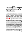
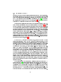
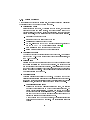
The situation gets a bit more complicated with the trigger conditions, since
several types of conditions exist that take dierent types and numbers of parameters and need dierent input data to be computeable. Altogether, there are
currently 40 such condition types, but some of them dier only slightly (e.g.
in the value of a string input channel specier: \eg" vs. \ieg" for non-isolated
electrons/gammas or isolated electrons/gammas). Therefore the number of distinct classes necessary to implement these condition types could be reduced to
seven, some of which are subclasses of others to benet from intersecting sets of
parameters. The class diagram in Fig. 1 illustrates the resulting class hierarchy.
Condition is an abstract base class for all condition classes, providing common parameters and methods (such as condition chip number, location on the
chip, `condition', `particle' and `type' attributes and their get/set methods).
Class CaloSimpleCondition for example is suitable for all simple (i.e. without
spatial correlation, see below) conditions that require inputs from the Global
Calorimeter Trigger (GCT) and ET threshold, and parameters. This set
of three parameters can be necessary 1{4 times, to describe 1{4 particle con7
Condition
-name : String = new String()
-condition : String = new String()
-particle : String = new String()
-type : String = new String()
-location : String = new String()
-chipnumber : int
...
<<getter>>+getName() : String
<<getter>>+getChipNumber() : int
<<setter>>+setName( val : String ) : void
<<setter>>+setChipNumber( chipnr : int ) : void
...
CaloSimpleCondition
-numberofparticles : int
-et_threshold : int[]
-et_thresholdMin : int
-eta : BigInteger[]
-etaMin : BigInteger
-phi : BigInteger[]
-phiMin : BigInteger
EsumsEttHttCondition
-eThreshold : int
-eThresholdMin : int = 0
-eThresholdMax : int = 0xfff
-enableOverflow : boolean
...
...
...
...
...
<<setter>>+setNumberOfParticles( val : int ) : void
<<getter>>+getNumberOfParticles() : int
<<getter>>+getEtThreshold( number : int ) : int
<<setter>>+setEtThreshold( number : int, value : int ) : void
...
MuonSimpleCondition
JetCountsCondition
-eThreshold : int
-eThresholdMin : int
-eThresholdMax : int
-pLowThreshold : int[]
-pHighThreshold : int[]
-pThresholdMin : int
-pThresholdMax : int
-enableIsoTrigger : boolean[]
-enableMIP : boolean[]
-enableISO : boolean[]
-quality : BigInteger[]
-qualityMin : BigInteger
-qualityMax : BigInteger
-chargeCorrelation : int
-chargeCorrelationMin : int
-chargeCorrelationMax : int
-eta : BigInteger[]
-etaMin : BigInteger
-etaMax : BigInteger
-phiHigh : int[]
-phiLow : int[]
-phiMin : int
-phiMax : int
-numberofparticles : int
...
...
CaloWscCondition
-deltaEta : BigInteger
-deltaEtaMax : BigInteger
...
MuonWscCondition
EsumsEtmCondition
-phi : BigInteger
-phiMin : BigInteger
-phiMax : BigInteger
...
...
-deltaEta : BigInteger
-deltaEtaMin : BigInteger
-deltaEtaMax : BigInteger
-deltaPhi : BigInteger
-deltaPhiMax : BigInteger
-deltaPhiMin : BigInteger
...
Figure 1: Condition class hierarchy (most getter and setter methods have been
omitted for brevity)
ditions. The number of particles a CaloSimpleCondition imposes constraints
on (and thereby the number of parameter sets required) is specied by the
numberofparticles eld. So altogether, this class is suitable for storage of 1{4
particle conditions for the electron/ , isolated electron/ , jet, forward jet and
tau jet `particles'.
CaloWscCondition extends CaloSimpleCondition by the two parameters
and to specify spatial correlation restrictions on two calorimeter particles
(for example, in the case of a CaloWscCondition, the numberofparticles eld
in the superclass is always equal to 2). Quite the same principle as described
here is the basis of the design of the other condition classes. The respective lists
of elds should be self-explaining.
8
TriggerDataObject
ConditionChip
TriggerSetupFile
TriggerBooleanCompositionObject
Condition
MuonSimpleCondition CaloSimpleCondition EsumsEttHttCondition JetCountsCondition
MuonWscCondition
CaloWscCondition
Prealgo
Algo
EsumsEtmCondition
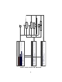
Figure 2: Overview of the GTgui data object hierarchy
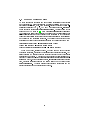
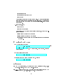
Apart from the data storage classes mentioned above, two additional ones
are part of GTgui: ConditionChip, which stores the GCT channels that are
connected to a condition chip (there are two such chips on both versions of
the GTL board) and TriggerSetupFile, which contains header information
such as author, date and version. All data storage classes are subclasses of
TriggerDataObject which provides properties and methods common to all
those objects: the name of the object, event listener management methods
( 3.3) and a reference to the Context class the data object is part of (see below). Figure 2 gives a visual overview of the class hierarchy of data storage
objects as a UML diagram.
The very heart of the GTgui program and its most complicated part is the
Context class (or to be precise, its concrete subclasses PrototypeContext and
FinalContext). One instance of this class represents one trigger setup (i.e.
the data contents of one internal frame in GTgui or one XML le) and contains collections of all the data objects present in the setup (implemented as
name!reference hashtables for conditions, prealgos and algos). As mentioned
above some changes to a trigger setup only aect single data objects (`simple'
changes), while others have to be checked against a part of or all the other
objects in the setup (`complex' changes). The Context class (short: `context')
is responsible for all the comlex changes: when the setter method of such a
comlex parameter (e.g. setName(String newName) on a condition) is called on
a data object, that method calls an appropriate method in the context it has
a reference to and thus is a part of (e.g. rename(oldName, newName)). That
context method performs the necessary checks (e.g. comparing the new name to
the names of all the other objects of the same type to ensure uniqueness) and (if
necessary) changes parameters of other data objects aected (e.g. the boolean
expressions of all the prealgos that contain the condition in question). If all
the preconditions are fullled, the context method simply returns and the data
object's setter method writes the new value to its appropriate eld. If anything
goes wrong (e.g. name already in use, invalid name) the context method throws
an exception with a nice error message which eventually is caught by the gui ele9
ment that initiated the complex change (e.g. the routine for the rename button)
and displayed to the user in a message box popup. To be able to distinguish
between dierent causes that make an operation impossible (in order to react in
an appropriate way), a number of dierent exception classes has been written,
the names of which should be self-explaining (e.g. InvalidNameException,
NameInUseException).
The operations the context is responsible for include:
Renaming of an object: see above
Moving of an object to a dierent chip: if e.g. a prealgo should be moved
to a dierent chip (by changing its chip number parameter), not only
the prealgo itself has to be moved, but also the conditions it uses in its
boolean expression, since these objects have to be computed on the same
chip. Therefore a number of preconditions have to be checked for: Is space
available on the new chip to acommodate all the objects? Are enough
ouput pins available on the target chip to maintain prealgo connections
to all the algo chips necessary? Are all the input channels available the
conditions involved require? Are the conditions in use by another prealgo
on the original chip (`shared' conditions), which makes it necessary to
duplicate those conditions | the context's move(Prealgo) method will
try to make the operation possible, if it nevertheless fails to do so, again
an appropriate exception is thrown.
Adding or removing an object to/from an algo's or prealgo's boolean expression: When the user alters a boolean expression (e.g. by adding another object) the request() context method checks whether that object
exists, is connected to the requesting object and not in use by another
object. If it is already in use, the user is asked whether he wants to share
those objects between the objects that want to use it, or duplicate it instead and use intependent clones of the requested object for the various
requesting objects (in this case of course several preconditions have to be
fullled, e.g. space available).
Duplicating an object: in this case, the context duplicate() method tries
to generate a new unique name and checks for available space, input and
output connections.
Adding a new object to the context: again, the context add() methods
have to check for available resources and connections before adding the
object to the appropriate collection.
Removing an object from the context: this might e.g. fail if that object is
still in use (i.e. part of a boolean expression)
To sum up the principle: simple parameter changes (that aect only one
data object, e.g. one condition) are processed by that data object on its own,
10
whereas complex changes (add, remove, rename, request for boolean expression,
release from boolean expression, move, duplicate) are passed on to the context
object the data object in question is part of (i.e. has a reference to). That
appropriate context method checks for all the preconditions necessary; if everything is fullled, it performs necessary changes to other data objects involved
and returns. If some preconditions are not fullled and all eorts to fulll those
preconditions fail, the context throws an exception of appropriate type with a
nice error message which is eventually displayed to the user. In some cases, the
routine catching that exception might also display a question to the user (e.g.
whether he/she wants to share or clone a condition that is in use by more than
one prealgo) and again call a context method with the user answer to perform
the operation.
A more detailed description of these processes can be found in the javadoc
documentation of the methods involved (see especially class PrototypeContext)
which can be found on the GTgui project web page (see appendix C for URL).
3.3 Graphical User Interface
The GTgui program is an MDI (multi document interface) application: several trigger setup les can be opened simultaneously in an application main
frame. While the main frame with the menus and toolbars is implemented in
class GTgui, one internal frame with its detail display widgets is laid out in
the abstract class GTguiDocumentView and its concrete subclasses PrototypeGTguiDocumentView and FinalGTguiDocumentView (for prototype- and nal
operating modes respectively).
Since the elements of a trigger setup (algos, prealgos, conditions) are linked to
each other in a tree-like manner, a custom tree widget was chosen to display an
overview of those elements: Conditions are displayed as child elements of the
prealgos that use them in their boolean expression (or as children of the chip
they reside on in case they are unused) and prealgos as children of the chips they
reside on. Those chips are children of a root element that represents the overall
trigger setup (i.e. the header data). In prototype operating mode, there is an
additional hierarchy level: the algorithms. For the sake of simplicity, algorithms
were not included in the same tree view but in an extra tree widget (in nal
mode, this third level is not present, therefore the extra tree is simply omitted
and prealgos renamed to algos, see 3.4). These trees are displayed in the left half
of each internal frame with the algo tree on top and the prealgo/condition tree
at the bottom. If the user clicks on one of the tree nodes, a panel is displayed in
the \detail area" on the right which displays all the parameters of the selected
object and provides inputs to alter them. This is the basic concept of the GTgui
user interface: a tree widget displaying an overview of the setup elements in the
left half, and detailed information panels that are displayed on a user selection
of a tree node in the right half of an internal frame, which represents one trigger
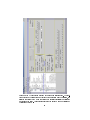
setup. (See gure 3)
11
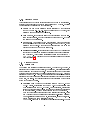
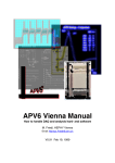
Figure 3: The GTgui program screen with an example trigger setup. The treetable widget on the left shows an overview of the algorithms and conditions, the
selected condition (a two muon condition with spatial correlation) is displayed
in detail on the right. Angle requirements for the second muon are trivial and
therefore not shown
12
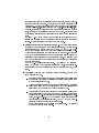
Figure 4: Detailed display of a two particle calorimeter condition
Each data object that has to be displayed (as a tree node, and in a detailed panel on selection of the node) implements the Displayable interface,
which declares (amongst others) a getPanel() method. Displayable data objects implement that method to return an appropriate panel object initialized
with the data stored in the displayable data object and congured to interact
with that object if the user alters that data. A custom panel class has been
written for every data object to display its data in an intuitive way. To display and alter the data stored e.g. in a ConditionChip object, an instance of
ConditionChipPanel is used. Since algos and prealgos contain a similar set
of parameters, only one class (TriggerBooleanCompositionObjectPanel had
to be written, which adapts itself according to the object type passed to its
constructor.
Since the subclasses of Condition share common parameters (such as name,
particle and type attributes as described in the previous chapter), while other
sets of parameters dier in each condition subtype or the same set of parameter
types has to be displayed several times, the complete panels needed for each condition subtype are assembled from modular subpanels: For a CaloSimpleCondition with 2 particles (regardless of the particle type), the total panel consists
of one ConditionPanel on the top (this is true for every condition subtype) followed by two instances of CaloSimpleConditionPanel, each of which displays
the parameters for one calorimeter trigger particle. Figure 4 shows the resulting
total panel.
A CaloWscCondition contains the same information as a two-particle CaloSimpleCondition, plus spatial correlation parameters. Thus the total panel for
such a condition is assembled by simply adding one CaloWscConditionPanel
to the setup described above, which adds displays for the spatial correlation parameters. Assembling is performed by the \-TotalPanel" classes, one of which
has been written for every subclass of Condition: for instance, CaloSimpleTotalPanel provides one ConditionPanel and 1-4 CaloSimpleConditionPanel,
13
depending on the number of particles a CaloSimpleCondition denes. To
save system memory, only one object of each \-TotalPanel" class is instantiated for one GTgui internal frame, regardless of the number of conditions
of the corresponding type present in that trigger setup; the same is true for
TriggerBooleanCompositionObject- Panel. These single instances are held
by the internal frame class GTguiDoc- umentView. When a condition, prealgo
or algo has to be displayed, i.e. if the user selects the tree node corresponding
to that object, the following procedure is executed:
The TreeSelectionListener that listens to the current tree widget (implemented in GTguiTreeTable and GTguiTree) determines the selected
TreeNode object and uses its getUserObject() method to retrieve the
data object associated with it.
If that data object implements the Displayable interface (which currently
all data objects do), its getPanel() method is invoked
That method obtains the singleton instance of the appropriate total panel
from the current GTguiDocumentView and calls its setCondition() or
setTriggerBooleanCompositionObject() method, passing a reference
to itself
The total panel (which previously was used to display a dierent data
object of the same type) now rearranges (i.e. adds/removes them if dierent numbers of subpanels are needed in case of CaloSimpleCondition or
MuonSimpleCondition) its subpanels as economically as possible, updates
the values to display to the ones provided by the calling data object and
congures the subpanels to interact with that object
The getPanel() method now returns the fully congured total panel to
the TreeSelectionListener, which displays the panel in the right half
of the current internal frame
This strategy was designed to minimize memory and CPU usage and make
expansion to additional condition subtypes possible in the future. For additional
information, see the GTgui javadoc programmer's reference.
Apart from this basic concept, a number of minor gui features has been
written for increased ease of use:
Toggle Button Arrays for easy input of the angle trigger masks using
mouse drag gestures
Collapsable panels to hide less important parameters (angle masks) if they
are set to trivial values (always trigger)
Tooltips to display additional data (such as the angle range of one button
in a toggle button array)
14
Custom icons to visually distinguish the data objects in the overview trees
and indicate shared objects (\sharing hand icon")
Tree-Table widget: an expanded tree widget that displays several columns
per row (collapsing and expanding them together with the tree nodes) to
display overview information for each trigger data object (such as condition type and energy thresholds)
Scale les: Parameters are internally handled and stored as bit codes
(this is due to the fact that the trigger hardware uses these bit codes
as well); to simplify parameter input, the bit codes are translated to the
physical quantities they represent (such as 100 GeV/c or 90 degrees) in
the GUI using XML \scale les" which list the quantities to map to each
bit code and are read in by the program. If the mapping of those bit
codes is changed in the future (as is foreseen), the scale les have to be
re-written and the GTgui program has to be set to use the new ones using
an appropriate dialog window (Menu \Options", Item \Change Scale File
Locations"). For a description of the syntax of the scale les, see B.
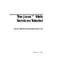
3.4 "Prototype" and "Final" Modes
As mentioned above, an \Abstract Factory" design pattern (as described in [7];
the terminology used in this document is taken from that source) has been implemented to hide the concrete implementations of operating mode dependent
classes from the rest of the program and ensure consistent use of those classes
throughout the code.
Class GTguiAbstractFactory provides factory method denitions needed
for creating those components that dier in the prototype (6U board) and nal
(9U board) operation mode. The procedure for obtaining one of the concrete
products is as follows:
1. congure GTguiAbstractFactory using configure(boolean usePrototype) (if this is omitted, the abstract factory is congured to use nal
mode as default). This is currently done using the user input from the
dialog window that is displayed at program startup, see GTgui.main().
2. obtain the conrete factory by using getGTguiFactory(). This will return an instanceof PrototypeGTguiFactory (if usePrototype == true)
or FinalGTguiFactory (if usePrototype == false). As soon as one instance of the concrete factory has been returned it is impossible to change
the factory conguration. This is to ensure consistent prototype or nal
mode throughout one instance of the GTgui program.
3. obtain the conrete products as needed by calling the get...-methods (e.g.
getContext(), get XMLAdapter(), ...) specied in GTguiAbstractFactory on the concrete factory otained in the previous step. That conrete
15
factory will return those conrete products that are suitable for the operating mode it is named after (see PrototypeGTguiFactory and FinalGTguiFactory for details)
All conrete factory and concrete product classes have been placed in package gt.gtgui.factory, their constructors have been declared package private.
This is to ensure that no conrete factory or product can be directly instantiated without using the concrete factory class returned by this abstract factory
(which would allow inconsistent use of dierent operation mode conrete products within the code).
Currently not all abstract products have dierent implementations for the
two operation modes (e.g. XMLPrototypeAdapter and XMLPrototypeOutputter
which are used in both operation modes). This is due to the fact that exact specications for nal mode were partly not available by March 2005, when version
1.0 of this project was nished. If in the future dierent classes for nal mode
become necessary, those classes have to be written and FinalGTguiFactory has
to be changed to return those classes instead of the current ones.
Amongst a number of minor dierences (ranges for parameters, dierent
numbers of hardware parameters needed), there is one major dierence between
the two operating modes: whilst conditions are combined to prealgos and prealgos to algos in prototype mode, there are only conditions and algos in nal
mode, i.e. one level of boolean combination is omitted. Since the prototypemode prealgos actually are equivalent to nal mode algos (as being a boolean
combination of conditions), the same class (Prealgo) is used to represent these
two entities. The Algo class and the routines involved in handling that class
simply are not used in nal mode (the algorithm tree is not displayed either).
While this is the simplest solution, the user will not notice that \trick", since
in every output to the user the word \prealgo" is replaced by \algo" - the developer of course should be aware of this fact to avoid confusion.
What's more, FinalContext, the nal mode concrete product implementing
the abstract product \Context" basically extends PrototypeContext overriding
all methods not needed in nal mode (such as algo handling methods) with
empty method bodies or dummy routines.
16
Figure 5: Abstract Factory pattern class diagram
17
GTguiAbstractFactory
PrototypeGTguiFactory
...
<<getter>>+getXMLAdapter() : XMLAdapter
<<instantiates>>
<<getter>>+getContext() : Context
<<getter>>+getGTguiDocumentView( parent : GTgui, context : Context ) : GTguiDocumentView
<<getter>>+getXMLOutputter() : XMLOutputter
FinalGTguiFactory
<<getter>>+getXMLAdapter() : XMLAdapter
<<instantiates>>
<<getter>>+getContext() : Context
<<getter>>+getGTguiDocumentView( parent : GTgui, context : Context ) : GTguiDocumentView
<<getter>>+getXMLOutputter() : XMLOutputter
...
...
+configure( usePrototype : boolean ) : void
+usePrototypeMode() : boolean
<<getter>>+getGTguiFactory() : GTguiAbstractFactory
<<getter>>+getGTguiDocumentView( parent : GTgui, context : Context ) : GTguiDocumentView
<<getter>>+getContext() : Context
<<getter>>+getXMLAdapter() : XMLAdapter
<<getter>>+getXMLOutputter() : XMLOutputter
-_usePrototype : boolean = false
-factory : GTguiAbstractFactory = null
FinalGTguiDocumentView
PrototypeContext
FinalContext
Context
PrototypeGTguiDocumentView
GTguiDocumentView
XMLPrototypeOutputter
XMLOutputter
XMLPrototypeAdapter
XMLAdapter
GTgui
3.5 Input and Output
In order to keep the program easily extensible for future I/O demands, all concrete classes involved in data input/output have been separated from the rest
of the code using abstract interfaces. Currently, the only format supported is
an XML le structure (for a specication of le syntax, see [8], example les
are available for download on the GTgui page, see C), while in the future a
connection to a relational database might become necessary.
All future input classes should implement the interface Adapter, which denes methods for retrieving the data objects described in chapter 3.2 and a
method to retrieve any error messages encountered during data source parsing.
Any implementing class is expected to instantiate the data objects necessary
to hold the data stored in the data source that is being dealt with and initialize these objects with the data extracted from that source. All data sould be
checked against simple validity rules (e.g. a min{max ranges). The Context
class denes a method initialize(Adapter a), to which the adapter object
should be passed after full parsing of the data source. That initialization method
will then retrieve the GTgui data objects from the adapter object, add them to
its internal data elds and check for more complex rules (i.e. those that aect
more than one data object, see 3.2).
As for the XML le format mentioned above, this work is done by class
XMLPrototypeAdapter which does not implement Adapter directly, but its
subinterface XMLAdapter, which adds a parseFile(java.io.File) method declaration. As its name indicates, that class was designed for prototype operating
mode, but since the nal mode input syntax currently just slightly diers from
the prototype mode syntax, the same class is re-used in nal mode (if a different XML syntax than proposed by the authors of this project has to be
used in nal mode in the future, a class XMLFinalAdapter should be written
implementing the new syntax and FinalGTguiFactory should be congured
to return the new class instead of the old one). Quite the same is true for
the output classes: XMLOutputter is the abstract interface declaration (there
is no base interface Outputter, since this is not necessary) which denes a
single method writeToFile(Context, File): the context object to output is
passed to that method together with the le object it should be written to.
XMLPrototypeOutputter is the implementing class, which again is currently
used for both operating modes and could be replaced by a dierent nal mode
class in the future.
The implementation of the concrete I/O classes that read and write the XML
syntax dened in [8] is pretty straightforward and tedious. This is due to the
fact that according to that denition certain tags (child-tags in the <algos>,
<prealgos> and <conditions> sections) have arbitrary tag names (which
represent the names of the algos, prealgos and conditions respectively). This
makes the use of XM LSchema or DataBinding technologies impossible. All
syntax checking and data extraction routines were implemented from scratch.
18
Context
...
+request( prealgonames : String[], algo : Algo ) : void
+release( prenames : String[], algo : Algo ) : void
+add( pre : Prealgo, autoShareConditions : boolean ) : void
+remove( pre : Prealgo ) : void
+move( pre : Prealgo ) : void
+duplicate( in : TriggerDataObject ) : TriggerDataObject
<<getter>>+getAlgos() : Algo[]
<<getter>>+getPrealgos() : Prealgo[]
<<getter>>+getConditions() : Condition[]
+initialize( a : Adapter ) : void
...
Adapter
<<getter>>+getTriggerSetupFile() : TriggerSetupFile
<<getter>>+getConditionChips() : ConditionChip[]
<<getter>>+getAlgos() : Algo[]
<<getter>>+getPrealgos() : Prealgo[]
<<getter>>+getConditions() : Condition[]
<<getter>>+getErrorMessages() : String
XMLOutputter
+writeToFile( context : Context, file : File ) : void
XMLPrototypeOutputter
-con : Context
-doc : Document
XMLAdapter
+parseFile( file : File ) : void
+writeToFile( context : Context, file : File ) : void
...
XMLPrototypeAdapter
-file : File
-doc : Document
-errorMessages : String = new String()
...
+parseFile( file : File ) : void
<<getter>>+getErrorMessages() : String
<<getter>>+getTriggerSetupFile() : TriggerSetupFile
<<getter>>+getConditionChips() : ConditionChip[]
<<getter>>+getAlgos() : Algo[]
<<getter>>+getPrealgos() : Prealgo[]
<<getter>>+getConditions() : Condition[]
...
Figure 6: Classes and interfaces involved in I/O
19
3.6 Boolean Expression Parser
To check user inputs of prealgo and algo boolean expressions for syntactical
and contextual (i.e. using conditions in a prealgo expression that do not exist) errors at input time, a top-down recursive-descend parser for boolean expressions containting AND, OR, NOT and ( ) (operators are case-insensitive)
was implemented in class BooleanExpressionParser. An introduction to this
parser type may be found in [9]. Every TriggerBooleanCompositionObject
(i.e. prealgos and algos) has a reference to an instance of the parser class and its
setExpression(String) method passes the new expression on to the parser for
validation before calling appropriate context routines (request() or release())
and writing the new expression to its eld. The parser checkes whether a given
expression is a valid boolean expression according to the following grammar:
<expression> ::= <term> | <expression> `OR' <term>
<term> ::= <factor> | <factor> `AND' <term>
<factor> ::= `(' <expression> `)' | v | `NOT' <factor>
where v is a valid, existing operand. Operand names must not contain
whitespace characters, otherwise the expression will be considered invalid. Any
string delimited by whitespace or round brackets that is not one of the operators
is considered an operand. Whether or not this operand is valid/existing is determined by calling the parent TriggerBooleanCompositionObject's isValidOperand() method. If the expression is valid, setExpression(String) returns
true, otherwise it returns false and the error message can be obtained using
getErrorMessage(). The error message will contain an explanation and the
invalid expression with an error indicator below it.
20
A
User's Manual
A.1 Startup Window
A.1.1
1.
Menubar
File
New
Open
2.
Creates a new le that is completly empty apart from default values
for the le header information and the connected input channels for
the condition chips (see A.3).
Opens a le chooser dialog that allows browsing local directories for
a le to open. Only .xml les with a certain syntax (see thesis by
Alexander Nentschev [8]) may be opened. If parts of the .xml le
are corrupt but parts are not, the program will try to read the valid
parts and notify the user about the location of errors in the le.
Save
If the le has not been newly created, it is saved with its last used
name. If it has been newly created the user hast to choose a name
for the le.
Save as
Opens a le browser that lets the user change the directory to save
the le to as well as its name.
n.b.: only les with the tag .xml can be reopened
Close
Closes the current le. If it has not been saved before, user will be
asked if he/she wants to do so.
Exit
Exits the program. If some of the les that have been opened during
this session have not been saved yet, the user will be asked if he/she
wants to do so, before exiting the program.
Edit
Delete
Rename
Deletes either algorithms, prealgorithms, or conditions when they
are marked in the tree below. It is neither possible to delete prealgorithms that are used in the boolean expression of an algorithm nor
conditions that are used in the boolean expression of a prealgorithm.
Algorithms may always be deleted.
Allows the user to rename TriggerDataObjects. Only names containing the characters: a-z, A-Z, 0-9, ` ' (no whitespace) are allowed.
Renaming can also be started by triple-clicking the object to rename
in the tree view.
21
Add Algorithm
Opens an AlgoPanel (see A.2) with additional Ok and Cancel buttons, where the user can create his/her algorithm. If valid, the algorithm will be added after pressing the Ok button and discarded
when pressing the Cancel button.
Add Prealgo
Opens a PreAlgoPanel (see A.3) with additional Ok and Cancel
buttons, where the user can create his/her prealgorithm. If valid,
the prealgorithm will be added after pressing the Ok button and
discarded when pressing the Cancel button.
Add Condition
Opens a ConditionPanel with additional Ok and Cancel buttons
and default values, that can of course be changed by the user. After
pressing the Ok button the condition will be added to the appropriate
condition chip. Selecting the newly created condition on the prealgo
tree (see A.3), will allow the user to enter detailed information.
3.
Here the user can change the scale les of any conditions. A
dialog window will open where all the scales used in the GTgui program
are listed. Pressing the choose button on the right of the dialog will open
a le chooser dialog where the user can select a new .xml le where the
scale information is stored with a certain syntax (see B).
Options
A.1.2
Toolbar
Provides the same functionality as the menubar. There are tooltips explaining
what function an icon has. The tooltips will be shown when placing the mouse
pointer on an icon and not moving it for a short time.
A.2 Algorithm Window
When creating a new le or opening an existing one, an internal frame that
is separated into an upper and lower window is shown. The upper window is
called the algorithm window (see A.2), the lower one the prealgo window (see
A.3).
As there are no prealgos in the nal operating mode anymore, algorithms become what prealgos are in the prototype operating mode (boolean expressions
of conditions). This means in the nal operating mode conditions are directly
grouped into algorithms. Also the design of the GTL-9U board suggests this,
because there are no algorithm chips any longer. As a consequence there is also
no algorithm window in the nal operating mode.
A.2.1
Algorithm Tree
The left part of the Algorithm Window displays a tree containing all the algorithms that are dened in the le. Selecting an algorithm in the tree, will
display its data in an AlgoPanel on the right.
22
A.2.2
Algorithm Panel
After pressing the Edit button several changes can be done to the algorithm.
If valid the changes will be committed after pressing the Ok button. Pressing
Cancel restores the original data of the algorithm.
The name of an algorithm is only restricted by the characters
that may be used (a-z, A-Z, 0-9, ` ', no whitespace) and by the fact, that
algorithm names of course must be unique.
The user can select on which algorithm chip the algorithm should be stored. Each of the algorithm chips on the GTL-6U board
can store up to 32 algorithms.
As mentioned above, each algorithm chip has only space
for 32 algorithms (each chip has 32 outputs). Here the Output Nr. of the
algorithm can be chosen. The output numbers range from 0 to 31 on the
rst chip and from 32 to 63 on the second one.
After switching to the edit mode by pressing the
edit button the boolean combination of prealgos that denes the algorithm
can be entered. Valid boolean expressions contain the operators OR /
AND / NOT, round braces and names of existing prealgos as operands
only (see also 3.6).
Name:
Algo Chip Nr.:
Output Nr.:
Boolean Expression.:
A.3 Prealgo Window
A.3.1
Prealgo Tree
The prealgo tree consists of multiple tree nodes. The rst node, the root, is
associated with the setup le and displays, when selected, a TriggerSetupPanel
in the detail view on the right hand side. The second level are the two condition
chips that store conditions and the related prealgos (on the GTL-6U board) or
algorithms (on the GTL-9U board). The next level are the prealgos (respectively
algorithms) that are boolean combinations of conditions that build the top level
of the tree, the leaves. Very useful is also the short description of the objects
shown to the right of the tree.
There are two condition chips on both GTL-6U and
GTL-9U boards. It is recalled that on the GTL-9U board algorithms are
what prealgos are on the GTL-6U board. As a consequence, prealgos are
located on these condition chips in the prototype version and algorithms
in the nal version. The same concept is used in the GTgui program.
Each of the condition chips gets input from calorimeter channels. There
are 7 dierent types of calorimeter channels: `Non-isolated Electron/
Gamma', `Isolated Electron/Gamma', `Central Jet', `Forward Jet', `Tauagged Jet', `Energy Summaries', `Jet Counts'.
The GTL 6U-board can be connected to four of these channels. The rst
Condition Chip
23
condition chip will have connections to all but the last, the second condition chip to all but the second. Let us use an example to understand this
better: if e.g. the input channels of the board are set to 1.`Non-isolated
Electron/Gamma', 2.`Isolated Electron/Gamma', 3.`Energy Sums', 4.`Jet
Counts', it will not be possible to dene a jet counts condition on the rst
chip, as this input channel is not connected to the chip. Also trying to set
up a isolated electron/gamma condition on the second chip will cause an
error.
On the GTL-9U board things become easier as it is connected to 10
calorimeter channels and both condition chips are connected to all these
inputs. So every condition can be set up on both chips.
Prealgos are very similar to algorithms. They are a valid boolean
expression of conditions, with the additional limitation, that only conditions also located on the same chip may be used. On the GTL-6U board
each of the condition chips has 55 outputs to each of the algorithm chips.
This is a further limitation that appears only on this board. If there are
more than 55 prealgos stored on one of the condition chips it will not be
possible anymore to connect it to both algorithm chips. An algorithm chip
that has no connection to a special prealgo cannot store any algorithms
that use this prealgo.
On the GTL-9U things are easier again. No prealgos ! no algorithm
chips ! no problem with connection to algorithm chips. The only limitation here is the number of algorithms that can be stored on a chip, which
is 96.
There are many dierent types of conditions, but they have
some things in common.
Name: each Condition has a name, which is used in the prealgo tree
as well as in the boolean expression of a Prealgo (respectively Algo
in the nal operating mode).
Chip: Conditions are stored on of the two condition chips. A Prealgo
(respectively Algo in the nal operating mode) that contains this
condition must be located on the same condition Chip.
Location: In the prototype operating mode the location management
of conditions has to be done by the user him/herself. The condition
chip is subdivided 2-dimensionally into physical locations like a chessboard, but [a-z] [1-4]. The GTgui program in fact takes care that
each condition has a dierent location, but NOT that some conditions might need more space than just one unit.
In the nal operating mode things are easier again. The location
management is done automatically.
Prealgo
Condition
{
{
{
24
A.3.2
Prealgo Detailview
When selecting an object in the prealgo tree, the prealgo detail view will display
the corresponding GUI Panel on the right hand side.
Triggersetup Panel
after switching to edit mode, by pressing the Edit button, the text elds
will become active and allow changes, that will be stored after the Ok
button is pressed. In case the Cancel button is pressed, none of the changes
will be committed, but the original content of the text elds is restored.
: the author of the le
: the date of the last change to the le
: the version number of the le
: path to the VHDL template les to use, required by
the \GTS" XML ! VHDL conversion porgram (see [8])
: any comments the author wants to add
: arbitrary name for the trigger setup
{ Author
{ Date
{ Version
{ VHDL-Path
{ Comments
{ Setup Name
ConditionChipPanel
The user may choose the dierent inputs to the board here. As mentioned
above on the GTL-6U board there are only 4 input channels available, on
the GTL-9U board 10.
PrealgoPanel
Pressing the Edit button switches to edit mode where the user can change
the boolean expression and the name of the prealgo. The output numbers
and the condition chip can always be altered. After pressing the Ok button
the context will do consistency checks and either commits the changes or
inform the user about errors. Cancel will restore the information like it
was before entering the edit mode.
ConditionPanels
Condition panels always consist of two parts. A Panel on the top that
displays respectively allows user input of general information of the condition. Below there is the special information that distinguishes the dierent
condition types, as well as the color of the frame around the panels.
{ General Information Input
Pressing the edit button will allow altering the name, the location
and also the condition chip on which the condition is located. Of
course with several restrictions. Condition names have to be unique
and contain only valid characters (see above). An existing Condition
can only be moved to the other condition chip if it is not in use by a
prealgo (or algorithm in nal operating mode).
When changing the type of the condition, the general information
will be the same in the new condition. The special information will
be lost!
25
{ Special Information Input
As users of this program are supposed to have at least some computer
experience, most of the input will be self-explaining. There are only
two things that should be mentioned:
muon condition panels and e/gamma condition panels are separated
into two parts. The left part is always shown. The right one only if
the information shown is not trivial (if no special eta or phi sector
is selected). By clicking on the arrow in between the two parts, eta
and phi information can be hidden/shown, but only if the selection
is trivial.
Very often a so called ToggleButtonArray is used for user input of
eta or phi selection. The user can either select single buttons (that
represent a certain angle range, that will be shown via tooltips) or
hold the left mouse button down and move the cursor over several
buttons to select a larger angle range. In some cases their are additional buttons to select/unselect all the buttons, for easier handling.
B
Scale Files XML Syntax
GTgui provides an easy handling of scales for conditions. If in future scales have
to be changed, this will not require editing the source code, because reading the
scales is done buy the class ScaleReader. This class reads the scales from .xml
les that can be located anywhere on your machine (see A.1.1). Essential is
that the syntax of the les is correct. There are three dierent types of scales.
1. nonlinear scales or rather short scales, like:
Calorimeter: Energy
Calorimeter: Phi
Calorimeter: Delta Eta(WSC)
Calorimeter: Delta Phi(WSC)
Muon: Momentum
Muon: Delta Eta(WSC)
Muon: Delta Phi(WSC)
Muon: Quality
Missing Transversa Energy: Phi
These scales are read from the ScaleReader by reading the content of the
child tags lowedge, and transforming them into scale items. The number
of the lowedge child tags and the resulting length of the scale is checked
by the ScaleReader.
2. pseudo signed scales, like:
26
Calorimeter: Eta
Calorimeter: Forward Jet Eta
Muon: Eta
These scales are always symmetric around zero. To avoid inconsistencies
only the positive half of the scale is stored in the .xml le. The scale items
are again read from the content of the child tags lowedge. Length checks
are performed.
3. linear scales, like:
Muon: Phi
Energy Sums: Energy
These scales have to contain three dierent child tags, that have the following function:
emin gives the minimum of the scale
emax gives the maximum of the scale
increment gives the increment of the linear scale and as a result also
the length.
C
Related Web Pages
GTgui project homepage:
http://wwwhephy.oeaw.ac.at/p3w/cms/trigger/globalTrigger/software/
setup software.html
Source and build downloads, CVS information, example les, developer
documentation
Global Trigger homepage:
http://wwwhephy.oeaw.ac.at/p3w/cms/trigger/globalTrigger
Institute for High Energy Physics (Hephy), Vienna:
http://wwwhephy.oeaw.ac.at
References
[1] The CMS Collaboration, The Trigger and Data Acquisition Project, Vol. I:
The Level-1 Trigger, CERN LHCC 2000-038 (2000)
[2] C.-E. Wulz: \Concept of the CMS First Level Global Trigger for the CMS
Experiment at LHC", Nucl. Instr. and Meth. A473 (2001) 231
27
[3] A. Taurok et al., \Implementation and Synchronisation of the CMS First
Level Global Trigger for the CMS Experiment at LHC", Nucl. Instr. and
Meth. A473 (2001) 243
[4] Very High Speed Integrated Circuit Hardware Description Language
(VHDL), Standard IEEE-1076 (1993)
[5] Extensible Markup Language (XML), http://www.w3.org/XML
[6] Sun Microsystems, http://java.sun.com/
[7] Erich Gamma, Richard Helm, Ralph Johnson, John Vlissides: "Design Patterns. Elements of Reusable Object-Oriented Software"
Addison-Wesley Professional Computing Series (1998)
[8] Alexander Nentschev: \Development of a Set-Up Software for the Global
Trigger of the CMS-Experiment at the LHC at CERN"
unpublished diploma thesis, Vienna University of Technology (2004)
[9] Robert Sedgewick: \Algorithms"
Addison-Wesley Publishing Company (1983)
28