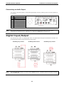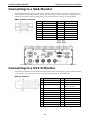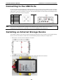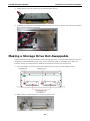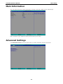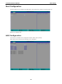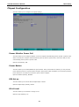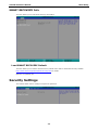
1
V2616A Hardware User’s Manual Second Edition, February 2015 www.moxa.com/product © 2015 Moxa Inc. All rights reserved. V2616A Hardware User’s Manual The software described in this manual is furnished under a license agreement and may be used only in accordance with the terms of that agreement. Copyright Notice © 2015 Moxa Inc., All rights reserved. Trademarks The MOXA logo is a registered trademark of Moxa Inc. All other trademarks or registered marks in this manual belong to their respective manufacturers. Disclaimer Information in this document is subject to change without notice and does not represent a commitment on the part of Moxa. Moxa provides this document as is, without warranty of any kind, either expressed or implied, including, but not limited to, its particular purpose. Moxa reserves the right to make improvements and/or changes to this manual, or to the products and/or the programs described in this manual, at any time. Information provided in this manual is intended to be accurate and reliable. However, Moxa assumes no responsibility for its use, or for any infringements on the rights of third parties that may result from its use. This product might include unintentional technical or typographical errors. Changes are periodically made to the information herein to correct such errors, and these changes are incorporated into new editions of the publication. Technical Support Contact Information www.moxa.com/support Moxa Americas Moxa China (Shanghai office) Toll-free: 1-888-669-2872 Toll-free: 800-820-5036 Tel: +1-714-528-6777 Tel: +86-21-5258-9955 Fax: +1-714-528-6778 Fax: +86-10-6872-3958 Moxa Europe Moxa Asia-Pacific Tel: +49-89-3 70 03 99-0 Tel: +886-2-8919-1230 Fax: +49-89-3 70 03 99-99 Fax: +886-2-8919-1231 Table of Contents 1. Introduction ...................................................................................................................................... 1-1 Overview ........................................................................................................................................... 1-2 Package Checklist ............................................................................................................................... 1-2 Product Features ................................................................................................................................ 1-2 Hardware Specifications ...................................................................................................................... 1-2 Hardware Block Diagram ..................................................................................................................... 1-5 2. Hardware Introduction...................................................................................................................... 2-1 Appearance........................................................................................................................................ 2-2 Dimensions ........................................................................................................................................ 2-3 LED Indicators .................................................................................................................................... 2-3 Real Time Clock .................................................................................................................................. 2-4 3. Hardware Connection Description ..................................................................................................... 3-1 Installing the V2616A .......................................................................................................................... 3-2 Wiring Requirements ........................................................................................................................... 3-2 Connecting the Power .................................................................................................................. 3-3 Grounding the Unit ...................................................................................................................... 3-3 Connecting Data Transmission Cables ................................................................................................... 3-3 Connecting to the Network ........................................................................................................... 3-3 Connecting to a Serial Device ....................................................................................................... 3-5 Installing a CFast Card ........................................................................................................................ 3-5 Digital Input/Output ............................................................................................................................ 3-6 Connecting to a VGA Monitor................................................................................................................ 3-7 Connecting to a DVI-D Monitor ............................................................................................................. 3-7 Connecting to the USB Ports ................................................................................................................ 3-8 Installing an Internal Storage Device..................................................................................................... 3-8 Making a Storage Drive Hot-Swappable ................................................................................................. 3-9 Upgrading the Memory Module ........................................................................................................... 3-11 Installing the Mini PCIe Module ........................................................................................................... 3-12 4. BIOS Setup........................................................................................................................................ 4-1 Entering the BIOS Setup...................................................................................................................... 4-2 Main Information ................................................................................................................................ 4-3 Advanced Settings .............................................................................................................................. 4-3 Boot Configuration....................................................................................................................... 4-4 HDC Configuration ....................................................................................................................... 4-4 Video Configuration ..................................................................................................................... 4-5 Chipset Configuration................................................................................................................... 4-7 PCI Express Configuration ............................................................................................................ 4-8 Hardware Monitor ........................................................................................................................ 4-8 SMART RECOVERY Info ................................................................................................................ 4-9 Security Settings ................................................................................................................................ 4-9 Set Supervisor Password ............................................................................................................ 4-10 Power Settings ................................................................................................................................. 4-10 Turbo Mode .............................................................................................................................. 4-10 Auto Wake on S5 ...................................................................................................................... 4-10 Wake on LAN ............................................................................................................................ 4-11 Boot Settings ................................................................................................................................... 4-12 Boot Type................................................................................................................................. 4-12 PXE Boot to LAN ........................................................................................................................ 4-12 Add Boot Options ...................................................................................................................... 4-12 USB Boot ................................................................................................................................. 4-12 EFI Device First ......................................................................................................................... 4-13 Boot Delay Time........................................................................................................................ 4-13 Legacy ..................................................................................................................................... 4-13 Exit Settings .................................................................................................................................... 4-14 Exit Saving Changes .................................................................................................................. 4-14 Save Change Without Exit .......................................................................................................... 4-15 Exit Discarding Changes ............................................................................................................. 4-15 Load Optimal Defaults ................................................................................................................ 4-15 Load Custom Defaults ................................................................................................................ 4-15 Save Custom Defaults ................................................................................................................ 4-15 Discard Changes ....................................................................................................................... 4-15 Upgrading the BIOS .......................................................................................................................... 4-15 A. Regulatory Approval Statement ........................................................................................................ A-1 1 1. Introduction This chapter gives a general overview of the V2616A computer’s hardware features and specifications. The following topics are covered in this chapter: Overview Package Checklist Product Features Hardware Specifications Hardware Block Diagram V2616A Hardware Manual Introduction Overview The V2616A series of embedded computers are based on the Intel Core i5/i7 processor, and feature 2 RS-232/422/485 serial ports, dual Gigabit Ethernet ports, 3 USB 2.0 ports, and dual VGA/DVI-D video output. V2616A computers have essential compliance with EN 50155, making them ideal for railway and other industrial transport applications. V2616A computers come with a CFast socket that provides ample and secure data buffering or additional storage expansion, as well as 2 hot-swappable storage trays that accept 2.5" solid state or hard disk storage drives, and may be arranged in software RAID 1 arrays to give full data redundancy. Package Checklist Each model ships with the following items: • V2616A embedded computer • 2 storage tray keys • Power cable (CBL-M12FF5PPJ21-BK-15-IP68) • Documentation and software CD or DVD • Quick installation guide (printed) • Warranty card • 2 5-pin terminal blocks NOTE: Please notify your sales representative if any of the above items are missing or damaged. Product Features V2616A embedded computers have the following features: • Compliant with EN 50121-4 • Essential compliance with EN 50155* • IEC 61373 certified for shock and vibration resistance • Two hot-swappable SATA storage trays for 2.5” SSDs or HDDs • 24 to 110 VDC wide range isolated power input • Easy battery replacement • Smart Recovery for manual or automatic system recovery • SynMap for system health monitoring * Moxa defines “essential compliance” to include those EN 50155 requirements that make products more suitable for rolling stock railway applications. Hardware Specifications Computer CPU: • Intel® Core™ i5-3610ME dual-core processor (3M Cache, 2.7 GHz) for V2616A-C5 series • Intel® Core™ i7-3517UE dual-core processor (4M Cache, 1.7 GHz) for V2616A-C7-T series • Intel® Core™ i7-3612QE quad-core processor (6M Cache, 2.1 GHz) for V2616A-C8 series OS (pre-installed): Linux or Windows Embedded Standard 7 System Chipset: Mobile Intel HM65 Express Chipset System Memory: 16 GB capacity, 4 GB pre-installed: 2 slot of 8 GB DDR3-1600 SO-DIMM SDRAM USB: 3 USB 2.0 compliant hosts; 2 with type A connectors supporting system bootup, 1 with M12 connector Storage Built-in: 8 GB CFast to store OS Storage Expansion: 2 hot-swappable storage trays for 2.5” SATA SSD or HDD HDD Support: 1 internal SATA-II storage connector for 2.5” SSD or HDD 1-2 V2616A Hardware Manual Introduction Expansion Slot: 1 full-size/half-size mini PCIe socket with 1 SIM card socket. Mini PCIe socket supports power on/off control Other Peripherals Audio: Line-in, line-out (M12 X-coded) Display Graphics Controller: Intel® HD Graphics 4000 (integrated) VGA Interface: DB15 female connector, max. resolution 2048 x 1536 DVI Interface: DVI-D connector (Chrontel CH7307 SDVO to DVI transmitter), max. resolution 1920 x 1200 Ethernet Interface LAN: 2 auto-sensing 10/100/1000 Mbps ports (M12 X-coded) Serial Interface Serial Standards: 2 software-selectable RS-232/422/485 ports (DB9 male) Isolation Protection: 1.5 kV ESD Protection: 4 kV for all signals Serial Signals RS-232: TxD, RxD, DTR, DSR, RTS, CTS, DCD, GND RS-422: TxDA(-), TxDB(+), RxDB(+), RxDA(-), GND RS-485-4w: TxDA(-), TxDB(+), RxDB(+), RxDA(-), GND RS-485-2w: DataA(-), DataB(+), GND Serial Communication Parameters Data Bits: 5, 6, 7, 8 Stop Bits: 1, 1.5, 2 Parity: None, Even, Odd, Space, Mark Flow Control: RTS/CTS, XON/XOFF, ADDC® (automatic data direction control) for RS-485 Baudrate: 50 bps to 921.6 Kbps (non-standard baudrates supported; see user’s manual for details) Digital Input Input Channels: 6, source type Input Voltage: 0 to 30 VDC at 25 Hz Digital Input Levels for Dry Contacts: • Logic level 0: Close to GND • Logic level 1: Open Digital Input Levels for Wet Contacts: • Logic level 0: +3 V max. • Logic level 1: +10 V to +30 V (Source to DI) Isolation Protection: 3 kV Digital Output Output Channels: 2, sink type Output Current: Max. 200 mA per channel On-state Voltage: 24 VDC nominal, open collector to 30 VDC Connector Type: 10-pin screw terminal block (6 DI points, 2 DO points, DI Source, GND) Isolation: 3 kV optical isolation LEDs System: 1 Power, 1 Storage LAN: 2 100M/Link, 2 1000M/Link Serial: 2 TX, 2 RX Physical Characteristics Housing: Aluminum Weight: 5 kg Dimensions (with mounting ear): 287 x 290 x 101 mm (11.29 x 11.41 x 3.97 in) Mounting: wall Environmental Limits 1-3 V2616A Hardware Manual Introduction Operating Temperature: (without HDD installed) Standard models: -25 to 55°C (-13 to 131°F) Wide temp. models: -40 to 70°C (-40 to 158°F) Storage Temperature: (with SSD installed) -40 to 85°C (-40 to 185°F) Ambient Relative Humidity: 5 to 95% (non-condensing) Anti-vibration: EN 50155 standard Anti-shock: EN 50155 standard Power Requirements Input Voltage: 24 to 110 VDC, M12 connector Note: 24 and 110 VDC are EN 50155 compliant Power Requirements: • 60 W (no SSD/HDD attached) • 2.5 A @ 24 VDC to 0.55 A @ 110 VDC (no SSD/HDD attached) Power Button: On/off (rear panel) Standards and Certifications Safety: UL 60950-1, CSA C22.2 No. 60950-1-07, EN 60950-1 EMC: EN 55022 Class A, EN 61000-3-2 Class D, EN 61000-3-3, EN 55024, FCC Part 15 Subpart B Class A Rail Traffic: EN 50155 (essential compliance*), EN 50121-3-2, EN 50121-4, IEC 61373 Green Product: RoHS, CRoHS, WEEE *Please contact Moxa or a Moxa distributor for details. Reliability Automatic Reboot Trigger: Built-in WDT (watchdog timer) supporting 1-255 second system reset, software programmable Warranty Warranty Period: 3 years Details: See www.moxa.com/warranty Note: These hardware specifications describe the embedded computer unit itself, but not its official accessories. In particular, the wide temperature specification does not apply to accessories such as power adapters and cables. 1-4 V2616A Hardware Manual Introduction Hardware Block Diagram 1-5 2 2. Hardware Introduction V2616A embedded computers are compact and built rugged for use in industrial applications. LED indicators help you monitor performance and identify trouble spots, multiple serial ports allow you to connect a variety of devices for wireless operation, and the reliable and stable hardware platform lets you devote your attention to developing your applications, rather than diddling with low-level APIs and device drivers. The following topics are covered in this chapter: Appearance Dimensions LED Indicators Real Time Clock V2616A Hardware Manual Hardware Introduction Appearance Front View Rear View 2-2 V2616A Hardware Manual Hardware Introduction Dimensions LED Indicators LED Name Power Storage LAN (1, 2) Tx (P1-P2) Rx (P1-P2) L1 LED Color LED Function Green Power is on and functioning normally Off Power is off, or has failed Yellow CFast card/HDD/SSD is transmitting data. Off CFast card/HDD/SSD is not transmitting data. Green 100 Mbps Ethernet mode Yellow 1000 Mbps Ethernet mode Off 10 Mbps or no activity Green Serial ports P1-P2 transmitting data Off Serial ports P1-P2 not transmitting data Yellow Serial ports P1-P2 receiving data Off Serial ports P1-P2 not receiving data Red Programmable. By default, two disks ready to be removed. Blinking Programmable. By default, disks inserted into incorrect storage tray. Off Programmable. By default, two disks inserted into correct storage trays. 2-3 V2616A Hardware Manual Hardware Introduction Real Time Clock The embedded computer’s real-time clock is powered by a lithium battery. We strongly recommend that you NOT replace the lithium battery on your own. If the battery needs to be changed, contact the Moxa RMA service team. ATTENTION There is a risk of explosion if the wrong type of battery is used. To avoid this potential danger, always be sure to use the correct type of battery. Contact the Moxa RMA service team if you need to replace your battery. Caution Dispose of used batteries in a suitable manner. Consult the manufacturer of your battery for more details. 2-4 3 3. Hardware Connection Description In this chapter, we show how to connect the embedded computers to the network and to a variety of common devices. The following topics are covered in this chapter: Installing the V2616A Wiring Requirements Connecting the Power Grounding the Unit Connecting Data Transmission Cables Connecting to the Network Connecting to a Serial Device Installing a CFast Card Digital Input/Output Connecting to a VGA Monitor Connecting to a DVI-D Monitor Connecting to the USB Ports Installing an Internal Storage Device Making a Storage Drive Hot-Swappable Upgrading the Memory Module Installing the Mini PCIe Module V2616A Hardware Manual Hardware Connection Description Installing the V2616A Wall or Cabinet Mounting The V2616A comes with two wall-mounting brackets. Use two screws per side to attach the V2616A to a wall or cabinet. Wiring Requirements This section describes how to connect peripheral devices to the embedded computer. You should read and follow these common safety precautions before proceeding with the installation of any electronic device: • Use separate paths to route wiring for power and devices. If power wiring and device wiring paths must cross, make sure the wires are perpendicular at the intersection point. ATTENTION Do not run signal or communication wiring together with power wiring in the same wire conduit. To avoid interference, wires with different signal characteristics should be routed separately. • Use the type of signal transmitted through a wire to determine which wires should be kept separate. The • Keep input wiring and output wiring separate. • It is advisable to label the wiring to all devices in the system. rule of thumb is that wiring that shares similar electrical characteristics can be bundled together. ATTENTION Safety First! Be sure to disconnect the power cord before installing and/or wiring your V2616A. Wiring Caution! Calculate the maximum possible current in each power wire and common wire. Observe all electrical codes dictating the maximum current allowable for each wire size. If the current goes above the maximum ratings, the wiring could overheat, causing serious damage to your equipment. Temperature Caution! Be careful when handling the unit. When the unit is plugged in, the internal components generate heat, and consequently the outer casing may feel hot to the touch. 3-2 V2616A Hardware Manual Hardware Connection Description Connecting the Power Connect the 24 to 110 VDC power line with M12 connector to the V2616A computer. If the power is supplied properly, the Ready LED will glow a solid green after a 25 to 30 second delay. Grounding the Unit SG: The Shielded Ground (sometimes called Protected Ground) contact is the central pin of the power input connector. Connect the SG wire to an appropriately grounded metal surface. Connecting Data Transmission Cables This section describes how to connect V2616A embedded computers to a network and serial devices. Connecting to the Network Two 10/100/1000 Mbps Ethernet ports using M12 X-coded connectors are located on the rear panel.. ATTENTION There is risk of damage to the M12 X-coded cable due to improper installation or removal. Before you attach an M12 X-coded cable to an Ethernet port on the V2616A, read the instructions carefully. The M12 X-coded cable is designed with locking mechanisms to prevent pin misalignment. Make sure that you properly align the indicator and notches when connecting the cable. Do NOT insert the cable into a port with excessive force. The following figure shows the Ethernet port location on the rear panel. Follow the steps below to connect an M12 X-coded cable: 1. Obtain an M12 X-coded cable. The following table shows the Ethernet connector and cable options. For more information, please contact your local Moxa sales representative. Model Name Type Description CBL-M12XMM8PRJ45-BK-100-IP67 Cable and connector 1-meter X-coded M12-to-RJ45 Cat-5E UTP Gigabit Ethernet cable, 8-pin male M12 connector, IP67-rated. 3-3 V2616A Hardware Manual M12X-8PMM-IP68 Hardware Connection Description Connector Field-installation X-coded screw-in Gigabit Ethernet connector, 8-pin male, M12 connector, IP68-rated. NOTE For best performance and transmission quality, Moxa strongly recommends that you use cables and connectors from Phoenix Contact. 2. Depending on your M12 X-coded cable, orient the cable so that: - The indicator on the M12 X-coded cable aligns with the key notch on the port, or - The notch on the M12 X-coded cable pin core aligns with the notch on the port socket. 3. Connect the M12 X-coded cable to the port. NOTE Do NOT push the M12 X-coded cable into the port with excessive force. 4. Turn to tighten the interlock screw without using a mechanical tool (such as a screw wrench). Aligned Interlock screw 3-4 V2616A Hardware Manual Hardware Connection Description Connecting to a Serial Device Use a serial cable to plug your serial device into the embedded computer’s serial port. Serial ports P1 to P2 have male DB9 connectors and can be configured for RS-232, RS-422, or RS-485 using software. The pin assignments are shown in the table at the top of the next page. DB9 Male Port NOTE RS-232/422/485 Pinouts Pin RS-232 RS-422 RS-485-4W RS-485-2W 1 DCD TxDA(-) TxDA(-) – 2 RxD TxDB(+) TxDB(+) – 3 TxD RxDB(+) RxDB(+) DataB(+) 4 DTR RxDA(-) RxDA(-) DataA(-) 5 GND GND GND GND 6 DSR – – – 7 RTS – – – 8 CTS – – – This is the pin assignment for the computer-side connectors on the V2616A. If you are wiring peripheral-side connectors for a serial cable, you will need to match the pin assignment. Installing a CFast Card The V2616A embedded computers come with a CFast card socket. To install a card, follow these instructions: 1. Disconnect the V2616A from its power source. 2. The CFast socket is located on the center of the rear panel. Unscrew the CFast socket cover. 3. Insert the CFast card into the socket. Make sure you insert it in the correct direction. When finished, fasten the socket cover with screws. 4. If you need to remove the CFast card, simply push the card inward to activate the spring-locking mechanism, and gently remove it once it pops out. ATTENTION The V2616A embedded computer does not support the CFast hot swap and PnP (Plug and Play) functions. Please remember you must cut power first, before inserting or removing the CFast card. In addition, please note that the operating system of the V2616A (Linux or Windows Embedded Standard 7) is stored on the CFast card, so if you change out the card you will need to re-install the operating system. For details on how to automate this, refer to the System Recovery section of the V2616A software manual. 3-5 V2616A Hardware Manual Hardware Connection Description Connecting an Audio Input The V2616A comes with an M12 X-coded audio input/output connector, allowing users to connect a speaker or an earphone. NOTE Pin Audio 1 Line-in, right 2 GND 3 Line in plug-in detected 4 Line-in, left 5 Line-out, left 6 Line out, plug-in detected 7 Line-out, right 8 GND This is the pin assignment for the computer-side connectors on the V2616A shell. If you are wiring peripheral-side connectors for an audio cable, you will need to mirror the pin assignment. Digital Input/Output The V2616A comes with a 6-ch digital input and a 2-ch digital output through a terminal block connector. The pin assignments and the wiring methods are shown below. DI Wiring: Dry Contact NOTE DI Wiring: Wet Contact DO Wiring: Dry Contact If you are using wet contacts, you must connect source to power. In addition, both DI and DO can only be wired as sink types 3-6 V2616A Hardware Manual Hardware Connection Description Connecting to a VGA Monitor The V2616A comes with a D-Sub 15-pin female connector on the front panel to connect a VGA monitor. To ensure that the monitor image remains clear, be sure to tighten the monitor cable after connecting it to the V2616A. The location and the pin assignments of the video outputs are shown in the diagram below. DB15 Female Connector Pin No. Signal Definition Pin No. Signal Definition 1 Red 9 VCC 2 Green 10 GND 3 Blue 11 NC 4 NC 12 DDC2B Data 5 GND 13 HSYNC 6 GND 14 VSYNC 7 GND 15 DDC2B Clock 8 GND Connecting to a DVI-D Monitor The V2616A computer also comes with a DVI-D output for DVI video. Use the cable to connect the DVI-D output to the monitor; if you must rewire a cable, refer to the following table for pin assignments. DVI-D Connector Pin Signal Definition Pin Signal Definition 1 T.M.D.S. Data2- 13 N/C 2 T.M.D.S. Data2+ 14 +5V Power 3 T.M.D.S. Data2 Shield 15 Ground (return for +5V, 4 N/C 16 Hot Plug Detect 5 N/C 17 T.M.D.S. Data0- 6 DDC Clock 18 T.M.D.S. Data0+ 7 DDC Data 19 T.M.D.S. Data0 Shield 8 N/C 20 N/C 9 T.M.D.S. Data1- 21 N/C 10 T.M.D.S. Data1+ 22 T.M.D.S. Clock Shield 11 T.M.D.S. Data1 Shield 23 T.M.D.S. Clock+ 12 N/C 24 T.M.D.S. Clock- HSync, and VSync) 3-7 V2616A Hardware Manual Hardware Connection Description Connecting to the USB Ports On its rear panel the V2616A has an X-coded M12 USB 2.0 port, as well as 2 type A USB 2.0 ports. The hosts can be used for an external flash disk or hard drive for storing large amounts of data. You can also use these USB hosts to connect to a keyboard or a mouse. See the following figures for the locations of the USB ports and the M12 X-coded connector pin assignment. Pin NOTE USB 1 D+ 2 D- 3 +5V 4 GND 5 N.C. This is the pin assignment for the computer-side USB ports on the V2616A shell. If you are wiring peripheral-side connectors for a USB cable, you will need to mirror the pin assignment. Installing an Internal Storage Device The V2616A computer comes with an internal storage tray that allows users to install a 2.5-inch SATA storage device, such as a hard disk or a SSD drive. Take the following steps to install your storage device. 1. Remove the 6 screws from the V2616A’s rear panel. 2. Install the hard disk onto the internal storage kit. Connect the cable and connector. 3-8 V2616A Hardware Manual Hardware Connection Description 3. Fasten the two screws on each side of the hard disk (total of four). 4. Install the storage kit into the V2616A computer. Fasten four screws on the kit, and connect the cable the power onto the V2616A’s main board. 5. Replace the cover onto the back of the computer. Making a Storage Drive Hot-Swappable V2616A computers come with 2 faceplates over the storage drive trays; users may attach storage drives to the faceplates to install additional storage media, such as hard disks (HDD) or solid-state drives (SSD). The following section gives instructions for installing the storage devices into the hot-swap trays. 1. The two faceplates on the front panel of the V2616A may be locked, for extra storage security. 2. Rotate the key counterclockwise to unlock the protection lock. 3-9 V2616A Hardware Manual Hardware Connection Description 3. Pull out the faceplate by unscrewing the thumbscrews in the upper corners, and then remove the plate. Fasten the storage drive to the faceplate flange as shown below, using the two flathead screws that were shipped with your V2616A. ATTENTION To successfully fit the disk into the slot, use the flathead screws to fasten the hard disk to the tray. Do not use the roundhead screws, since they may prevent you from being able to insert the tray into the slot. 4. Carefully align the drive with the drive slot, and gently insert the drive into the computer, taking care that it slides smoothly and firmly into the SATA mounts. 5. When finished, turn the key clockwise to activate the lock and tighten the thumbscrews. Use the same method to install a hard disk in second storage tray. As these are hot-swappable storage trays, you can replace the storage disks while the computer is still powered on. Follow these steps: 1. Push the hot-swap button, located on the lower right of the front panel. 2. Observe the L1 LED indicator (marked in the diagram below). When the LED starts blinking, the system will start to unmount the storage disk. 3. When the LED stops blinking, you may remove the storage drive. 3-10 V2616A Hardware Manual Hardware Connection Description Upgrading the Memory Module V2616A embedded computers come with two 200-pin, DDR3-1600 SODIMM memory slots that can provide up to 16 GB of memory. One 4 GB memory module is installed at the factory. To upgrade a memory module, follow these instructions: 1. Disconnect the V2616A from the power source. 2. Remove the 21 screws that secure the back panel to the case. See the following figure for details. 3. Pull up the back cover of the computer; you will now see the memory sockets on the main board. 4. Carefully remove the module by pushing the latches on both sides of the module, freeing it to be removed. 5. After removing the memory card, install the new module by gently but firmly inserting it into the RAM slot. Before securing the card in place, be sure you have aligned the indentations on each side of the card with the mechanical locks that will hold it in place (shown at right, in the red circles). Once the card is properly aligned, gently push the card down, until it locks in place. You should hear an audible click; before continuing, make sure the latches are firmly in place. 6. When finished, replace the back cover of the V2616A computer. 3-11 V2616A Hardware Manual Hardware Connection Description Installing the Mini PCIe Module The V2616A computer comes with a mini PCIe socket, allowing users to install a mini PCIe module like those used for cellular communications. Follow these steps to installation a module. 1. Pull up the back cover of the computer; you will be able to see the mini PCIe socket on the main board. 2. Install the module into the socket. Fasten two screws on one end of the module. In addition, pull up the SIM card holder beside the socket. 3. Insert the SIM card in the holder by first dropping the holder into place (flush with the board), and then locking it down by sliding it into place. 3-12 V2616A Hardware Manual Hardware Connection Description 4. Connect the cellular antenna cable to the module. 5. Pass the connector of the antenna cable through the antenna hole on the rear panel of the computer. You may use either the W1 or W2 hole. Pass the locking washer over the outer end of the connector first, and then fasten the nut to lock the connector against the face of the computer. NOTE The cellular module, cable, connector, and antenna are not included in the product package, and must be purchased separately. 3-13 4 4. BIOS Setup In this chapter, we describe the V2616A computer’s BIOS settings. The BIOS is a set of input/output control routines for peripherals. The BIOS is used to initialize basic peripherals and help boot the operating system before the operating system is loaded. The BIOS setup allows the user to modify the system configurations of these basic input/output peripherals. All of the configurations are stored in the CMOS RAM, which receives power from a backup battery when the computer is not receiving power from an external power source. The system information will be retained after the system reboots or the power is disconnected. The following topics are covered in this chapter: Entering the BIOS Setup Exit Settings Main Information Exit Saving Changes Advanced Settings Save Change Without Exit Boot Configuration Exit Discarding Changes HDC Configuration Load Optimal Defaults Video Configuration Load Custom Defaults Chipset Configuration Save Custom Defaults PCI Express Configuration Discard Changes Hardware Monitor SMART RECOVERY Info Security Settings Set Supervisor Password Power Settings Turbo Mode Auto Wake on S5 Wake on LAN Boot Settings Boot Type PXE Boot to LAN Add Boot Options USB Boot EFI Device First Boot Delay Time Legacy Upgrading the BIOS V2616A Hardware Manual BIOS Setup Entering the BIOS Setup To enter the BIOS setup utility, press the F2 key while the system is booting up. The main BIOS Setup screen will appear. You will see four options: Continue: Continue to boot up Boot Manager: Select the device to boot up Boot From File: Select the UEFI boot up file SCU: Enter the BIOS configuration. Click SCU to enter the BIOS configuration. When you click SCU, a basic description of each function key will be listed at the bottom of the screen. Refer to these descriptions to learn how to use them. F1: General Help F5/F6: Change Values F9: Setup Defaults F10: Save and Exit ↑↓: Select Item ← →: Select Menu ESC: Exit ENTER: Select or go to Submenu. 4-2 V2616A Hardware Manual BIOS Setup Main Information The main page shows basic system information, including model name, BIOS version, and CPU type. Note: “Processor Type” depends on which product model you are using. Advanced Settings The Advanced Features screen will appear when you select “Advanced” from the main menu. 4-3 V2616A Hardware Manual BIOS Setup Boot Configuration This item allows you to configure the initial status of the Numlock key when the computer boots up. Options: On (default), Off HDC Configuration The host drive controller can be configured for IDE or AHCI mode (default). When AHCI mode is selected, the following screen will appear. 4-4 V2616A Hardware Manual BIOS Setup Serial ATA Port 0 to 4 This setting allows you to display information about the installed drives. AHCI SALP Note that the “AHCI SALP” setting will only appear when AHCI mode is selected. This item allows you to enable aggressive link power management (SALP) in AHCI. SALP enables the host bus adapter to conserve power by directly detecting when a SATA drive is no longer processing information and then immediately shifting it into suspended or sleep mode without waiting for software processes to initiate a power-down process. Host Capability Register bit 26. Options: Enabled (default), Disabled SATA Port 0 to 4—HotPlug This item allows you to enable/disable hotplug capabilities (the ability to remove the drive while the computer is running) for installed storage drives. Options: Disabled (default for Port 0), Enabled (default for Port 1 to Port 4) Video Configuration This item allows you to configure the Internal Graphics Device (IGD) for things like memory allocation (DVMT). 4-5 V2616A Hardware Manual BIOS Setup Internal Graphics Device This option allows you to enable/disable the internal graphics device. IGD—DVMT Pre-Allocated This item allows you to configure the pre-allocated memory capacity of the IGD. Pre-allocated graphics memory is invisible to the operating system. Options: 64 MB (default), 32 MB, 96 MB, 128 MB, 256 MB, 512 MB DVMT is a BIOS solution where “the optimum amount of memory is dynamically allocated and de-allocated as needed for balanced graphics and system performance, through Intel® Direct AGP and a highly efficient memory utilization scheme. DVMT ensures the most efficient use of available system memory resources for maximum 2D/3D graphics performance. IGD—DVMT Size This item allows you to configure the maximum amount of memory DVMT will use when allocating additional memory for the IGD. Options: 256 MB (default), 128 MB, Max IGD—Boot Type This item allows you to select the video device activated during POST. Options: VBIOS Default (default), VGA, DVI 4-6 V2616A Hardware Manual BIOS Setup Chipset Configuration This item allows you to configure the chipset settings. Power ON after Power Fail This item allows you to configure whether or not the computer automatically powers up after a system crash. When set to ON, the computer will automatically power up after a system crash; when set to OFF, it won’t automatically power up after a system crash. Options: ON (default), OFF Power Button This item allows you to enable/disable the power button. If the power button is enabled, you can press the power button to power on or power off the computer. If the power button is disabled, you will need to press the power button for more than four seconds to power off the computer. Options: Enabled (default), Disabled DI0 Set as This item allows you to set the DI0 as Digital Input or Reset. Options: Digital Input (default), Reset# DO-0 Level This item allows you set the DO-0 as high or low. Options: High (default), Low 4-7 V2616A Hardware Manual BIOS Setup DO-1 Level This item allows you set the DO-1 as high or low. Options: High (default), Low. PCI Express Configuration PCIe Speed This item allows you to configure the speed of the mini PCIe interface. Options: Auto (default), Gen1, Gen2 Hardware Monitor This item allows you to view voltage levels, system temperature, and CPU temperature. Note that the voltage values are different for different models. The temperature readings shown on the screen are within ±5% of the actual readings. However, the temperature readings are only valid when the ambient temperature is above 0°C. 4-8 V2616A Hardware Manual BIOS Setup SMART RECOVERY Info This item allows you to view Smart Recovery information. Load SMART RECOVERY Default This item allows you to load the Smart Recovery default value. Refer to the Smart Recovery Website: http://www.moxa.com/product/Smart-Recovery.htm for details Options: Yes (default), No Security Settings This section allows users to configure a supervisor password. 4-9 V2616A Hardware Manual BIOS Setup Set Supervisor Password This item allows you set the supervisor password. Type in the new password, and then retype the password again to confirm. To delete the password, enter Set Supervisor Password using the existing password. Next, leave the new password fields blank, and then press enter. Power Settings The section allows you to configure power settings. Turbo Mode This item allows you to enable or disable the Intel CPU Turbo Boost technology. Options: Enabled (default), Disabled. Auto Wake on S5 This item allows you to configure the computer to wake from S5 status. S5 stands for Soft Off, where the PSU remains engaged but power to all other parts of the system is cut. Auto-wake on S5 schedules a soft-reboot at certain periodic times, which can be specified in the BIOS. 4-10 V2616A Hardware Manual BIOS Setup Options: Disabled (default); By Every Day (user specifies at what time each day the computer will power up); By Day of Month (user specifies which day of each month the computer will power up) Wake on LAN This feature is used to wake the system over the LAN from a remote host. Options: Enabled (default), Disabled. 4-11 V2616A Hardware Manual BIOS Setup Boot Settings The section allows users to configure boot settings. Boot Type This item allows you to enable/disable the quick boot function. Options: Dual Boot Type (default), Legacy Boot Type, UEFI Boot Type PXE Boot to LAN This item allows you to enable/disable the PXE boot to LAN function. Options: Disabled (default), Enabled Add Boot Options This item allows you to add boot order options for new boot devices on and removable devices, such as a USB drive. Options: Last (default), First USB Boot This item allows you to enable/disable USB boot function.. Options: Enabled (default), Disabled 4-12 V2616A Hardware Manual BIOS Setup EFI Device First This item allows you to determine if the EFI device boots first or the legacy device boots first. If enabled, the EFI device will boot first; if disabled, the legacy device will boot first. Options: Disabled (default), Enabled Boot Delay Time This item allows you to configure the delay time during which users can enter a hot key during POST time. Options: 0 Second (default), 3 Seconds, 5 Seconds, 10 Seconds Legacy Normal Boot Menu This item allows you to configure the boot menu. Options: Normal (default), Advance Boot Type Order This item allows you to select the boot order. To change values, use the “-” or “F5” key to move down, and the “+” or “F6” key to move up. Options: Hard Disk Drive (default), CD/DVD-ROM Drive, USB, Others Hard Disk Drive/USB Drive This item allows you to view installed devices, such as hard disk drives, USB drives, and CD-ROMs. For example, if you have inserted a USB drive into the computer, it will appear here. You can view and select boot order in the same type storage. 4-13 V2616A Hardware Manual BIOS Setup Exit Settings The section gives several options for exiting the BIOS environment. Exit Saving Changes This item allows you to exit the BIOS environment and save the values you have just configured. Options: Yes (default), No 4-14 V2616A Hardware Manual BIOS Setup Save Change Without Exit This item allows you to save changes without exiting the BIOS environment. Options: Yes (default), No Exit Discarding Changes This item allows you to exit without saving any changes that might have been made to the BIOS. Options: Yes (default), No Load Optimal Defaults This item allows you to revert to the factory default BIOS values. Options: Yes (default), No Load Custom Defaults This item allows you to load custom default values for the BIOS settings. Options: Yes (default), No Save Custom Defaults This item allows you to save the current BIOS values as a “custom default” that may be reverted to at any time by the “load custom defaults” selection just above. Options: Yes (default), No Discard Changes This item allows you to discard all settings you have just configured. Options: Yes (default), No Upgrading the BIOS This section describes how to upgrade the BIOS. However, note that it is easy to permanently damage the computer when upgrading the BIOS. We strongly recommend that you contact Moxa’s technical support staff for assistance to obtain all the necessary tools and the most up-to-date advice before attempting to upgrade the BIOS on any Moxa device. Step 1: Create a Bootable USB Disk Before upgrading the BIOS, every user should first create a bootable USB RAM drive as a system rescue device. A useful software suite for building USB RAM drives can be found by searching for Rufus, which can then be downloaded and used to create a bootable RAM drive. Take the following steps to create a bootable USB disk using Rufus. 4-15 V2616A Hardware Manual BIOS Setup 1. Start Rufus and then in the “Device” drop-down list select the USB device that you want to use as a bootable disk. 2. Select MBR partition scheme for BIOS or UEFI computers from the “Partition scheme and target system type” drop-down list so it can boot from a legacy BIOS or UEFI. 3. Select FAT (Default) from the “File system” drop-down list. 4. Select 16 kilobytes (Default) from the “Cluster size” drop-down list. 5. Enter a drive name in the “New volume label” input box. 6. Checkmark the Quick format, Create a bootable disk using FreeDOS, and Create extended label and icon files options. 7. Click Start to format and create the bootable USB drive. ATTENTION When you use a USB drive larger than 4 GB, you will need to convert the file system type to FAT32. Step 2: Prepare the Upgrade File You must use the BIOS upgrade installation file to upgrade the BIOS. Contact Moxa’s technical department for assistance. 1. Get the BIOS upgrade installation file. The file name should have the following format: V2616AxxSx.exe (xx refers to version numbers). 2. Copy the file to the Bootable USB Disk. Step 3: Run the upgrade program on the V2616A Computer 1. Reboot the computer, and press F2 while booting up to open the Boot Manager. 2. Select USB Disk as the first boot source, and then press Enter to continue. 3. When the computer finishes booting up, a DOS screen will open. Go to the directory where the upgrade file is located. For example, if the upgrade file is stored in the V2616A folder, type cd V2616A. 4-16 V2616A Hardware Manual BIOS Setup C:\cd V2616A 4. Run the upgrade program by typing 2616A10S6.exe. Note that the upgrade filename may be different for different versions. C:\ V2616A>2616A10S6.exe 5. The upgrade program will run automatically. Wait until the procedure finishes. 6. When the upgrade is finished, the computer will automatically reboot. You may check the BIOS version on Main page of the BIOS Setup ATTENTION Do NOT remove the power supply during a BIOS upgrade, since doing so may cause the system to crash. 4-17 A A. Regulatory Approval Statement This device complies with part 15 of the FCC Rules. Operation is subject to the following two conditions: (1) This device may not cause harmful interference, and (2) this device must accept any interference received, including interference that may cause undesired operation. Class A: FCC Warning! This equipment has been tested and found to comply with the limits for a Class A digital device, pursuant to part 15 of the FCC Rules. These limits are designed to provide reasonable protection against harmful interference when the equipment is operated in a commercial environment. This equipment generates, uses, and can radiate radio frequency energy and, if not installed and used in accordance with the instruction manual, may cause harmful interference to radio communications. Operation of this equipment in a residential area is likely to cause harmful interference in which case the user will be required to correct the interference at his own expense. European Community Warning: This is a class A product. In a domestic environment this product may cause radio interference in which case the user may be required to take adequate measures.