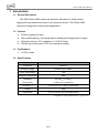
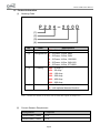
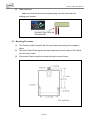
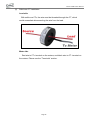
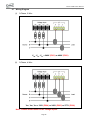
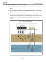
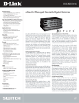
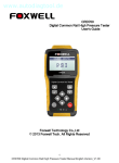
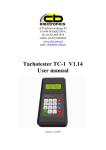
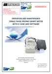
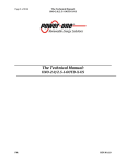
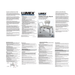
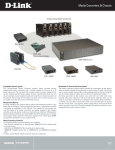
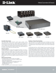
1
Polaris 2000 User Manual 2015/09/30 Version : 1.0us DAE Instrument Corp. http://www.DAEinstrument.com/ Polaris 2000 User Manual Page 2 Polaris 2000 User Manual Polaris 2000 User Manual, 2015, Sep. Copyright © 2015 DAE Instrument Corp. All rights reserved. DAE Controls LLC. 2707 Golfview Dr. 103 Troy Michigan 48084, USA Tel:+1 (248)-635-3708 Fax:+1 (248)-822-8138 e-mail:[email protected] DAE Headquarters 5F, No. 157, Xinhu 1st Road, Neihu District, Taipei 11494, Taiwan, R.O.C. Tel:+886 (02)-2793-6123 Fax:+886 (02)-2793-6150 e-mail:[email protected] Page 3 Polaris 2000 User Manual Safety Precautions Please read these safety instructions before using this equipment. For safety purposes, please observe the following when unwrapping and installing the package: 1. When opening the package, check that the contents have not been damaged during transit. 2. Check to make sure that the product model and the labeling on the outside of the packaging are consistent. 3. This product is designed for and suitable for most electrical power panels. 4. Do not install this product at the openings of ventilation ducts or near heat sources. 5. Make sure that the actual wiring conforms to the wiring diagram designated in this manual. 6. Guard against dust and water damage. 7. Make sure all power sources to be connected to the product have been shut off before installing. 8. If the equipment is used in a manner not specified by manufacturer, the protection provided by the equipment may be impaired. This symbol means double insulation. This symbol means to beware of electric shock, turn off all adjacent sources of high voltage during installation. This symbol means there is risk of danger. The Polaris is a sensitive electrical equipment, care should be taken so that the maximum benefit and performance can be derived from the device. Before cleaning or performing any maintenance on the Polaris, disconnect the device from its auxiliary power source. The input voltage and current should be either turned off or disconnected. Page 4 Polaris 2000 User Manual Cleaning Use a dry cloth or dry brush to wipe away the dust, or use in conjunction with a vacuum cleaner to suck the dust as it is being wiped away. Do not use any water or other liquid cleaning agents. Ventilation Check to make sure that there is sufficient space around the periphery of the Polaris to allow air to circulate. Reposition any extraneous wiring that is on the Polaris. Maintenance Check to make sure that the wiring contacts are tight and making good contact, tighten any terminal screws that may have loosened over time from jarring or vibration. Make sure that the wiring contact of each terminal is not touching or shorting adjacent terminals. Repair Do not attempt to repair the product or modify the circuitry, contact the product representative or a qualified electrical person if the product requires repair or servicing. Page 5 Polaris 2000 User Manual CONTENT 1. Introduction.......................................................................... 7 1.2 General Description ..................................................................................................... 7 1.2 Features ........................................................................................................................ 7 1.3 Certifications ................................................................................................................. 7 1.4 Specifications ................................................................................................................ 7 1.5 Product information ...................................................................................................... 8 2. Installation ............................................................................ 9 2.1 Front Panel.................................................................................................................. 10 2.2 Terminals ..................................................................................................................... 11 2.3 Mounting Procedure ................................................................................................... 12 2.4 Before Installation ....................................................................................................... 13 2.5 Meter Installation ........................................................................................................ 13 2.6 CT Installation ............................................................................................................. 14 2.7 Wiring Diagram ........................................................................................................... 16 2.8 Measuring Multiple Loads with One Meter .............................................................. 17 2.9 Power Supply .............................................................................................................. 18 2.10 Using a Regular 5A Output CT ................................................................................. 18 3. Troubleshooting ................................................................ 19 4. Frequently Asked Questions ............................................ 20 5. Warranty and Return Policy ............................................. 22 6.1 Warranty ...................................................................................................................... 22 6.2 Return Policy............................................................................................................... 22 6. Supplementary Information .............................................. 23 Page 6 Polaris 2000 User Manual 1 Introduction 1.1 General Description The DAE Polaris 2000 meters are electronic kilowatt-hour (kWh) meters designed for permanent connection to an electrical service. The Polaris 2000 meters are designed for three-phase applications. 1.2 Features Revenue-grade accuracy Non-volatile Memory, the stored data is maintained through power outages Optional solid-core CTs available in 5, 50 & 200 Amp Parallel up to three sets of CTs for cumulative reading 1.3 Certifications UL/CUL Listed 1.4 Specifications Item Descriptions Frequency 50/60 Hz Working Voltage Derived from A phase Power Consumption 7VA Measured Parameters kWh Operating -20~50 (-4~122 ) Environment 0~95% non-condensing Accuracy (*) 0.5% from 1% to 100% of rated load Weight 690g Dimensions W 5” x H 6.50” x D 2.24” wall-mount * Based on DAE solid-core CT @ PF=1 Page 7 Polaris 2000 User Manual 1.5 Product Information (1) Ordering Code No. Item Descriptions P20 – Polaris 2000 (1) Series (2) Configurations 2 – 3-Phase, 3 Wire, 480V 3 – 3-Phase, 3 Wire, 240V 4 – 3-Phase, 4 Wire, 120/208V 5 – 3-Phase, 4 Wire, 240/416V 6 – 3-Phase, 4 Wire, 277/480V (3) CT Rating 005 – 5 Amp (*) 050 – 50 Amp 100 – 100 Amp 200 – 200 Amp 400 – 400 Amp 600 – 600 Amp (4) Demand n/a – without optional demand function D – with optional demand function Note : * Please see Section 2.10 which can be used with regular 5A output CTs. (2) Current Sensors Requirement Configuration CT required Three-Phase, 3 Wire 2 CTs Three-Phase, 4 Wire 3 CTs Page 8 Polaris 2000 User Manual 2 Installation The Polaris is a sophisticated energy meter with multiple capabilities and functions. Before installation be sure to read and understand this section and the appropriate wiring diagrams. Installation of this device must be performed by qualified personnel according to these instructions and in conjunction with all applicable electrical codes. DAE Instrument and its representatives assumes no responsibility for any damage or injury resulting from the improper installation of this equipment. WARNING: Please make sure you have read the “Safety Precautions” on the beginning of this user manual before you start installation. Page 9 Polaris 2000 User Manual 2.1 Front Panel 6-digit primary LCD display LED display TX, RX for showing kWh and other parameters Reserved A, B, C Phases A, B, C phase voltage inputs indicator P Watthour test constant indicator Load Load relay status indicator DI Digital input indicator Terminal Cover To cover the terminals Series Polaris 2000 Ordering Code Ordering Code of Polaris 2000 Ordering information Configuration, voltage, max current Page 10 Polaris 2000 User Manual 2.2 Terminals Remove the terminal cover VA, VB, VC, VN Phase A, B, C and N voltages DI+, DI- Setting switch input P+, P- Reserved CT-A+, CT-A- Phase A CT input CT-B+, CT-B- Phase B CT input CT-C+, CT-C- Phase C CT input Terminal Detail (1) Voltage input terminals Use the proper size and wire type as per electrical regulations. Page 11 Polaris 2000 User Manual (2) Other terminals Make sure that the wires are screwed tightly onto the terminals and making good contact. 2.3 Mounting Procedure (1) The Polaris is wall-mounted, drill the screw holes according to the diagram below. (2) Place the Polaris flush against the wall aligning the mount holes of the Polaris with the screw holes. (3) Secure the Polaris using the screws through the mount holes. Page 12 Polaris 2000 User Manual 2.4 Before Installation (1) Check that the ratings and specification of the model to be installed is suitable for its intended application. (2) Verify that the dedicated CT being used is compatible with the type of Polaris. Note that the Polaris cannot be directly used with non-DAE dedicated CTs. See the special application section for using the Polaris with regular 5A output CTs. (3) Verify that the current rating of the dedicated CT being used is suitable for its intended load. (4) Make sure to turn off all power sources to the Polaris and any adjacent power sources before performing the installation. 2.5 Meter Installation (1) Attach the dedicated CTs to the CT terminal with their appropriate phases. (2) Connect the voltage input terminals of the Polaris meter to their corresponding phase voltages from the power source with intermediate fuses. (* Use 18 to 22 AWG, 600V wire for the voltage terminals.) (3) Assemble the CTs onto the corresponding conductors being measured making sure that the direction and orientation of the CTs with wiring are consistent. With solid core CTs, the wire must be threaded through the CT, which would necessitate disconnecting the wire from the load. With split core CTs and clamp type CTs, the CT can be opened and clipped or clamped onto the conductor without the need to disconnect the wiring to the load. Page 13 Polaris 2000 User Manual 2.6 CT Installation Polaris meters only can use the dedicated CT provided by DAE. DAE’s dedicated CTs have two types as the follow descriptions. (1) Split-core CT installation Load side Step 1. Open the split-core CT Step 2. Hoop up the loading wire Step 3. Clipped the split-core CT Meter side Red wire to CT+ terminal on the meters, and black wire to CT- terminal on the meters. Please see the “Terminals” section. Page 14 Polaris 2000 User Manual (2) Solid-core CT installation Load side With solid core CTs, the wire must be threaded through the CT, which would necessitate disconnecting the wire from the load. Meter side Red wire to CT+ terminal on the meters, and black wire to CT- terminal on the meters. Please see the “Terminals” section. Page 15 Polaris 2000 User Manual 2.7 Wiring Diagram (1) 3-Phase, 3 Wire VAB, VBC, VCA = 240V (P203) or 480V (P202) (2) 3-Phase, 4 Wire VAN, VBN, VCN = 120V (P204) or 240V (P205) or 277V (P206) Note : Please install fuses for the voltage inputs. Page 16 Polaris 2000 User Manual 2.8 Measuring Multiple Loads with One Meter (1) The loads must be the same configuration and come from the same power source. (2) Max. 3 loads for each meter; each load needs complete sets of CTs and each CT must be the same rating. (3) The load wire thread through the CTs must be the same direction. The multiple CTs for the same phase of multiple loads must connect to the correct polarity (Red wire to CT+ terminal and black wire to CT- terminal on the meters). e.g. 3-Phase, 3 Wire Wiring Page 17 Polaris 2000 User Manual 2.9 Power Supply The power supply of the Polaris is derived from the voltage input. To provide additional protection for the Polaris, a fuse should be placed between the Polaris and the power source as shown in each of the electrical wiring diagrams. 2.10 Using a Regular 5A Output CT For installations with pre-existing CTs or if larger capacities is required, the user should choose the dedicated 5A CT and connect the user provided CT to the dedicated 5A CT as shown in the diagram below. When using regular CT, the Polaris meters need to set the CT ratio. For example, when using 500A : 5A regular CTs, the CT ratio should set 100. Page 18 Polaris 2000 User Manual 3 Troubleshooting The Polaris meters are fully calibrated and tested before put in stock. The Polaris meters should work normally if installed properly by correctly following our installation guide. If the meter has any problem, please consider the following troubleshooting guides. Problems or Symptoms The LED does not light up. Possible Causes and Solutions (a) Check that the voltage input terminal wiring are connected properly. (b) Check that the fuse and circuit breaker are neither blown nor tripped, respectively. (c) Check to make sure that power is being supplied from the power source to the voltage input. (d) Check that the power source voltage is within the rated power supply. (e) Check to make sure that the enclosure or terminals are not damaged. kWh value is not incrementing. (a) Check that CT wiring to the terminals. (b) Check to make sure that the measured circuit corresponds to its phase. (c) Check to make sure that the power is on for the load circuit being measured. (d) Check the fuse or circuit breaker. (e) Check to make sure that only the L wire passes through the CT, if the N wire is also passing through then remove it from the CT. (f) The CT may be damaged or defective, swap it with another CT for a cross check. If defective or damaged, replace the CT. Page 19 Polaris 2000 User Manual Problems or Symptoms Possible Causes and Solutions Any Voltage input indicators do not (a) Check to make sure that the voltage input light up. terminal wiring is connected properly. (b) Check the voltage input terminals are not damaged. The accumulation of kWh does not (a) Check the CT ratio if use with regular 5A match total consumption. output CT. (e.g. 500A : 5A, the CT ratio = 100) (b) Check to make sure the voltage input is continuously 24 hrs/day. (c) Check the CT wiring direction on load and polarity on meters if parallel 2 or 3 CTs for any phase. When parallel 2 or 3 CTs, the wiring direction and polarity must be the same. 4 Frequently Asked Questions Q. Why the kWh value of a new Polaris is not zero? A. Each Polaris meter must proceed a loading test with a calibration exam before put in stock. The kWh value exists to make sure this unit passes the calibration exam. Q. What is the meaning of 1000imp/kWh? A. It means 1000 pulses will be output for every kWh. Another way of saying it is that 1 pulse is output for every Watt. The P indicator will flash once for every Watt consumed. Q. Does the Polaris meters come with its own CTs? Can I make use of my own CTs? A. The Polaris is basically sold as a kit which already includes the CTs. But it can also be sold standalone without any CT for use as replacement units. The Polaris uses DAE’s dedicated CTs and cannot directly accept neither regular 5A output CTs nor the dedicated CTs from other suppliers. Connecting a regular 5A output Page 20 Polaris 2000 User Manual CT directly will thus damage the Polaris. If a regular 5A output CT is to be connected, it needs to first be connected through a DAE’s dedicated 5A CT. Q. Can the CT lead wire be extended? A. Yes, the CT lead wire can be extended up to 2000 feet. An example of a suitable cable would be the 7958A or the 7957A from Belden cables. It is important to note that the cable is normally sized at 22-26AWG, twisted pair, but make sure to consult your local electrical codes for proper sizing requirements. Q. Can a single CT be used to monitor multiple circuits? A. It is possible to do so if the different circuits share the same phase and power source. The L wire for each circuit must go through the CT in the same direction, and the current rating of the CT in must be higher than the total amperage for all the circuits to be measured. Q. Can a single Polaris be used to monitor two different sub panels? A. It is possible if the two sub panels have the same power source. If the two sub panels do not share the same power source, then two separate Polaris must be used. Q. What will happen if the polarities are reversed for each CT? A. The Polaris only considers the absolute value of the current and disregards the direction; thus, the current and energy values can only be positive. However, we still recommended that the CTs be connected with the correct wiring orientation. Q. I have checked and followed all the troubleshooting guidelines but my problem is still not resolved; what should I do? A. Contact our technical support by phone or email before concluding that the unit is faulty and removing it. Our technical support team will help to diagnose your problem and provide advice on potential fixes. Please see Section 7, “Supplementary Information”, for our contact info. Page 21 Polaris 2000 User Manual 5 Warranty and Return Policy 5.1 Warranty The warranty is effective for a period of five years from the date of shipment. The buyer must inform DAE of the defect within 80 days after the defect is experienced or found. DAE’s responsibility is limited to repair, replacement, or refund, any of which may be selected by DAE in its sole discretion. DAE reserves the right to substitute functionally equivalent new or serviceable used parts. This warranty covers only defects from normal use and does not include the defects due to improper installation, improper maintenance, misuse, neglect, water damage, acts of nature, tornadoes, any alterations or repairs by others not DAE. DAE's liability to the Customer from the sale of DAE's products, whether such liability is asserted on the basis of contract, tort or otherwise, shall not exceed the purchase price paid by Customer for the products claimed. 5.2 Return Policy All returned material must be in good,” as new” and in salable condition. A 20% restocking fee is charged on all RMA’s. Products may not be returned if more than 80 days have elapsed since the shipment date from DAE. Buyer must notify DAE and request a Returned Material Authorization Number (RMA Number) and state the specific reason for return. Unauthorized returns will not be accepted. When requesting an RMA Number please supply the following information: (1) Distributor name and address (2) Model number of meter (3) Original purchase order number (4) Reason for return All paperwork and boxes must be marked with an RMA number issued by DAE. All authorized returned materials must be shipped freight prepaid to DAE. DAE is not responsible for uninsured packages or packages lost by your carrier. RMA's are only valid for 30 days. The buyer will be responsible for all return shipping costs and customs duties. Page 22 Polaris 2000 User Manual 6 Supplementary Information Please add fuses to the voltage input to protect damage from a short circuit. Our contact information US Website: www.DAEcontrols.com US Email: [email protected] US Phone: +1-(248) 635-3708 International Website: www.DAEinstrument.com International Email: [email protected] International Phone: +886-2-2793-6123 Note : This document may change without notice, please check our website for the latest version. Page 23