1
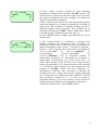
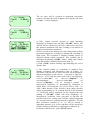
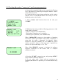
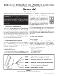
ul.Przybyszewskiego 43
01-849 WARSZAWA
tel. (0-22) 8641934
tel/fax. (0-22) 8349262
www.cbe.com.pl
mail: [email protected]
Tachotester TC-1 V1.14
User manual
Warsaw 01.2007
CONTENTS
INTRODUCTION................................................................................................................................................... 3
TECHNICAL AND METROLOGICAL DATA ...................................................................................................... 4
INSTRUMENT DESCRIPTION ............................................................................................................................. 6
OPERATING GUIDE ............................................................................................................................................. 6
DESCRIPTION OF INSTRUMENT FUNCTIONS ................................................................................................. 7
1. Selection of the method of encoding of the k-factor with the tachograph switches................................................. 7
2. Entry of the “Sn” factor of the driving unit........................................................................................................... 7
3. Entry of the tachotester’s “St” factor .................................................................................................................... 8
4. Entry of the tachotester’s “So” factor ................................................................................................................... 9
5. Measurement of the “k” factor of the electronic tachograph, type 026/10 .............................................................10
6. Measurement of the “k” factor in electronic tachographs, type 1314, 1318, 8400 etc. equipped with a test jack of
“mini Jack” type and in tachographs of type no. 1319 .............................................................................................11
7. Speed simulation with a measurement of distance or the number of imp/rev .......................................................12
8. Measurement of the "n" factor of the rev counter.................................................................................................14
9. Speed of rotation simulation with a measurement of the number of revolutions....................................................15
10. Setting the parameters of the reference diagram.................................................................................................17
11. Drawing of control diagram ..............................................................................................................................19
12. Measurement of vehicle characteristic coefficient “w” on long distance base (minimum 100m) .........................20
13. Measurement of the characteristic index „w” of a vehicle on a short (under 100m) road base with the MOC50
sender (sensor test) .................................................................................................................................................22
14. Measurement of the characteristic index „w” of a vehicle on a short (under 100m) road base with an automatic
measurement set with pressure slats. .......................................................................................................................24
15. Measurement of the characteristic index „w” of a vehicle on a short (under 100m) road base with an automatic
measurement set with photoelectric reflective sensors. ............................................................................................24
16. Distance simulation ..........................................................................................................................................25
17. Measurement of the time deviation of the tachograph clock. .............................................................................26
18. Checking the sender (“sensor test”) on the measurement site. ............................................................................27
19. Checking the sender (“sensor test”) inside the vehicle........................................................................................28
20. Measurement of vehicle’s speed........................................................................................................................28
21. Programming Kienzle 1319 tachograph.............................................................................................................29
22. Programming Kienzle 1324 tachograph.............................................................................................................30
23. Programming Veeder Root 2400 tachograph .....................................................................................................32
24. Programming EGK100 tachograph....................................................................................................................34
25. Digital Tachographs programming....................................................................................................................35
26. Calculating the driving wheels’ average rolling circumference...........................................................................39
Storage and conservation:.......................................................................................................................................40
Standart equipment:................................................................................................................................................40
Additional equipment: ............................................................................................................................................40
2
INTRODUCTION
TACHOTESTER TC-1 is a versatile control and measurement instrument designed for car
tachographs check-out. TACHOTESTER TC-1 provides for check-out of all types of car
tachographs.
Cables basic set enables the cooperation with the most popular types of tachographs
produced by Kienzle / Siemens VDO, Mera-Poltik / Actia and Stoneridge. The cables for other
types of tachographs and software for checking elekctronic taximeters ( installed and not installed
in vehicles) are being delivered on demand.
TACHOTESTER TC-1 provides for the precise check-out of the tachograph parameters
during the production, exploitation and in service for checking and kalibration. It also enables the
measurement of car-specfiic so called “W-factor”, drive speed and motor roation speed of vehicles.
TACHOTESTER TC-1can be used in a stationary or mobile mode since it is equipped with
the NiMH battery. The TACHOTESTER TC-1 functioning is based on precise measurement of
signals time intervals and rotations count or measurement of impulses on measurment inputs and
the delivery of signals of adjustable frequency using the quartz base of 15,360 Mhz frequency and
programmable frequency divisors. TACHOTESTER TC-1, via a serial interface, is steering a
motive unit with the rotation speed stabilized of by a microprocessor.
The motive unit is also a stabilized voltage source to feed the tachograph tester and the
tested tachograph. TACHOTESTER TC-1 type TC-1 enables the data reading and tachographs’
programming: Monometer EGK 100, VDO Kienzle 1319, 1324 and Stoneridge
(Veeder Root) 2400.
Testing connection provides data reading, programming, parameters checking and
calibration following types of digital tachohraphs.
-
Siemens VDO 1381,
-
Actia Smartach
-
Stoneridge SE5000.
Tachotesters software can be expand on the new tachographs which will be launched in the futer.
New software will be send by e-mail to users.
3
TECHNICAL AND METROLOGICAL DATA
________________________________________________________
Quartz Base:
Frequency stability:
15,360 Mhz
± 5 ppm
________________________________________________________
Electronic tachograph „k”- constant measurement range:
Resolution:
Admissible error:
400...65535 imp/km
1 imp/km
±0,25% nominal value.
________________________________________________________
Tachotester „St”- range:
Resolution:
400...65535 imp/km
1 imp/km
________________________________________________________
„Sn” constant range:
Resolution:
500...2000 obr/km
1 obr/km
________________________________________________________
Linear speed measurement range
using the in-built impulse generator:
Resolution:
Admissible error:
0,1...250,0 km/h
0,1 km/h
±0,1% nominal value.
________________________________________________________
Motive unit speed range:
at Sn= 500 rev/km:
at Sn= 625 rev/km:
at Sn=1000 rev/km:
at Sn=2000 rev/km:
Resolution:
Admissible error:
for speed range up to 20,0 km/h:
for speed range from 20,0 to 180,0 km/h:
Motive unit linear speed measurement range
in the full range of “Sn”- constant settings:
Resolution:
Admissible error:
3,6...250,0 km/h
2,9...250,0 km/h
1,8...250,0 km/h
0,9...125,0 km/h
0,1 km/h
± 0,05 km/h
±0,25% nominal value.
0,9...250,0 km/h
0,1 km/h
± 0,1 km/h
4
Distance measurement range:
Resolution:
Admissible error:
0,001...9999,999 km
1m
±1 m
Impulse count measurement range:
Resolution:
Admissible error:
1...99999999 imp
1 imp
±1 imp
Rotation count measurement range:
Resolution:
Admissible error:
1...99999999 obr
1 obr
±1 obr
________________________________________________________
Vehicle-specific „w”- factor determination range:
Impulse counter measurement range:
Resolution:
Admissible error:
50,0...65535,0 rev/km
or 50...65535 imp/km
1...9999999 imp
1 imp
±1 imp
Rotation counter measurement range:
Resolution:
Admissible error:
0,1...9999,9obr (0,01...9999,99obr)*
0,1 obr (0,01obr) *
±0,1 obr (±0,01obr) *
*) with a converter of at least 50 imp/rot on a road base not longer than 40 m
Road base distance range
to vehicle-specific „w”-factor determination:
Resolution:
1,000...9999,99 m
0,001 m
________________________________________________________
Vehicle speed measurement range:
Resolution:
Admissible error:
0,1...180,0 km/h
0,1 km/h
±0,1 km/h
________________________________________________________
Chronocomparator measurement range:
Resolution:
Admissible error:
-999,9...+999,9 s/d
0,1 s/d
±0,2 s/d
________________________________________________________
Time measurement range:
Resolution:
Admissible error:
0,01...9999,99 s
0,01 s
±0,001% nom. Value, not less than ±0,01 s
________________________________________________________
Simulator sprocket cogs number:
8
________________________________________________________
Tachograph power supply voltage (from a motive unit):
Max. current load
12V lub 24V
1,5A
________________________________________________________
Operating temperature range:
Dimensions:
Weight:
1000mAh NiCd battery working time:
________________________________________________________
-5...+50oC
200 x 100 x 40 mm
0,43 kg
8h
INSTRUMENT DESCRIPTION
TACHOTESTER TC-1 is housed in a black plastic casing and equipped with a keyboard, LCD
4*16 signs alphanumerical screen, 25-pin drawer-type socket and “mini DIN” socket of a magnetic time
deflactions measurement probe. The keyboard consists of a numerical part and extra buttons: “START”,
„STOP”, “P”, “N”, “C” -button is used to turn the instrument on and off. On the rear side of the
instrument one can find a container for 4 NiMH battery type RG 1,2V/1000mAh. In order to reduce the
battery power consumption a special time monitoring system is installed in the instrument. 60s. after the
last pressing of any key the enlightening is turned off. If the instrument is not performing any important
function – i.e. if the user has not chosen any option from the functions list – after next 240s. the timesystem turns the whole instrument off. Time-system is inactivate while the instrument is being fed by the
motive unit. In such case the battery is being fed too. Motive unit (cat. No 02.02) is mounted in a metal
casing and equipped with the driving ending, power switch, “device-on” control lamp, the switch of
tachograph feeding voltage on output clamps. On both sides of the motive unit the plastic sockets are
located to place the protecting marks. There are: tachotester connector, power supply connector and the
fuse unit located on the rear side of the motive unit. Induction converters are being driven by a simulator
(cat. No. 02.04) connected to the driving ending by a flexible shaft.
OPERATING GUIDE
After pressing “C” button, a heading: “TACHOTESTER TC-1…” appears on the screen. One
can adjust the screen contrast using “P” and “N” buttons. Pressing the “STOP” button while the heading
is appearing on the screen one can have access to instruments memory registers containing the last
measurements of characteristical of vehicle “w”-constant and the circumference of both vehicle wheels.
Recording of the new measurement results in the tachotester’s memory is possible only after the registers’
clearing. The registers can be cleared by pressing dot key while the registers’ content is being displayed.
Description of these registers is given in ch. 9h of the instruction, together with the description of carspecific “w”-factor measuring and in ch. 21 together with the description of wheels’ average rolling
circumference calculation method. Pressing the “STOP” button once again will bring one back to the
heading. Pressing “START” button while the heading is displayed will invoke the menu of the
instrument’s functions. Selection of anyone of those functions is being done by “P” and “N” buttons and
setting the right option of the cursor. The cursor can be found on the last position of the function row. The
“START” button is making the selected function running. Since the number of available functions is
higher than the display’s rows number, the list is scrolling. Pressing the “STOP” button while the list of
functions is being scrolled does invoke the function of vehicle wheels’ circumference calculation.
Pressing “C” button at any time results in turning the instruments off. Pressing the “C” button in any
moment turns the instrument off.
6
DESCRIPTION OF INSTRUMENT FUNCTIONS
1. Selection of the method of encoding of the k-factor with the tachograph
switches
Code:
Setting
Setting
Setting
026/1x <
”Sn”
”St”
”So”
Code: 028/... <
Setting ”Sn”
Setting ”St”
Setting ”So”
Code: Kienzle <
Setting ”Sn”
Setting ”St”
Setting ”So”
Select the “Code:...”. function from the list. Use the
“START” button to select the required method of encoding.
The currently selected code type will be shown on the display:
“026/1x”
(13-bit, used in 026 Actia-Poltik tachographs),
“028/...” (8-bit, used in 028 Actia-Poltik tachographs) or
“Kienzle”(10-bit, used in Kienzle 1318 and Motometer 8400
tachographs)
After selection of encoding manner “k” – constant press the
“STP” button. This manner of encoding binds for next change.
2. Entry of the “Sn” factor of the driving unit
Code: Kienzle
Setting ”Sn”
<
Setting ”St”
Setting ”So”
Setting ”Sn”
Sn:
1000rev/km
a) Select the “Setting Sn” function from the list and press
“START”
The display will show “Setting Sn” and the last entered “Sn”
factor in rev/km
b) Using the numeric keypad enter a new value from the range
of 500...2000 rev/km. Other values will not be accepted by the
instrument.
c) Use the “START” button to confirm the entered value, or, if
you do not want to change the value, cancel the change with
the “STOP” button (the previous value of the "Sn" factor will
be restored).
d) Return to the function list by pressing the “STOP” button.
The “Sn” factor will be stored in the non-volatile memory and
will be used in connection with the Driving Unit until it is
changed again.
7
3. Entry of the tachotester’s “St” factor
Code: Kienzle
Setting ”Sn”
Setting ”St”
<
Setting ”So”
Setting ”St”
St:
8000imp/km
À
ÂÁÁÂÁÁÂÁÁÁ
a) Select the “Setting St” function from the list and press
“START”.
The display will show “Setting St” and the last entered “St”
factor in imp/km
b) Using the numeric keypad enter a new value from the range
of 400...65535 imp/km. Other values will not be accepted by
the instrument. If the entered factor is in the range of
4000...36764 imp/km ±1% (Code: POLTIK) or 2400...24804
imp/km (Code: KIENZLE), the display will show the settings
of “k” factor encoding switches required for this factor, in the
way described in item 1. This functionality also allows you to
read the factor from the tachograph’s switches. In order to do
it, set the switch status on the display identically with the
switches on the display, using the “N” and “P” buttons
(moving the arrow indicating the switch left and right) and the
“.” button. (changing the status of the selected switch). The
encoded value of the “St” factor will be shown on the display
as a decimal number.
c) Use the “START” button to confirm the entered value, or, if
you do not want to change the value, cancel the change with
the “STOP” button (the previous value of the "St" factor will
be restored).
d) Return to the function list by pressing the “STOP” button.
The factor will be stored in the non-volatile memory and will
be used for the internal pulse generator (at speed simulation)
until it is changed again.
8
4. Entry of the tachotester’s “So” factor
Code: Kienzle
Setting ”Sn”
Setting ”St”
Setting ”So”
<
Setting ”So”
So: 8.000im/rev
À
ÂÁÂÂÁÁÂÁÂÁ
a) Select the “Setting So” function from the list and press
“START”.
The display will show “Setting So” and the last entered “So”
factor in imp/rev
b) Using the numeric keypad enter a new value from the range
of 1,000...65,535 imp/km. Other values will not be accepted by
the instrument. If the entered factor is in the range of
2,400...24,804 imp/km and only the Kienzle encoding method
was selected (see item 1), the display will show the settings of
the switches encoding the rev counter factor required for this
factor. This functionality also makes it possible to read the
factor from the tachograph’s switches. In order to do it, set the
switch status on the display identically with the switches on the
display, using the “N” and “P” buttons (moving the arrow
indicating the switch left and right) and the “.” button.
(changing the status of the selected switch). The encoded value
of the factor will be shown on the display as a decimal number.
c) Use the “START” button to confirm the entered value, or, if
you do not want to change the value, cancel the change with
the “STOP” button (the previous value of the "Sn" factor will
be restored).
d) Return to the function list by pressing the “STOP” button.
The factor will be stored in the non-volatile memory and will
be used for the internal pulse generator (when simulating
revolutions) until it is changed again.
9
5. Measurement of the “k” factor of the electronic tachograph, type 026/10
a) Put the tachograph on the rack (cat. no. 02.06). Connect the
tachograph’s power supply socket with the supply voltage outlet
of the Driving Unit (or a different source of supply voltage) with
the cable, cat. no. 02.09. Set the correct value of supply voltage
(12 or 24V) for the tachograph with a switch. If the measurement
is performed in a vehicle, use the vehicle’s system to provide
power for the tachograph.
b) Connect the Tachotester with the tachograph’s sensor test
socket (“B”) with the cable, cat. no. 02.14. You can connect the
free 9-contact connector of the cable with the socket of the
Driving Unit, which will provide power to the instrument without
discharging the batteries.
Setting ”Sn”
Setting ”St”
Setting ”So”
k - meter
c) Choose the “k-meter” function from the list and press
“START”.
<
k - meter
Distance:
187m
k: 8000imp/km
ÂÂÂÁÁ ÁÁÁÂÁÂÂÂ
k - meter
!
TIMEOUT
!
d) During the measurement the Tachotester’s pulse generator
feeds the tachograph with a frequency corresponding with the
speed of 125 km/h. The length of the distance covered is shown
on the display. The value of the “k” factor is measured on a
250m section. The measurement is completed after obtaining
three consecutive, identical results, i.e. after covering at least
750m. The generator is then automatically switched off and the
display shows the measured value of the tachograph’s “k” factor
in imp/km and displays the setting of the encoding switches
required for this factor. The measured value of the “k” factor will
be stored in the Tachotester’s memory and shall be used until the
next measurement.
e) Press the “STOP” button to return to the list of functions.
Pressing the “START” button will start another measurement.
f) If “! TIMEOUT !” is displayed, it means that the VIMP and
4imp/m signals are not available on the “B” connector of the
tachograph, used by the Tachotester to measure the “k” factor of
the tachograph. It may also be caused by wrong connection of
wires, damaged wire or tachograph.
g) If, despite covering a distance of more than 3000 meters three
identical values of the “k” factor are not obtained, and the values
are different from the average value by not more than ±0.25%,
interrupt the measurement with the “STOP” button and accept
the average value from three consecutive measurements.
10
6. Measurement of the “k” factor in electronic tachographs, type 1314, 1318,
8400 etc. equipped with a test jack of “mini Jack” type and in tachographs of
type no. 1319
a) Connect the tachograph’s power supply socket with the supply
voltage output of the Driving Unit (or a different source of
supply voltage) with a cable matching the tachograph type (e.g.
cat. no. 02.09 for 1318 or 1319), choosing the correct voltage
terminal for the tested tachograph (12 or 24V). If the
measurement is performed in a vehicle, use the vehicle’s system
to provide power for the tachograph.
b) Connect the cat. no. 02.37 cable to the tachotester, connect the
end of the cable with a banana plug with a crocodile clamp with
the negative pole (frame) of power supply, plug the “mini Jack”
into the tachograph’s socket. When measuring the “k” factor in a
1319 type tachograph use a special pin connector instead of the
“mini Jack”, and do not connect the ground (frame) cable.
Setting ”Sn”
Setting ”St”
Setting ”So”
k - meter
c) Select the “k-meter” function from the list and press
“START”.
<
k - meter
Distance:
987m
k: 8000imp/km
ÂÂÂÁÁ ÁÁÁÂÁÂÂÂ
k - meter
!
TIMEOUT
!
d) During the measurement the tachograph is controlled by the
tachotester’s pulse generator. The length of the distance covered
is shown on the display. The value of the “k” factor is measured
on a distance of 1000 m, and after every 100m the approximate
value of the factor is displayed. After covering the distance of
1000 meters the generator is then automatically switched off and
the display shows the measured value of the tachograph’s “k”
factor in imp/km and displays the setting of the encoding
switches required for this factor. The measured value of the “k”
factor will be stored in the Tachotester’s memory and shall be
used until the next measurement.
e) Press the “STOP” button to return to the list of functions.
Pressing the “START” button will start another measurement.
f) If the display shows “! TIMEOUT !”, it means that the
1imp/m signal is not available on the tachograph’s connector. It
may also be caused by wrong connection of wires, damaged wire
or tachograph.
11
7. Speed simulation with a measurement of distance or the number of imp/rev
Code: Kienzle
Setting ”Sn”
Setting ”St”
Setting ”So”
<
Setting ”St”
Setting ”So”
k - meter
Spd simulation <
Speed simulation
V:
0.0km/h
Dist.:
0.000km
Speed simulation
V:
0.0km/h
N:
0imp
Speed simulation
V:
60.0km/h
N:
0imp
a) Connect the tachograph’s power supply socket with the supply
voltage output of the Driving Unit (or a different source of
supply voltage) with a cable matching the tachograph type (e.g.
cat. no. 02.09 for 1318 or 1319), choosing the correct voltage
terminal for the tested tachograph (12 or 24V). If the
measurement is performed in a vehicle, use the vehicle’s system
to provide power for the tachograph.
b) If the instrument’s internal pulse generator is used, connect the
tachotester z with the tachograph with one of the following
cables, cat. no.: 02.14, 02.15, 02.20 or 02.37 (depending on the
tachograph type). If the Driving Unit is used, use cable no. 02.18
to connect the tachotester with the Unit, screw the Sender onto
the Unit’s connection and connect it to the tested tachograph with
cable no. 02.12, 02.13, 02.35 or 02.38 (depending on the type of
tachograph and sender). If the sender used is a magnetic
induction type, without a rotating end, use the simulator (cat. no.
02.04) included with the Driving Unit to drive it. Connect any of
the simulator’s driving ends with the Driving Unit using the
flexible shaft (cat. no. 02.24). Screw the sender home into the
threaded hole in the simulator’s backing plate and lower it with
the plate until the sender’s face touches the simulator’s gear
wheel guard. You can use the free driving end of the simulator to
connect another sender.
c) Select the “Speed simulation” function from the list and press
“START”.
The display will show “Speed simulation”.
d) Use the “.” button to select the distance measurement in
kilometers or:
• in the number of pulses, if the tachograph is driven by the
tachotester
• in the number revolutions, if the tachograph is driven by the
driving unit
e) Use the numeric keypad to enter the required linear velocity.
f) Start the measurement with the “START” button.
12
Speed simulation
V:
60.0km/h
Dist.:
0.725km
Vn:
60.0km/h
Speed simulation
V:
60.0km/h
Dist.:
0.000km
g) If a Driving Unit is used to drive the tachograph, the
measured, correct value of linear speed of the driving mechanism
is displayed (designated as “Vn”) in addition to the one set from
the keyboard (for the “Sn” factor entered as described in section
2.).
h) During the measurement the display shows the length of the
measured distance with a 1 meter accuracy, or the number pulses
or revolutions on the tachograph’s input.
You can reset the indications of distance, pulses or revolutions
with the “.” button.
i) The speed setting can be changed in ±0.1km/h increments with
“N” and “P” buttons, in order to put the tachographs pointer
accurately on the correct indication of the tachograph’s dial and
check the speed indication error.
j) During the measurement you can use the numeric keypad to
enter another required speed value, but it will be executed, when
you confirm it with the “START” button.
Speed simulation
PAUSE
60.0km/h
Dist.:
0.052km
k) Pressing the “STOP” button stops the generator or the driving
unit. The display will show “PAUSE”. The speed will be set
again, when you press the “START” button. When paused, you
can also use the numeric keypad to enter a new speed value, or
reset the distance counter with the „.” button. Pressing the “P” or
“N” button will resume operation with the speed higher or lower
by 0.1 km/h, respectively. If you press the “STOP” button when
the generator or the driving unit is paused, the instrument will
return to the list of functions.
13
8. Measurement of the "n" factor of the rev counter
The function described in this section is used to measure the
factor of the rev converter of the vehicle’s engine.
a) Stop the vehicle’s engine
b) Put a reflective sticker on the motor’s crankshaft pulley.
c) Fasten a photoelectric reflective sensor (cat. No N1) to a nonmoving part of the engine, opposite the pulley and perpendicular
to the surface of the sticker.
d) Disconnect the rev converter plug ("C" socket - red color)
from the tachograph.
e) Use cable no N2 to connect the rev counter plug and the
reflective sensor plug with the tachotester. Plug the free power
supply connection into the lighter socket in the vehicle.
f) start the vehicle’s engine
Setting ”So”
k - meter
Spd simulation
n - meter
<
n - meter
!
TIMEOUT
!
g) Select the “n-meter” function from the list and press
“START”. After the time required to make the measurement, the
display will show the measured factor of the rev converter.
h) If the display shows “! TIMEOUT !”, it means that the signal
from the rev converter or the reflective sensor is not available. It
may also be caused by wrong connection of wires, or damaged
wires.
14
9. Speed of rotation simulation with a measurement of the number of revolutions
a) Connect the tachograph’s power supply socket with the supply
voltage output of the Driving Unit (or a different source of
supply voltage) with a cable matching the tachograph type (e.g.
cat. no. 02.09 for 1318 or 1319), choosing the correct voltage
terminal for the tested tachograph (12 or 24V). If the
measurement is performed in a vehicle, use the vehicle’s system
to provide power for the tachograph.
b) Connect the tachotester with the tachograph with the cable
no.: … or …. (depending on the tachograph type).
k - meter
Spd simulation
n - meter
Rev. simulation<
Rev. simulation
Vo:
30rev/min
N:
0rev
Rev. simulation
Vo:
30rev/min
N:
28rev
Rev. simulation
Vo:
30rev/min
N:
0rev
c) Select the “Rev. simulation” function from the list and press
“START”.
d) Use the numeric keypad to enter the required rotational speed.
e) Start the measurement with the “START” button.
f) The display shows the number of revolutions completed during
the measurement.
You can reset the indication of revolutions with the “.” button.
i) The rotational speed setting can be changed in ±1 rev/min
increments with “N” and “P” buttons, in order to put the
tachographs pointer accurately on the correct indication of the
tachograph’s dial and check the speed indication error.
j) During the measurement you can use the numeric keypad to
enter another required rotational speed value, but it will be
executed, when you confirm it with the “START” button.
Rev. simulation
PAUSE 30rev/min
N:
68rev
k) Pressing “STOP” will stop the generator. The display will
show “PAUSE”. The rotational speed will be set again, when
you press the “START” button. When paused, you can also use
the numeric keypad to enter a new rotational speed value, or reset
the rev counter with the „.” button. Pressing the “P” or “N”
button will resume operation with the rotational speed higher or
15
lower by
1 rev/min, respectively. If you press the “STOP” button when
the
generator or the driving unit is paused, the instrument will return
to the list of functions.
Wciśnięcie przycisków ”P” lub ”N” spowoduje wznowienie
pracy z prędkością odpowiednio większą lub mniejszą o
1obr/min. Powrót do listy funkcji następuje po wciśnięciu
przycisku ”STOP” podczas zatrzymania generatora lub napędu
(PAUZA).
16
10. Setting the parameters of the reference diagram
The selected functionality used to check the indication errors
and the speed recorded by the tachograph on the chart. It
makes it possible to program up to 4 different diagrams
consisting of up to 15 successive distances with independently
set speed and duration from 1 to 9999s.
Spd simulation
n - meter
Rev. Simulation
Setting diagram<
Diagram
Diagram
Diagram
Diagram
no
no
no
no
1
2
3
4
<
Setting diagr. 1
1. V:
0.0km/h
Setting diagr. 1
1. t:
180s
Setting diagr. 1
15. t:
15s
Repeating:
Diagram
Diagram
Diagram
Diagram
no
no
no
no
off
1
2
3
4
<
a) Select the “Setting diagram” function from the list and
press “START”.
b) Select the diagram number (1..4) from the list and press
“START”.
c) The display will show the number of the distance section
(1), and “V:” and the previously set speed for the first section.
d) Enter the new value from the keypad (or keep the previous
one) and press “START” to confirm it. The display will show
“t:”. and the previously set duration for the first value of the
speed setting.
e) Enter the new value of duration from the keypad (or keep
the previous one) and press “START” to confirm it.
f) Repeat steps from 9d and 9e until you set all 15
measurement sections.
g) If you need to set fewer than 15 sections, set the duration of
the next section (after setting all required sections) to 0.
h) When all parameters are set “Repeating: on/off”.
It refers to enabling or disabling the option of repeating all
programmed sections to infinity. Choose the required option
with the “P” and “N” buttons.
i) When you press “STOP”, the instrument will return to the
list of functions. The programmed parameters are stored in the
instrument’s non-volatile memory and are used until new
parameters are set.
17
Note: Correct programming of the verification procedure will make it easier to determine the
errors of indication and speed recording in accordance with the automotive tachograph verification
guidelines published by GUM (Polish Central Office of Measures).
18
11. Drawing of control diagram
a) Make actions described in point 7a and 7b
n - meter
Rev. Simulation
Setting diagram
Drawing diagram<
Diagram
Diagram
Diagram
Diagram
no
no
no
no
1
2
3
4
<
Diagram 1
1. V: 12.5km/h
t:
9s
total:
190s
b) Select from list function described “Drawing diagram” and
push “START”.
c) Select from list diagram number (1...4) and push “START”.
d) The following information is displayed on screen: the first
distance number, set speed, time to the first distance end, time
to test end and possibly “R” letter in the right upper display
corner, indicating that infinitive test repetition option is on.
The speed and duration for successive distances, according to
the prepared diagram are set when time set for the first distance
expires.
e) Instrument will return automatically to function list display
after test end. If repetition option is on, the first measurement
is effected after the end of the last set measurement. Then it is
possible to quit test only by pushing “STOP” button. This
push-button allows to interrupt function in any moment and to
return to function list.
f) It is possible to modify current speed by o ±0,1 km/h during
test by pushing “P” and “N” button in order to set precisely
tachograph pointers to the proper speed scale point. When
driving unit is used for tachograph driving the correct,
measured during this function mechanism line speed Vn for
“Sn” constant set in a way described in point 2, is displayed on
indicator.
19
12. Measurement of vehicle characteristic coefficient “w” on long distance base
(minimum 100m)
a) Connect Tachotester to tachograph control socket with cable
adequate for the given tachograph type (cat. no. 02.37 for
1314, 1318, 1319, 028; cat. no. 02.20 for EGK100; cat. no.
02.42 for 1324 or 02.45 for 2400). If measurement is
conducted through "mini-Jack" socket, using cable cat no.
02.37 then cable terminated with banana plug with crocodile
shall be connected with vehicle frame.
b) In case measurement is conducted in vehicle with
disassembled tachograph or when tachograph is not provided
with control socket, connect Tachotester to distance transducer
cable using cable cat no. 02.22 (1318 and similar) or 02.23
(1314)
c) The revolution transducer type 8201 (cat. no. 02.07;
8imp/rev.) or tachograph transducer with resolution not less
than 5 imp/rev. shall be used for measurement.
Rev. Simulation
Setting diagram
Drawing diagram
w - meter
<
w - meter
l:
20.000m
w - meter
l:
20.000m
p:
0imp/rev
w - meter
l:
20.000m
p:
0imp/rev
n:
1
w - meter
Count:
0imp
n:
0
d) Select from list function described “”w” measurement”
and push “START”.
e) The previously set distance base length will be displayed. If
it does not correspond with currently used base length, it is
necessary to introduce proper length with keyboard, with 1 mm
accuracy, then confirm it with again pushing “START”
button.
f) The number of impulses per 1 revolution applied for
distance transducer measurement will be displayed. If it does
not correspond to the currently used transducer, it is necessary
to enter the proper value by keyboard, and then again confirm
it pushing “START” button.
g) The last programmed number of measurement distances will
be displayed. If other than 1, enter 1 by keyboard, then confirm
pushing “START” button.
The set value will be recorded in instrument nonvolatile
memory, ant then they will disappear from display and word
“Count…” will be displayed.
20
w - meter
Count:
0imp
n:
0
*
w - meter
Count:
0imp
w: <<<<<<imp/km
h) Place vehicle precisely opposite to mark indicating
beginning of distance base and push “START” button. The
asterisk will be displayed in the lower right corner and from
this moment instrument will start counting of revolutions or
impulses from distance transducer.
j) Drive vehicle to the distance base end with possibly uniform
speed and straight line, avoiding overtaking and exceeding 50
km/h speed. The revolution or impulse counting process is
displayed during vehicle movement. This counting can be
interrupted by pushing “START” button, which cause counter
reset and return to condition described in point 7g.
k) Push “STOP” button reaching sign indicating the end of
distance base.
l) The counted number of revolutions or impulses from
distance transducer and determined value of vehicle “w”
coefficient, expressed in rev./km or imp./km, will be displayed.
When measurement result exceeds – converted to imp./km –
limits 50…65535 imp./km, then result will be not displayed.
“w:>>>>>>rev./km”
(or
“w:>>>>>>imp/km”)
or,
correspondingly
“w:<<<<<<rev./km”
(or
“w:<<<<<<imp/km”) will be displayed instead. If
characteristic coefficient “w” determined by Tachotester is
within 4000...36764 imp/km ±1% (Code: 026/1x, 028/...) or
2400...24804 imp/km (Code: Kienzle), then coding switches
setting corresponding to “k” constant nearest to the measured
“w” coefficient will be displayed. In this situation the next
pushing of “START” button will cause displaying “w”
characteristic coefficient value converted to imp./km, the
possibly nearest for setting with switches coding tachograph
“k” constant and error resulting from their difference. The last
three parameters (marked w:, k:, b:) will be entered to
instrument memory (if it is free) and they will be stored here
till their deleting or till battery is discharged or taken away.
m) Return to function list – push “STOP” button.
21
13. Measurement of the characteristic index „w” of a vehicle on a short (under
100m) road base with the MOC50 sender (sensor test)
a) Replace the sender in the vehicle by the measurement
sender MOC50 (50imp/rev)
b) Execute connections as in Pts.12a and 12b
c) Execute further actions as in Pt.12d and the subsequent
ones.
a) Connect Tachotester to tachograph control socket with cable
adequate for the given tachograph type (cat. no. 02.37 for
1314, 1318, 1319, 028; cat. no. 02.20 for EGK100; cat. no.
02.42 for 1324 or 02.45 for 2400). If measurement is
conducted through "mini-Jack" socket, using cable cat no.
02.37 then cable terminated with banana plug with crocodile
shall be connected with vehicle frame.
b) In case measurement is conducted in vehicle with
disassembled tachograph or when tachograph is not provided
with control socket, connect Tachotester to distance transducer
cable using cable cat no. 02.22 (1318 and similar) or 02.23
(1314)
Rev. Simulation
Setting diagram
Drawing diagram
w - meter
<
w - meter
l:
20.000m
w - meter
l:
20.000m
p:
50imp/rev
w - meter
l:
20.000m
p:
50imp/rev
n:
1
c) Select from list function described “”w” measurement”
and push “START”.
d) The previously set distance base length will be displayed. If
it does not correspond with currently used base length, it is
necessary to introduce proper length with keyboard, with 1 mm
accuracy, then confirm it with again pushing “START”
button.
e) The number of impulses per 1 revolution applied for
distance transducer measurement will be displayed. If it does
not correspond to the currently used transducer, it is necessary
to enter the proper value by keyboard, and then again confirm
it pushing “START” button. In case of magneto-inductive
transducer (without rotary axis) 50 imp./rev/ shall be entered.
f) The last programmed number of measurement distances will
be displayed. If other than 1, enter 1 by keyboard, then confirm
pushing “START” button.
22
w - meter
Count:
0.00rev
n:
0
The set value will be recorded in instrument nonvolatile
memory, ant then they will disappear from display and word
“Count…” will be displayed.
w - meter
Count:
0.00rev
n:
0
*
w - meter
Count: 56.84rev
w: 2842.0rev/km
ÂÂÂÁÁ ÁÁÁÂÁÂÂÂ
w - meter
Count: 56.84rev
w: >>>>>>rev/km
g) Place vehicle precisely opposite to mark indicating
beginning of distance base and push “START” button. The
asterisk will be displayed in the lower right corner and from
this moment instrument will start counting of revolutions or
impulses from distance transducer.
h) Drive vehicle to the distance base end with possibly uniform
speed and straight line, avoiding overtaking and exceeding 50
km/h speed. The revolution or impulse counting process is
displayed during vehicle movement. This counting can be
interrupted by pushing “START” button, which cause counter
reset and return to condition described in point 7g.
i) Push “STOP” button reaching sign indicating the end of
distance base.
j) The counted number of revolutions or impulses from
distance transducer and determined value of vehicle “w”
coefficient, expressed in rev./km or imp./km, will be displayed.
When measurement result exceeds – converted to imp./km –
limits 50…65535 imp./km, then result will be not displayed.
“w:>>>>>>rev./km”
(or
“w:>>>>>>imp/km”)
or,
correspondingly
„w:<<<<<<rev./km”
(or
“w:<<<<<<imp/km”) will be displayed instead. If
characteristic coefficient “w” determined by Tachotester is
within 4000...36764 imp/km ±1% (Code: 026/1x, 028/...) or
2400...24804 imp/km (Code: Kienzle), then coding switches
setting corresponding to “k” constant nearest to the measured
“w” coefficient will be displayed. In this situation the next
pushing of “START” button will cause displaying “w”
characteristic coefficient value converted to imp./km, the
possibly nearest for setting with switches coding tachograph
“k” constant and error resulting from their difference. The last
three parameters (marked w:, k:, b:) will be entered to
instrument memory (if it is free) and they will be stored here
till their deleting or till battery is discharged or taken away.
k) Return to function list – push “STOP” button.
23
14. Measurement of the characteristic index „w” of a vehicle on a short (under
100m) road base with an automatic measurement set with pressure slats.
a) Connect the receiver from the set for automatic measurement
of “w” to the Tachotester.
b) Connect wires to the free socket in the receiver as in Pts. 12a
and 12b
c) Place the slats with pressure conduits and receivers at the
beginning and at the end of the road base, so that the receivers
are placed at the right edge of the road. Both the slats must be
positioned at the right angle to the road axis.
d) Execute further actions as in Pt. 12 d,e,f, g
e) Position the vehicle about 10m before the beginning of the
road base. Drive the vehicle over the road base so that the right
wheels of the vehicle press the middle, moving part of the slat.
The vehicle should move slowly, not exceeding 10km/h,
accelerating very gently, without slowing down, so that the
slacks in the power transmission system do not produce a false
measurement.
f) Further actions as in Pts. 12l and 12m.
15. Measurement of the characteristic index „w” of a vehicle on a short (under
100m) road base with an automatic measurement set with photoelectric reflective
sensors.
a) Add a 02.51 cable to the Tachotester and connect it to the
prong of the reflective sensor (…) and a power supply socket in
the vehicle (cigarette lighter).
b) Connect wires to the free socket as in Pts. 12a and 12b
c) Place the racks with luminescent slats ( Cat. No. …) at the
beginning and at the end of the road base, at the right angle to
the road axis.
d) Execute the actions as in Pt. 12 d,e,f, g
e) Position the vehicle about 10m before the beginning of the
road base. Drive the vehicle over the road base so that the right
wheels of the vehicle press the middle, moving part of the slat.
The vehicle should move slowly, not exceeding 10km/h,
accelerating very gently, without slowing down, so that the
slacks in the power transmission system do not produce a false
measurement.
f) Further actions as in Pts. 12l and 12m.
24
16. Distance simulation
a) Execute actions according to Pts.7a and 7b
Setting diagram
Drawing diagram
w - meter
Distance simul.<
Dist. simulation
V:
0.0km/h
b) Select the function marked “Distance simul.” from the list,
and press “START”.
c) Enter the desired value from the keyboard and confirm by
pressing “START”.
Dist. simulation
Set:
20.0km/h
Dist. simulation
V:
20.0km/h
Set:
0.00 km
d) Using the “.” button, select the method of determining the
distance: either in km or as a number of pulses.
Dist. simulation
V:
20.0km/h
Set:
0imp
Dist. simulation
V:
20.0km/h
Set:
0.10 km
Dist. simulation
V:
20.0km/h
Count:
0.10 km
e) Enter the desired distance (or number of pulses) from the
keyboard, and press “START”. At that moment, the pulse
generator will start working; it will later switch off after having
measured the number of pulses given earlier (either entered
directly, or calculated based on the set distance and the „St”
constant of the Tachotester programmed earlier (according to
Pt.3))
Distance simulation is only possible using an internal pulse
generator. During execution of this function, the power
transmission mechanism is not active.
f) When carrying out the test, we can change the current speed
by ±0,1 km/h using the “P” and “N” switches
g) Return to the function list takes place automatically, after
completing the simulation.
25
17. Measurement of the time deviation of the tachograph clock.
a) Execute actions according to Pt.7a
b) Connect a measurement probe (Cat. No. 02.19) to the
tachograph clock, set in the position of a break in work and
rest. If the tachograph being checked is designated for two
drivers, it should be set to the position of a break in work and
rest for both the drivers.
c) In the electronic tachographs EGK100, KZ1324 and
VR2400, the measurement is carried out without the probe,
using the control sockets and measurement cables: 02.20,
02.42 and 02.45, respectively.
Drawing diagram
w - meter
Distance simul.
Clock test
<
Clock test
Time:
0s
Clock cycl:
0
Clock test
Time:
0s
Clock cycl:
0
Bł.:
- 0.1s/d
Clock test
Time:
0s
Clock cycl:
0
!
TIMEOUT
!
d) Select the function marked “Clock tester” from the list,
and press “START”.
e) After the probe registers changes in the magnetic field
generated by the stepper motor of the tachograph clock, the
device will start counting of the time and the number of cycles
received by the probe. Both the numbers must be equal during
measurement, with the maximal difference following from the
existing time deviation of the tachograph clock. Any greater
difference follow from the probe “losing” some clock pulses
and require changing the position of the probe and repeating
the measurement.
In the electronic tachographs listed in Pt.17c, the measurement
is carried out based on the direct clock signal, available on
measurement terminals of the above-mentioned tachographs.
f) The measurement result is updated every 2s and the
measurement can be deemed completed after achieving
stability of the readout within ±0,5s/d. If the time deviation of
the tachograph being checked exceeds 999,9s/d, the display
will show the message “>>>.>s/d”.
g) Pressing the “STOP” button results in breaking the
measurement, and return to the function list.
h) Displaying of the message “!TIMEOUT!” signals absence
of the signal from the revolution converter (sender) or
reflection sensor. It can also be caused by incorrect connection
or damaged cabling.
26
18. Checking the sender (“sensor test”) on the measurement site.
a) Screw in the examined Sender to the terminal of the Driving
Unit. The method of connecting the magneto-inductive sender
is described in item 7b.
b) Connect the device, the driving mechanism, and the sender
with the wire no. cat. 02.25 (the sender with 3 leads) or no. cat.
02.26 (the sender with 4 leads).
w - meter
Distance simul.
Clock test
Sender test
<
Sender test
Outputs:
O.K.
Imp/rev
8
Duty cycle: O.K.
c) Select “Sender test” function from the list and press
“START”.
d) Within the short time period the following parameters of the
sender shall be checked:
- Outputs: (Outputs: O.K./DAMAGED)
- The number of impulses per 1 revolution
- The duty cycle (Symmetry: O.K./DAMAGED)
When “DAMAGED” message or the number of impulses
inconsistent with the specification of the sender is displayed, it
means that the sender is damaged. For inductive sender
checked at using the simulator (no. cat. 02.04) the correct
number amounts to 8imp/rev The duty cycle is qualified as
correct, if it stays in the range of 30…70%.
Sender test
When “NO SENDER” message is displayed, it indicates
improper connection of the sender, lack or complete
malfunction thereof.
NO SENDER
e) Pressing “START” repeats the test, and pressing “STOP”
causes return to the list of functions.
f) For the sender with 3 leads only two parameters are
important (the number of impulses per revolution and the duty
cycle).
27
19. Checking the sender (“sensor test”) inside the vehicle.
a) Disconnect the cable plug connector of the sender from the
tachograph and connect it to the Tachotester with the cable for
the measurement of vehicle’s “w” factor (no. cat. 02.22).
b) Startup the vehicle’s engine and begin driving with the
speed not exceeding 60km/h.
Distance simul.
Clock test
Sender test
<
v - meter
Sender test
Outputs:
O.K.
Imp/rev
8
Duty cycle: O.K.
c) Turn on the Tachotester and select “Sender test” function
from the list and press “START”.
d) Press “START” button. Within the short time period the
Tachotester shall check sender’s performance:
- Outputs: (Outputs: O.K./DAMAGED)
- The duty cycle (Symmetry: O.K./DAMAGED)
When “DAMAGED” massage is displayed, it indicates
improper performance of the sender.
e) Pressing “STOP” button causes return to the list of
functions.
20. Measurement of vehicle’s speed.
a) Perform actions as in items 12a and 12 b.
Distance simul.
Clock test
Sender test
v - meter
<
v - meter
k:
8000imp/km
v - meter
k:
1000imp/km
V:
50.0km/h
b) Select “V-meter” function from the list and press
“START”.
c) Enter tachograph’s “k” factor from the keyboard and
confirm the selection with “START” button.
d) Current vehicle’s speed shall appear on the display.
e) Pressing “STOP” button causes return to the list of
functions.
28
21. Programming Kienzle 1319 tachograph.
a) Connect the tachograph’s power supply socket with the
supply voltage output of the Driving Unit with the wire cat. no.
02.09. If the programming is done inside the vehicle, the
vehicle installation should be used for providing the power to
the tachograph.
b) Connect the Tachotester to the tachograph’s controlling
socket with the cable cat. no. 02.37.
Clock test
Sender test
v - meter
Kienzle 1319
<
Data reading:
¢¢¢¢
c) Select “Kienzle 1319” function from the list and press
“START”.
d) “Data Reading” message shall appear on the display and
after a while, if the tachograph is running and the connections
are made correctly, the list of the following red out parameters
shall be displayed: state of the distance-meter, date of
installation, date of authentication, service identification
number, “k” factor, speed unit, 2 speed limits, timer’s
operation mode, and the tachograph’s factory number. If the
display shows “TIMEOUT” message, it means that the
tachograph (or the cable) is connected incorrectly or damaged.
Data reading:
¢¢¢¢¢¢¢¢¢¢¢¢¢¢¢¢
!
TIMEOUT
!
Odom
445.02
Inst: 25.02.05
calib: 25.02.05<
Ident: 11111111
Send data?
<START> - yes
<STOP> - no
<.>
- cancel
e) Change of tachograph’s settings consists in selecting the
changed parameter in an analogous manner to selecting
Tachotester’s functions, by pressing “START” button,
entering a new value and confirming the selection with
repeated pressing of “START” button. Exceptions are the
following: tachograph’s factory number, as change thereof is
impossible, speed unit and the timer’s operation mode; a oneoff pressing of “START” button is sufficient to change these
parameters.
One should remember about the limits concerning each of the
entered values, for. ex. “k” factor may be programmed within
the limits of 1462…24808imp/km, and the dates have to be
correct. Some models of 1319 tachographs do not allow for
backing the indications of the distance-meter and they signal
an error when the data is being sent.
f) Pressing “STOP” button causes displaying the following
message: “Send data?” “START”-yes”, “STOP”-no”,
„.” -cancel”. Pressing “START” button causes sending the
data to the tachograph, pressing “STOP” button causes return
to the list of functions, and pressing “.” button restores the list
of tachograph’s parameters.
29
22. Programming Kienzle 1324 tachograph.
a) Connect the tachograph’s power supply socket with the
supply voltage output of the Driving Unit with the wire cat. no.
02.09. If the programming is done inside the vehicle, the
vehicle installation should be used for providing the power to
the tachograph.
b) Connect the Tachotester to the tachograph’s controlling
socket with the cable cat. no. 02.42.
Sender test
v - meter
Kienzle 1319
Kienzle 1324
<
•
•
•
•
•
•
•
•
•
•
•
•
•
•
•
•
Data reading:
¢¢¢¢
Data reading:
¢¢¢¢¢¢¢¢¢¢¢¢¢¢¢¢
!
DATA ERROR
c) Select “Kienzle 1324” function from the list and press
“START”.
d) “Data Reading” message and the operation progress bar
shall appear on the display. After a while, if the tachograph is
running and the connections are made correctly, the list of the
following red out parameters shall be displayed:
state of the distance-meter
date of first installation
date of check
driving wheels’ average circumference
“k” factor (4000…250000 imp/km)
gear ratio of output roller
tachometer’s “n” factor
tachograph’s configuration
CAN-bus configuration
factory data
vehicle body’s number
system timer’s settings
activation of KITAS sender
erasing the register of errors
device’s (service) identification number
controlling device’s software version.
When “DATA ERROR” message is displayed, it means that
the tachograph (or the cable) is connected incorrectly or
damaged.
!
Odom 10002913.9
Inst: 11.12.06
k:
8000<
Axle:
5.000
e) Change of tachograph settings consists in selecting the
changed parameter in an analogous manner to selecting the
Tachotester’s functions, by pressing “START” button,
entering a new value and confirming the selection with
repeated pressing of “START” button. 1324 Tachographs do
not allow for backing the indications of the distance-meter
and they signal an error when the data is being sent.
30
Odom 10002913.9
Inst: 11.12.06
k:
2000<
Axle:
5.000
Send data?
<START> - yes
<STOP> - no
<.>
- cancel
Time zone
2002
Time zone
2003
System clock
KITAS init
<
f) Pressing “STOP” button causes displaying the following
message: “Send data?” “START”- yes”, “STOP”-no
“.” “-cancel”. Pressing “START” button causes sending the
corrected data to the tachograph, pressing “STOP” button
causes return to the list of functions, and pressing “.” button
restores the list of tachograph’s parameters.
Press “START” button. Within the short time period the
Tachotester shall check sender’s performance:
- Outputs: (Outputs: O.K./DAMAGED)
- The duty cycle (Symmetry: O.K./DAMAGED)
When “DAMAGED” massage is displayed, it indicates
improper performance of the sender.
g) Pressing “STOP” button causes return to the list of
functions.
31
23. Programming Veeder Root 2400 tachograph
a) Connect the tachograph’s power supply socket with the
supply voltage output of the Driving Unit with the wire cat. no.
02.09. If the programming is done inside the vehicle, the
vehicle installation should be used for providing the power to
the tachograph.
b) Connect the Tachotester to the tachograph’s controlling
socket with the cable cat. no. 02.45.
v - meter
Kienzle 1319
Kienzle 1324
VeederRoot 2400<
Data reading:
¢¢¢¢
c) Select “VeederRoot 2400” function from the list and press
“START”.
d) “Data Reading” message and the operation progress bar
shall appear on the display. After a while, if the tachograph is
running and the connections are made correctly, the list of the
following red out parameters and service functions shall be
displayed:
• state of the distance-meter
• date of tachograph’s installation in the vehicle
• “k” factor”
• output roller’s gear ratio
• “n” factor of revolutions’ registration
• ranges of rotational speeds: low, economic, and high
• activating/turning off additional functions
− engine’s rotations in CAN-bus system
− engine’s rotations
− displaying errors’ codes
− signalization of the ignition being turned on
− signalization of exceeding the permitted speed limit
− CAN-bus system’s service
− automatic registration on the co-driver’s plate
• type of the vehicle
• two variable gear ratios of the drive shaft
• D6 contact function
• 7-day PIN code
• permitted speed limit
• type of work of serial input/output
• vehicle’s VIN number
• function of the 4th scriber (if applicable)
• type of the sender
• date of production
• tachograph’s factory number
• setting the system’s timer
• activation of coded sender
• reading out and erasing errors
• tachograph’s initialization
• number of weeks left to the service inspection
• D4 contact function
• determination of the speed recognized as the vehicle’s
stopping speed
• tachograph’s software version
32
•
•
Data reading:
¢¢¢¢¢¢¢¢¢¢¢¢¢¢¢¢
!
DATA ERROR
device’s (service) identification number
controlling device’s software version.
When “DATA TERROR” message is displayed, it means that
the tachograph (or the cable) is connected incorrectly or
damaged.
!
Odom 10002913.9
Inst: 11.12.06
k:
8000<
Axle:
5.000
e) Change of tachograph’s settings consists in selecting the
changed parameter in an analogous manner to selecting the
Tachotester’s functions, by pressing “START” button,
entering a new value and confirming the selection with
repeated pressing of “START” button.
Odom 10002913.9
Inst: 11.12.06
Set:
0<
Axle:
5.000
Odom 10002913.9
Inst: 11.12.06
k:
2000<
Axle:
5.000
Send data?
<START> - yes
<STOP> - no
<.>
- cancel
f) Pressing “STOP” button causes displaying the following
message: “Send data?” “START”- yes”, “STOP”-no
“.” “-cancel”. Pressing “START” button causes sending the
corrected data to the tachograph, pressing “STOP” button
causes return to the list of functions, and pressing “.” button
restores the list of tachograph’s parameters.
33
24. Programming EGK100 tachograph
a) Connect the tachograph’s power supply socket with the
supply voltage output of the Driving Unit with the wire cat. no.
02.11.
b) Connect the tachograph’s measurement socket with the
Tachotester by means of the cable cat. no. 02.20.
Kienzle 1319
Kienzle 1324
VeederRoot 2400
MotometerEGK100<
<
Data reading:
¢¢¢¢
Data reading:
¢¢¢¢¢¢¢¢¢¢¢¢¢¢¢¢
!
TIMEOUT
c) Select “Motometer EGK100” function from the list and
press “START”.
d) “Data Reading” message shall appear on the display and
after a while, if the tachograph is running and the connections
are made correctly, the list of the following red out parameters
shall be displayed: “k” factor, 3 ranges of engine’s rotational
speeds (low, medium, and high) and the type of the
tachometer’s sender. When “TIMEOUT” message is
displayed, it means that the tachograph (or the cable) is
connected incorrectly or damaged.
!
e) Change of tachograph settings consists in selecting the
changed parameter in an analogous manner to selecting of the
Tachotester’s functions, by pressing “START” button,
entering a new value and confirming the selection with
repeated pressing of “START” button. The ranges of engine’s
speeds may be set within the following limits: low: 900…1300
rot./min., medium: 1400…2100 rot./min., and high:
1600…2400 rot./min. The number of impulses per revolution
of the tachograph’s sender may be set within the following
limits: 20,0…30,0 imp/rev.
34
25. Digital Tachographs programming
a) Connect the tachograph’s power supply socket with the supply
voltage output of the Driving Unit with the wire cat. no. 02.09.
Insert the workshop card into the card reader 1 or 2 and do all
functions needed to log in.
b) Connect the Tachotester to the tachograph’s controlling socket
with the cable cat. no. 02.xx. If analogue tachograph equipped in
interface k-line was connected with incorrect cable, the tachotester
will not provide any communication in transmition.
SiemensVDO 1319
SiemensVDO 1324
Stoneridge 2400
Digital Tacho <
c) Select „Digital Tacho” function from the list and press
“START”. “Data Reading” message and the operation progress
bar shall appear on the display.
At the begin of data Reading tachograph’s type will be identified.
In the down line on the display the applicable message will appear.
When “! DATA ERROR !” message is displayed, it means that
the tachograph (or the cable) is connected incorrectly or damaged.
Data reading:
.........¢¢¢¢¢¢¢
! DATA ERROR !
Data reading:
.........¢¢¢¢¢¢¢
Unknow supplier
Data reading:
.........¢¢¢¢¢¢¢
Odo:
80.0<
Trip:
0.0
Inst:2006.06.23
Cal: 2006.06.23
Tachotester identify and operate with three types of digital
tachographs: Siemens/VDO 1381, Actia Smartach i Stoneridge
SE5000. In case of being unidentified (ex. In case of different type
of tachograph) the message ”Unknown supplier” will display.
d) After a while, if the tachograph is running and the connections
are made correctly, the list of the following read out parameters
and service functions shall be displayed:
• state of the distance-meter (“Odo”)
• state of the daily distance-meter (“Trip”)
• date of tachograph’s installation in the vehicle (“Inst”)
• date of tachograph’s calibration (“Cal”)
• date of next tachograph’s calibration (“Next”)
• l factor tyre circumference (“l”)
• w Factor (“w”)
• k Factor (“k”)
• a ratio of number of impulses to output shaft (“Shaft”)
• date of registration („Reg”)
• vehicle’s VIN number (”VIN”)
• vehicle registration number ('VRN')
• code page registration number ('CP')
• country of registration (”Reg. nation”)
• tyres marking (”Tyre”)
• a ratio of difference local time to UTC (”Zone”)
• clock system (“Real-time clock”)
• speed authorised ('Vmax')
• reset heartbeat
• number of weeks left to the service inspection (”Service”)
• motion Sensor Vehicle Unit Pairing (”Pairing”)
35
•
•
reading out and erasing errors (“DTCs”)
tachograph’s identification data (”Identify Tacho”)
Apart from parameters and functions mentioned above, common
for all mentioned types of tachographs, characteristic parameters
for given type are:
n:
4.000<
CANbus
1
Shaft rpm
Identify tacho
Pairing:
<
DTCs:
On-card lang. Lang. english
Lang. english
Summer/winter
Tests
<
Identify tacho
D4pin:
off
D6pin:
off
Low spd: 3km/h
4pis: --------<
Siemens DTCO1381:
• motor speed sensor factor (”n”)
• type of bus system (”CANbus”)
• output shaft temporary rotary motion speed (“Shaft rpm”)
Actia SmarTach:
• display information in language according to card (“Oncard Lang”)
• default tachograph’s language (”Lang”)
• terms of summer and winter time (“Summer/Winter”)
• tests:
− output shaft temporary rotary motion speed
(“Shaft rpm”)
− test LCD no 1 (“LCDtest1”)
− test LCD no 2 (“LCDtest2”)
− keyboard test (”Keybordtest”)
− printer test (”Printer test”)
− software integrity test (”Software test”)
− no 1 reader test (”Reader1test”)
− no 2 reader test (”Reader2test”)
Stoneridge SE5000:
• motor speed sensor factor (”n”)
• cooperation with CAN bus system (”CANbus on”)
• engine’s rotations in CAN-bus system (”CANbus rpm”)
• displaying rotation’s information (”rpm display”)
• ('Odo leadings')
• Analogue revolution counter (”Analog. Rev”)
• Speedometer operated by interface k-line
• axle’s double transfer (”dualAxle”)
• type of bus system (“Customer”)
• pin function D4 (D4pin)
• pin function D6 (D6pin)
• zero speed threshold (”Low spd”)
• auxiliary parameters or occurrences registration (”4trace”)
• speedometer’s constant (”Spd OP”)
• range of engine’s rotations registration:
− low revolutions (”Low band”)
− economic revolutions (”Economy”)
− uneconomical revolutions (”Poor eco”)
36
Tachograph settings modification (or functions initialization)
consist in selecting applicable index using buttons P and N.
Settings modification depends on index’s type by:
Vmax: 80.00km/h
RST Heartbeat +
Service:
103
Pairing:
<
w:
7999<
k:
7999
Shaft:
8.124
Reg: 2006.06.22
a) single pressing „START” button – In case of „turn on” (+)/
„turn off”(-) state, reading out and erasing errors or Motion Sensor
Vehicle Unit Pairing.
b) pressing „START” button, to enter applicable number data and
confirm by repeated pressing „START” button („STOP” button
will leave previous value ) – in case of numerical value ex. Factor
“w”.
Set:
0<
k:
7999
Shaft:
8.124
Reg: 2006.06.22
k:
7999
Shaft:
8.124
Reg: 2006.06.22
VIN:LN462547816<
k:
7999
Shaft:
8.124
Reg: 2006.06.22
Set:L¢462547816<
c) pressing „START” button, to enter requested marks on positions
selected by cursor (numbers directly, letters rewinding using ” . ”
button, moving cursor left-right using P and N buttons )
confirming by pressing „START” button („STOP” button will
leave previous value ) – in case of parameter settings
letters/numbers ex. VIN number, VRN number, tiers or date/hour
setting. Starting date/hour modification (ex. date of registration,
date of calibration, date of summer/winter time) tachotester inserts
in applicable bars default values, received directly or calculated
upon real time clock or tachograph’s clock.
d) pressing “START” button , choosing settins by using P and N
buttons and confirming by pressing “START” button („STOP”
button will leave previous value ) – in case of choosing from
among options ex. language, country, country of registration,
signal junction’s function, clock’s offset.
In some SE5000 tachograph’s types, a part of parameters can be
unavailable. In this case tachotester will display horizontal lines in
place of applicable values which can not be edited. Some
tachograph’s read only parameters or automatically set parameters
can not be edited. Such parameter as read only is factor “k” in
DTCO1381 tachograph. In case of SE5000 and Smartach, even
though save of factor „k” is possible irrespective of factor „w”,
direct edition factor „k” is not allowed by tachotester. To avoid
mistaken of setting different values tachograph doesn’t allow
direct modification of factor “k”. Instead, tachotester sets this
constant on value which equals factor „w” after edition.
37
Send data?
<START> - yes
<STOP> - no
<.>
- cancel
Number of bad
Settings:
1
a) After modification of factor “k” or in case of leaving the digital
tachograph’s programming procedure press „STOP” button. If any
changes were made in read parameters, display will shows a
question about sending new settings to tachograph. Pressing
„START” button sends this data to tachograph and returns to
programming procedure. Pressing "." button – returs to
programming without sending data to tachograph. Pressing
“STOP” button – returns to main menu.
If during the data save process tachograph reject set values,
tachotester will give number of rejected parameters. Returning to
programming procedure tachograph will mark every rejected
parameter by exclamation mark. ( first mark on the right side in
every line).
k:
7999!
Shaft:
8.124
Reg: 2006.06.22
VIN:LN462547816<
After, when programming procedure is done, release the
workshop card from card reader. It will follow the new
programming parameters in tachograph’s memory. If the card is
not released, on the technical print printed by tachograph,
unchanged parameters before programming will be still seen.
When we use TC-1 tachotester the procedures of digital tachograph’s checking parameters are the same
as analogue tachographs equipped with test junction. Connecting digital tachograph by test junctions
and cable catalogue number ….with tachotester we are able to use function mentioned below:
1. Speed simulation with length measurement or number of impulses/ rotations
2. Rotational speed’s simulation with number of rotations measurement.
3. Set and realization control diagram
4. Measurement of factor ”w” in vehicle
5. Road length simulation.
6. Clock range measurement
7. Linear vehicle velocity measurement.
38
26. Calculating the driving wheels’ average rolling circumference.
Kod:
Setting
Setting
Setting
026/1x <
”Sn”
”St”
”So”
L circumference
h1=
0 mm
a) During the display of the list of functions one should press
“STOP” button.
b) From the keyboard, enter the distance, measured in mms,
from the ground to the lower edge of the left wheel’s rim, and
next press “START” button.
L circumference
h1=
348 mm
L circumference
h1=
348 mm
h2=
350 mm
L circumference
h1=
348 mm
h2=
350 mm
L.circ.: 2193 mm
R circumference
h1=
347 mm
h2=
349 mm
R.circ.: 2187 mm
R circumference
h1=
347 mm
h2=
349 mm
Average: 2190 mm
c) From the keyboard, enter the distance, measured in mms,
from the ground to the upper edge of the left wheel’s rim, and
next press “START” button.
d) Instead of the above-mentioned parameters, one can also
enter the length of the left wheel’s radius measured twice.
e) The left wheel’s circumference shall be displayed, which is
calculated from the following formula: 2*3.14*r, where r is a
wheel’s radius, or the average value of the lengths measured
from the ground to the lower and upper edges of the wheel’s
rim.
f) Repeat operations b and c or d for the right wheel
respectively.
g) The right wheel’s circumference shall be displayed, which is
calculated as per item “e”.
h) Upon the next pressing of “START” button, the device
shall display the wheel’s average circumference. All the three
values shall be recorded in device’s memory (if it is available)
and shall be stored there until deleting thereof (or discharging
the battery).
39
STORAGE AND CONSERVATION:
TC-1 Tachotester, together with the wiring, should be stored in the plastic case, which constitutes
Tachotester’s equipment. Tachotester does not require conservation, but only regular cleaning. Only soft,
slightly damp washcloth may be used for cleaning, so that the display’s cover, which is sensitive to
scratching, is not damaged.
STANDARD EQUIPMENT:
1. Tachotester TC-1
2. The plastic case
3. Operating manual
02.01
ADDITIONAL EQUIPMENT:
1.
2.
3.
4.
5.
6.
7.
8.
9.
10.
11.
12.
13.
14.
15.
16.
17.
18.
19.
20.
21.
22.
23.
24.
25.
26.
27.
28.
TC-1/ZN Driving Unit
Simulator with inductive senders for checking the tachographs
Rack for tachographs
Sender – hallotronic 8201 or 2159
Wire supplying 1318 and 1319 tachographs
Wire supplying tachograph EGK 100
Measurement cable – “3” sender – tachograph 1314
Measurement cable – “4” sender – tachograph 1318, 1319
Measurement cable – tachotester – tachograph 1318, 1319
Measurement cable – tachotester – tachograph 1314
Cable for controlling the Driving Unit
Probe of “the clock tester”
Cable for data transmission - TC-1 EGK100
Cable with the 1318 and 1318 senders for “w” factor measurement
Cable for “w” factor measurement from the 1314 sender
Flexible roller
Measurement cable for checking the “3” sender
Measurement cable for checking the “4” sender
Measurement cable for checking the “4” sender – tachograph 1314
Measurement cable for Kienzle tachographs
Measurement cable for checking the “4” sender – tachograph EGK100
Measurement cable - 1324 tachotester-tachograph
Measurement cable - VR 2400 tachotester-tachograph VR 2400
Photoelectric sensor with the handle
Transitional cable for photoelectric sensor
Cable for the simulation of rotational speed for 1318
Cable for the simulation of rotational speed for EGK100
Set of reflective boards
02.02
02.04
02.06
02.07
02.09
02.11
02.12
02.13
02.14
02.15
02.18
02.19
02.20
02.22
02.23
02.24
02.25
02.26
02.35
02.37
02.38
02.42
02.45
…
…
…
…
…
40
41
42
43
44
45
46
47
48
49
50
51
52