1
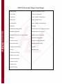
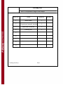
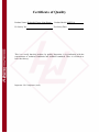
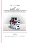
OPERATION MANUAL
Hydraulic Finger Joint Shaper
WINTER MX 3518
WARNING!
The operator must thoroughly read this manual before operation.
Keep this manual for future reference.
Henrik Winter Holztechnik GmbH
Druckereistr. 8
04159 Leipzig
Tel: +49 (0)341/ 4619021 Fax: +49 (0)341/4618358 Funk: +49 (0)171/2820443
Em@il: [email protected] Internet: www.winter-holztechnik.de
I. Purposes and Features
1. Main purposes: This machine is designed for use with a finger joint clamp. For
better utilization of lumber, particularly lumber of inferior quality, the machine
can finger joint and splice wood battens, and reduce waste of resource. Spliced
planking by finger joint features less deformation in consequential processing
and higher performance than ordinary planking.
2. Features: High level of automation and high spindle speed. The worktable
adopts a reliable hydraulic reciprocation. The processed finger joint ends are
more precise and smoother than those processed with manual or pneumatic
systems. The better finger joint quality helps improve productive efficiency and
save labors. The rails adopted are the most precise, stable and reliable straight
slide rails supplied by professional manufacturers. They are made of
high-hardness wear-proof steel and feature small deformation and wear
resistance.
This machine is compact, rational in structure and handsome in appearance. It
produces products of better quality than other equipment, and is an ideal choice
for wood furniture manufacturers.
II. Technical Parameters
No.
Parameters
Values
1
Available working area on worktable
490mm×600mm
2
Max. working width
400mm
3
Max. working height
120mm-180mm
4
Finger joint height
12mm-18mm
5
Saw blade diameter
300mm
6
Cutter bit diameter
160mm
7
Cylinder pressure
0.6-0.8Mpa
Memo.
50×1100
8
Hydraulic cylinder stroke
(heavy duty)
9
Max. operating pressure
70bar
10
Motor power rating
17.2kw
11
Spindle speed
7000r/min
12
Machine dimensions
(1710×1450×
1330)mm
Equivalent to
ISOVG 32-46
13
Hydraulic oil
petroleum base,
wear resistant
III. Schematic Diagram
IV. Main Structure
This machine is composed of the machine base, slide carriage, worktable, spindle,
high-power motor and cutting saw. The automatic reciprocation of the worktable
is achieved through the hydraulic system and electrical system.
1. The machine base is a welded steel structure of 6-20mm steel plate and bears
the static load of the machinery.
2. The finger joint shaper spindle is the heart and main structure of the machine
and is directly exposed to the cutting force. Therefore, superior quality raw
materials are used for such parts. The spindle is made of #45 steel, forged,
quenched and wrought to achieve excellent strength, rigidity, toughness and
resistance to deformation. Imported high-speed light-duty bearings (6208, 6011)
and high-quality high-speed lubricant are used. The front and rear glands adopt
a labyrinth-type sealing device. The spindle rotates at a speed above 7000r/min,
stable, high in machining precision, and generating no heat or vibration. The
elevation range is around 60mm.
3. Cutting saw. The motor is mounted level on the carriage of the dovetail groove
guide rail. The saw blade is directly installed on the flange of the motor axle.
The saw blade is 300mm in diameter.
4. Worktable and guide rail base. The worktable is made of cast iron and the guide
rail base is of ordinary 8-30mm steel plates, welded and quenched.
High-precision straight slide rails supplied by professional manufacturers are
adopted for worktable guide rails. Such products feature stable and reliable
performance, smooth, easy and accurate operation and resistance to twist, wear
and pressure, and are the most advanced guide rails available on the market.
High in cost and excellent in quality, the worktable adopts a hydraulic
reciprocation and the whole process is subject to the control of a full automatic
synchronous circuit for coordinated and synchronous operation. The crushing,
pressing and delivery of workpieces are accomplished through a pneumatic
device, synchronous to the hydraulic reciprocation.
5. Principles on hydraulic operation and electrical control. In the hydraulic device,
a 2.2kw-4 motor drives a bi-directional hydraulic pump to reciprocate
clockwise. For more information about the operation, refer to the usage and
operation of this machine. The hydraulic stroke and pressure are adjustable. The
electrical control is synchronous to the hydraulic operation. Refer to the
electrical control and the circuit diagram.
Bought-in Parts List
No.
Parts
Model
Quantity
Memo.
QUA63×200
1
Cylinder
QGA80×150
1 for each model
10Y-2SD40N150S
2
Bearing
6208
1 for each model
3
Bearing
6011
2 for each model
4
Flat belt
1
V. Installation and Debugging
The machine can be firmly placed on a concrete floor with all legs on the ground
and the machine surface in level. Rubber blocks can be placed on the parts
touching the ground to absorb vibration.
1. Adjustment of finger joint cutter bit
Clean the inner hole of the cutter and the cutter shaft. The cutter shall be
installed in such a manner that it rotates opposite to the feeding direction of the
workpiece. Press on the spacer and the copper sheathing (to prevent the locknut
from being removed), release the lock handle on the side, turn the elevation
handwheel till the lower edge of the cutter bit is a couple of millimeters below
the workpiece surface, lock again the side handle, and turn the cutter shaft with
hand to restore the belt to its normal position.
2. Adjustment of baffle plate and cutting saw
Adjust the distance between the baffle plate and the cutting saw blade (around
5mm), cut finger joint end of the workpiece, and adjust the distance between the
cutting saw blade and the cutter according to the workpiece. Generally speaking,
the end face the cutting saw produces shall allow a gap of 0.5mm after the finger
joints are manually connected. Lock the side handle after adjustment. If the front
end face of the cutting saw blade is too much higher above the teeth base of the
cutter, the length of the wrought finger joints will be insufficient, leaving too
much space in the middle after connection, and harming the strength of the
connected workpiece. If the front end face of the cutting saw blade is too much
lower below the teeth base of the cutter, the wrought finger joints will be too
long, leaving too much space at the side after connection, and harming the finger
joint strength of the workpiece.
3. Adjustment of Worktable Slide Carriage
When the machine has been used for some time, the slide carriage below the
worktable may get loose, affecting the finger joint quality. Loosen the fastening
bolt below the slide carriage, wrench tight the adjustment bolt on the side, and
lock the fastening bolt after adjustment.
4. Hydraulic Reciprocation of Worktable
Prior to work, the hydraulic pressure shall be adjusted according to the height
and depth of the workpiece to process. Start the hydraulic switch, the worktable
returns to reciprocation touching device, the suitable device on both end sides of
the guide rail base. The whole process shall be synchronous to the air pressure.
VI. Electrical Control System
This machine is highly automatic and the main operations are accomplished
through the electrical control system.
1. Prior to the use of this machine, the worker shall be familiar with the electrical
control system and the hydraulic principle, from the connection of the power
supply to the use of the electric buttons. The general operating steps are as
follows: make sure the mechanical, hydraulic and pneumatic systems are OK
and start in turn the cutter bit axle, cutting saw, pneumatic system and hydraulic
control system. The worktable brings the workpiece to reciprocate on the rail.
In case of emergency, cut the mains, turn off all stop buttons and close the
mains switch after the trouble is removed.
2. The worker must read the circuit diagram and the control box instructions
carefully.
VII. Usage
1. Prior to starting the machine, check whether the power is turned on, the
pneumatic and hydraulic systems are OK, and all the machine parts are locked,
and then, check whether the finger joint cutter bit and cutting saw blade are
securely clamped and the clamp nut and lock bolt are firmly pressed.
2. Oil the machine prior to start.
3. Prior to start, check the power supply and the electrical system, and check
whether the barometer and hydromanometer readings have attained the working
pressures. In case of under or over pressure, adjust according to the required
values. Check the pneumatic and hydraulic junction, connector, air and oil pipes
for leakage and check whether the valves are normal.
4. Adjust the height of the finger joint cutter bit and the spindle to the worktable
according to the working height of the workpiece. There is an elevation
adjustment bolt on the spindle case base. For adjustment, loosen the outer case
fastening bolt first, wrench the elevation adjustment bolt to the desired position,
and lock the same and the case base bolt.
5. Calibration of cutting saw blade. Generally speaking, the front extremity of the
cutting saw blade is 0.5mm behind the teeth base of the cutter, reducing the
force the cutter is exposed to.
6. Calibration of baffle plate. The surface of the baffle plate shall be 10mm behind
the front extremity of the cutting saw.
7. Place the planking (the finger joint side) against the baffle plate of the
worktable, turn on the pneumatic valve so that the top board of the cylinder
presses tight the workpiece (a bed piece can be used if the workpiece is too
thin). The workpiece shall be properly arranged. The side cylinder presses
vertically and the cylinder presses later. For the first operation of the machine,
pull the planking with hands to check whether the planking is firmly pressed.
8. Hydraulic and pneumatic adjustment. Prior to starting the machine, adjust the
synchronization of the hydraulic and pneumatic systems and coordinate the
working steps.
9. Process the workpiece now. The whole process is subject to the control of the
electrical control system. See the instructions on the operation of electric
buttons.
VIII. Safety Rules
1. Prior to using this machine, read the User Manual carefully and learn the
performance and usage.
2. This machine shall be properly grounded to avoid creepage.
3. To ensure normal operation of the machine, check machine parts for any
damages and replace the damaged parts immediately.
4. Prior to use, take away tools and wrenches.
5. To replace cutters, disconnect the power supply.
6. Keep the workplace clean and tidy. Untidiness may lead to accidents.
7. Workers on duty shall be properly dressed in coveralls.
8. The workplace is liable to accidents. Turn off the mains when the machine is
not in use.
9. Use suitable cutters only. Do not use parts unsuitable to the designed functions
of the machine.
10. To leave the machine, the worker shall wait till the machine completely stops.
11. Do not stand on the machine. Any touch of the cutter will result in serious
injuries.
12. The workpiece shall be fed opposite to the direction of the cutter revolution.
13. Clean and service the machine prior to and after use.
IX. Maintenance and Service
1. Clean the machine of rubbish and saw dust before checking off each day.
2. Oil the spindle sleeve with high-speed lubricant.
X. Attentions
1. When the machine is delivered, the worktable surface is covered with protective
paper and the power supply is set with overload protection.
2. Prior to using the machine, check whether the cutter bit is clamped and the
cutter blade clamp screw secured.
XI. Additional Instructions
As the Factory pursues the improvement of the product quality to meet the
customer’s requirements, it reserves the right to change the technical
specifications without notice.
Appendix: 3518 Circuit Diagram
SQ1: Worktable limit for moving forward
SQ2: Feeding limit
SQ3: Feeding return
SQ4: Worktable limit for moving backward
SQ5: Pressing cylinder releasing workpiece
YE1: Worktable moving forward
YE2: Worktable moving backward
MX3518 Hydraulic Finger Joint Shaper
Pressing rack
Cutter bit protective cover
Cutter body
Cutter bit clamp nut
Fixing pole
Cutter spindle clamp sleeve
Baffle plate
Cutter spindle motor
Pressing plate
Cutter spindle feeding flange
Worktable
Bushing
Worktable backing block
Spindle motor fine adjustment base
Worktable slide rail
Spindle motor fixing plate
Worktable hydraulic driving cylinder
Spindle motor belt pulley
Rail base
Spindle bearing gland
Elevation worm
Spindle bearing clamp nut
Worm wheel case
Spindle flat belt pulley
Elevation worm wheel
Spindle
End cap
Machine body
Elevation screw bolt
Spindle sleeve base
Elevation screw nut
Elevation carrier
Spindle sleeve
Spindle bearing
Packing List
MX3518 Hydraulic Finger Joint Shaper
Serial No.
Name
Quantity
1
Main frame
1
2
Operational manual instituti
1
3
Qualified certificate
1
4
Packing list
1
5
6
7
8
9
Packing check by:
Date:
Remark
Certificate of Quality
Product Name: Hydraulic Finger Joint Shaper
Ex-factory No.
Product Model: MX3518
Ex-factory Date:
This is to certify that this product, by quality inspection, is in conformity with the
requirements of technical conditions and technical standards. Thus it is allowed to
leave the factory.
Inspector: No.3 inspector (seal)