1
MDX-650A
MDX-650
MDX-500
PROGRAMMER'S MANUAL
NC code
Thank you very much for purchasing the product.
•
To ensure correct and safe usage with a full understanding of this product's performance,
please be sure to read through this manual completely and store it in a safe location.
•
Unauthorized copying or transferral, in whole or in part, of this manual is prohibited.
•
The contents of this operation manual and the specifications of this product are subject to
change without notice.
•
The operation manual and the product have been prepared and tested as much as possible.
If you find any misprint or error, please inform us.
•
Roland DG Corp. assumes no responsibility for any direct or indirect loss or damage
which may occur through use of this product, regardless of any failure to perform on the
part of this product.
•
Roland DG Corp. assumes no responsibility for any direct or indirect loss or damage
which may occur with respect to any article made using this product.
Part 1 Programming Basics
Table of Contents
Introduction ................................................................... 2
Part 1 Programming Basics
Programming ...................................................... 3
Coordinate Systems ............................................ 7
Setting Coordinate Values
(Amount of Movement) ......................... 10
Setting the Measurement Unit .......................... 11
Real-number Entry and Integer Entry .............. 11
Program Number .............................................. 12
Sequence Numbers ........................................... 12
Optional Block Skip ......................................... 12
Positioning (G00) ............................................. 13
Linear Interpolation (G01) ............................... 13
Circular Interpolation (G02 and G03) .............. 13
Cutter Compensation (G40, G41 and G42) ...... 15
Feed Rate .......................................................... 15
Spindle Motor Control (M03 and M05) ........... 16
Spindle Motor Speed ........................................ 16
Fixed Cycle ...................................................... 16
Program-related Errors ..................................... 16
Sample Program ............................................... 18
Part 2 Reference
[ Preparatory Functions (G Functions) ] ...................... 20
G00
Positioning ...................... 20
G01
Linear Interpolation ........ 21
G02 and G03
Circular Interpolation ..... 22
G04
Dwell .............................. 25
G10
Data Setting .................... 26
G17, G18 and G19 Plane ............................... 28
G20 and G21
Setting the
Measurement Unit ..... 28
G39
Corner-offset Circular
Interpolation .............. 29
Copyright © 2001 ROLAND DG CORPORATION
G40, G41 and G42 Cutter Compensation ...... 30
G50 and G51
Scaling ............................ 38
G54, G55, G56,
G57, G58 and G59 Selects
Coordinate System .... 39
G80, G81, G82, G83,
G85, G86 and G89 Fixed Cycle
(Canned Cycle) .......... 40
G90 and G91
Absolute and
Incremental ................ 44
G92
Coordinate System ......... 45
G98
Initial Level Return ........ 46
G99
Point R Level Return ...... 46
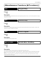
[ Miscellaneous Functions (M Functions) ] ................. 47
M00
Program Stop .................. 47
M01
Optional Stop ................. 47
M02
End of Program .............. 47
M03 and M05
Spindle Motor
Start/Stop ................... 47
M30
End of Program .............. 48
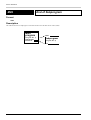
M98
Subprogram Call ............ 48
M99
End of Subprogram ........ 50
[ Spindle Speed Function (S Function) ] ..................... 51
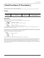
[ Feed Functions (F Functions) ] ................................. 53
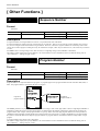
[ Other Functions ] ....................................................... 54
N
Sequence Number .......... 54
O
Program Number ............ 54
/
Optional Block Skip ....... 55
% or ER
Program Start ................. 55
EOB
End of Block .................. 56
()
Comment ........................ 56
Appendices
Words Table ...................................................... 57
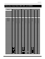
Character Code Table
(ISO, EIA, and ASCII) ................................ 59
http://www.rolanddg.com/
1
Part 1 Programming Basics
Introduction
What Is in This Manual
This manual explains those codes interpreted by numerical control machine tools (NC codes) which are supported by this machine.
Codes and functions which are not supported are not described.
This Manual Has Two Parts
“Part 1 — Programming Basics” describes such basic but necessary programming-related matters as programming, coordinate systems,
and how to set coordinate values (amount of movement).
“Part 2 — Reference” explains each of the codes in an encyclopedic form. Once a certain familiarity with programming has been
achieved, programming can be accomplished simply by glancing through this part.
2
Part 1 Programming Basics
Part
1
Programming Basics
Programming
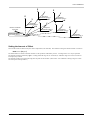
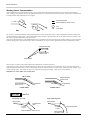
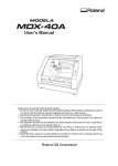
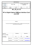
The Process of Programming
First, examine the drawing and determine such conditions as the workpiece material, the size of the workpiece to be prepared, the tool
diameter, the tool type, the proper turning speed, and the proper feed rate. Then determine the sequence in which to cut. The cutting
sequence is in extremely important point for carrying out cutting efficiently and safely.
In actual cutting, the moving portion may be either the workpiece or the spindle. Programming is carried out with consideration given to
how the tool moves, with no distinction made for the actual movement.
1
2
3
Workpiece material
Size of workpiece to be prepared
Tool diameter
Tool type
Turning speed
Feed rate
Cutting sequence
Etc.
G00X
G01X
G02X
Y
Y
Y
Drawing
Determine conditions and
cutting sequence
Process sheet
6
5
4
Cutting
Program
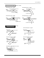
Once the appropriate conditions and cutting sequence for the job have been determined, then before cutting is begun, the programming
steps are written down on a piece of paper like the one shown below. (This form is called a “process sheet.”) This sheet is handy for
confirming the cutting sequence and numerical values.
N
N 01
N 02
N 03
N 04
N 05
N 06
N 07
N 08
N 09
N 10
N 11
•
G
X
Y
Z
A
S
F
M
%
G 90
G 00
Z ••••
X ••••
Y ••••
S 5000
G 01
F 300
M 03
Z ••••
A ••••
X ••••
G 02
X ••••
X ••••
Y ••••
Y ••••
Y ••••
F 150
3
Part 1 Programming Basics
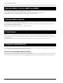
Program Structure
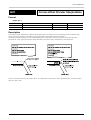
A program can be classified as a “main program” or a “subprogram.”
Main Program
Ordinarily, the machine operates according to instructions from a main program.
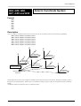
Subprogram
If a main program can be likened to the trunk of a tree, then subprograms are branches. When a main program specifies execution of a
subprogram of a certain number, the subprogram of that number is called up and executed.
Subprograms can be convenient when writing a program where the same task is to be performed a number of times. Program modularity
can also be promoted by creating subprograms which have good general utility.
A subprogram can call another subprogram.
Conceptual view of a main program and subprograms
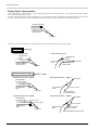
Program Structure and Format
Programming proceeds in accordance with the process sheet that has been prepared. The program is input using a dedicated input device
for NC codes, or with a general-purpose computer.
Input is made as shown in the figure below. Addresses such as G, M, X, I, and J are combined with numbers to specify the cutting steps
and tool movements.
* “%” for ISO or ASCII,
“ ER ” for EIA
(* For details on blocks, see “About Blocks,” which is the following section.)
4
Part 1 Programming Basics
%
: A block containing only a “%” must appear at the start of the data. This notifies the machine of the start of the data.
Such a block may optionally be present at the end of the data.
The character indicating the program start is “%” in the case of ISO or ASCII code, or “ ER ” in the case of EIA.
EOB
O
: The EOB (end of block) indicates the conclusion of the block. In ASCII, this is the LF (line feed) code.
: This inputs the program number. A program starts with a program number, and ends with either M02, M30, or M99.
M02 or M30 signifies the end of a main program, and M99 signals the end of a subprogram. Program numbers are
numerical values (integers). When four-digit numbers have been specified, you can enter program numbers from 0001
to 9999. When eight-digit numbers have been specified, you can enter numbers from 00000001 to 99999999. Be
careful to ensure that there are no duplicate program numbers or program numbers with different numbers of digits
within a single program.
Program numbers are used to call up subprograms.
N
: Sequence numbers are reference numbers for the program. They have absolutely no effect on the program (machine
operation).
G
: This is the preparatory function. The special functions are specified by the two-digit code following the “G.”
X(I)
Y(J)
: This indicates a coordinate value or movement distance. I, J, and K are used to specify the center coordinate of a
circle (or arc).
Z(K)
: For positive coordinates or movement directions, it is not necessary to prefix a “+” to the value.
A
: This indicates an angle or movement distance.
F
: This determines the feed rate.
S
: This determines the speed of the spindle motor.
M
: This is a miscellaneous function. It is used for such operations as starting and stopping the spindle motor.
M02
: This signals the end of the program. The spindle stops.
About Blocks
A program is a series of instructions (written commands) for the machine, expressed as symbols and numbers. The instructions are
separated by EOB markers, with the information between two EOB markers making up one instruction. This single instruction
between two EOB markers is called a “block.” Each block, in turn, is composed of “words.”
The types of words include those valid only within a block, those also valid outside of blocks until a word of the same group is specified,
those which activate a function immediately after being specified, those which activate a function at the end of the block in which they
are specified, and those which activate a function at the start of the block in which they are specified. Programming requires knowledge
of the characteristics of each word. See "APPENDICES-Words Table" or a chart of word characteristics.
<Examples of “words also valid outside of blocks until a word of the same group is specified”>
%
N01 G90
N02 G01X100Y100
Indicates that the specified coordinate value is absolute
(G90)
Linear interpolation from the current tool position to X = 100, Y = 100
(G01)
N03 Z-20
N04 G00Z20
Linear interpolation from the tool position moved to by N02 to Z = -20
N05 X0Y0
Movement (positioning) from the tool position moved to by N03 to X = 0, Y = 0.
Movement (positioning) from the tool position moved to by N03 to Z = 20 (G00)
5
Part 1 Programming Basics
Data Output from the Computer
Before outputting data, make the appropriate cable connections to link the computer and the machine. Refer to the user's manuals for
each model for explanations on making connections and connection specifications.
The character code systems supported by the machine are ASCII, ISO, and EIA. ASCII is an abbreviation for the “American Standard
Code for Information Interchange.” ASCII is the most widely used code standard established for computers to handle text, and is used by
virtually all computers. Text is output as normal ASCII unless you use software which can output ISO or EIA codes to the machine, or a
program which converts ASCII to ISO or EIA.
Numerically controlled machine tools (NC machines) generally use ISO (International Organization for Standardization) or EIA (Electronic Industry Association) as their character code system. Both of these use a data length of 8 bits, which means that ASCII, with a
length of 7 bits, cannot be used without modification. In an ISO code, the 8th bit is for parity checking, with bits 1 through 7 the same as
the corresponding ASCII code. (Refer to "Appendices Character Code Table (ISO, EIA, and ASCII)" .)
6
Part 1 Programming Basics
Coordinate Systems
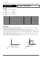
The machine uses the Cartesian coordinate system, which has three axes — the X axis, the Y axis, and the Z axis — each of which is
perpendicular to the other two.
When the optionally available rotary axis unit is installed, a rotation-axis coordinate system made up of an X axis, Z axis, and A axis is
added.
Y
+X
+Z
Z
+A
X
Machine Coordinate Systems
A machine coordinate system is a coordinate system determined mechanically. The origin point in a machine coordinate system is a
point specific to the machine, and cannot be moved. The origin point in a machine coordinate system is at the forward-left corner of the
machine's maximum range of operation, and is the point to which the machine moves at powerup.
Coordinate values (or amounts of movement) specified in an actual program are coordinates in a workpiece coordinate system.
Workpiece Coordinate Systems
A workpiece coordinate system is a coordinate system for workpiece machining. The origin point of a workpiece coordinate system is
the program's origin point according to an absolute specification.
There are two methods that can be used to set a workpiece coordinate system.
1. Setting using G92
2. Setting using G54 to G59
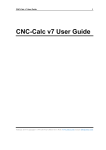
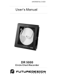
1. Setting a workpiece coordinate system using G92
A workpiece coordinate is defined by specifying the workpiece coordinate location of the current tool location.
For example, to set a point which is 20 mm (X), 15 mm (Y), 10 mm (Z) from the point to be taken as the origin of the present tool
location, the following should be set:
G92X20.0Y15.0Z10.0
Normally, the tool is moved to a point on the loaded workpiece and G92X0Y0Z0 (the workpiece coordinate origin point) is set.
Tool
Z
Y
Executing G92X20.0Y15.0Z10.0 10.0
sets the coordinate system taking
this as the origin point.
Z
15.0
Y
X
20.0
X
7
Part 1 Programming Basics
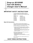
2. Setting a workpiece coordinate system using G54 to G59
This method is used to set up to six workpiece coordinate origin points and select a coordinate system from among these by means of the
program.
The workpiece coordinate systems 1 through 6 are set by specifying the amount of shift (the amount of workpiece origin point offset)
from the machine coordinate origin point to the workpiece coordinate origin point. Each workpiece coordinate system is set using the
machine's display. (Refer to the “User's Manual 3 Cutting Using NC-Codes” for information on making this setting.)
Z
Z
Y
Y
Workpiece
coordinate system 4
Z
Workpiece
coordinate system 3
X
Y
X
Z
Z
Y
Workpiece
coordinate system 1
Y
X
Z
Workpiece
coordinate system 2
Workpiece origin
point offset amount
Workpiece
coordinate system 6
X
Y
X
Workpiece
coordinate system 5
Machine coordinate
origin point
X
It is also possible to shift the six set workpiece coordinates by a desired distance at one time. Because the workpiece origin point is
offset, this is called EXOFS (external workpiece origin point offset amount). EXOFS is set with G10 or by using the machine's display.
(Refer to the “User's Manual 3 Cutting Using NC-Codes” for information on how to make the setting on the machine.)
Z
Z
Y
Y
Workpiece
coordinate system 4
Z
X
Y
X
Z
Workpiece
coordinate system 1
Z
Y
Y
X
Machine coordinate
origin point
Workpiece
coordinate system 2
X
External workpiece origin
point offset amount
EXOFS
8
Workpiece
coordinate system 3
Z
Workpiece
coordinate system 6
Y
X
Workpiece
coordinate system 5
X
Part 1 Programming Basics
G10 can be used to set not only the amount of shift for all workpiece coordinate systems, but also amounts of offset for each individual
workpiece coordinate system.
Z
Y
Workpiece
coordinate system 1
Z
X
Y
Amount of offset
by G10
Workpiece
coordinate system 1
Workpiece origin
point offset amount
X
Machine coordinate origin point
Selecting any of the workpiece coordinate systems from G54 to G59 and executing G92 causes the following to occur.
Y
Y
Y
Tool
Tool
G92X5.0Y5.0
executed at
this position
10.0
5.0
X
5.0
X
15.0
X
Amount of
offset by G92
Because G92 sets the current tool position to a desired coordinate value, the workpiece coordinate system selected at that time comes to
have a new origin point. The distance between the origin coordinate points before and after G92 is specified (that is, the amount of shift
of the coordinate system) is added to each workpiece origin point offset amount. This causes the workpiece coordinate systems from
G54 to G59 to be shifted by the same distance.
Z
Z
Y
Y
Workpiece
coordinate system 4
Z
X
Y
Amount of offset
by G92
X
Z
Workpiece
coordinate system 1
Z
Y
Y
X
Workpiece origin
point offset amount
Machine coordinate
origin point
Workpiece
coordinate system 3
Workpiece
coordinate system 2
X
Z
Workpiece
coordinate system 6
Y
X
Workpiece
coordinate system 5
X
9
Part 1 Programming Basics
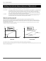
Setting Coordinate Values (Amount of Movement)
The addresses “X, Y, and Z” or “I, J, and K” are used, followed by the coordinate specification.
X, Y, Z, and A:
These specify coordinate values for positioning (G00), linear interpolation (G01), and the like. X, Y, and Z represent
the coordinates for the X, Y, and Z axes, respectively. It is not necessary to specify all three. As an example, if you
want to leave the Y and Z axes as they are, and shift only the X axis by 10 mm, “G00X10.0” should be input.
Also, A represents the angle of the rotation axis. For example, to rotate the rotation axis by 90 degrees,
use “A90.0.” Note that you cannot specify Y and A at the same time.
I, J, and K:
These specify the center point for circular interpolation (G02 and G03). I, J, and K represent the movement for the
X, Y, and Z axes from the current tool position, respectively. Another method of circular interpolation involves
specifying the radius. Refer to "G02 and G03 Circular Interpolation" for details.
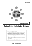
Absolute and Incremental
There are two types of coordinate specifications: absolute and incremental. These are toggled by G90 and G91.
The figure below shows the difference between absolute and incremental specifications on an X-Y plane. Absolute specifications
indicate the position as the distance from the workpiece coordinate origin, whereas incremental specifications indicate the amount of
movement from the current position.
Programming that specifies absolute coordinates is called “absolute programming,” and programming which specifies incremental
coordinates is termed “incremental programming.”
Y
Y
15
15
(19000, 12000)
(19000, 12000)
10
10
y=7000
(Increase in Y)
5
5
(4000, 5000)
0
5
10
15
Absolute
20
(mm)
X
0
(4000, 5000)
5
x=15000
(Increase in X)
10
15
20
(mm)
X
Incremental
The settings for G90 or G91 made on the machine remain in effect unless changed by programming.
There are no special rules for deciding when to use an absolute or incremental program. Examine the drawing and choose the one which
makes for the simplest program.
10
Part 1 Programming Basics
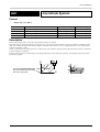
Setting the Measurement Unit
G20 and G21 can be used to set the measurement unit used for movement, feed rate, and offset amounts.
G20: Inch input
G21: Millimeter input
Either G20 or G21 is set at the start of the program, before setting the coordinate system. G20 and G21 should not be changed during
the course of a program. If the unit is not set by programming, the setting made on the machine is used.
The minimum units differ for inch input and millimeter input.
Minimum units
Inch input
0.0001 in.
Millimeter input
0.001 mm
Movement
Feed rate
Offset amounts
Command
G20
G21
G00X10.0
10 in.
10 mm
G00X10000
1 in.
10 mm
F60.0
60 inch/min.
60 mm/min.
F45000
4.5 inch/min.
45 mm/min.
G10P01R10.0
10 in.
10 mm
G10P01R10000
1 in.
10 mm
Real-number Entry and Integer Entry
Movement amount (length), feed rate, and time may be input using either real-number entry or integer entry.
Input of a number which contains a decimal point (for example “10.0” or “10.”) is called real-number entry, and input of a number
without a decimal point is called integer entry. A value such as “10.0” where the portion to the right of the decimal point is zero may be
abbreviated to “10.” with no change in value.
When real-number entry is used, the numerical value is interpreted as being in the measurement unit that has been set. When integer
entry is used, the numerical value is interpreted as being the minimum unit of the measurement unit that has been set. Some examples of
this are as follows.
Amount of
X10.0
movement (length) X1000
10 mm or 10 in.*
1 mm or 0.1 in.*
Feed rate
F60.0
F120000
60 mm/min. or 60 inch/min.*
120 mm/min. or 12 inch/min.*
Time
G04X10.0
G04X1000
10 sec. dwell
10 sec. dwell
Angle
A180.0
A1800
180°
1.8°
* The measurement unit is set by G20 (inch input) or G21 (millimeter input).
* If the unit is not set by programming, the setting made on the machine is used.
There are two types of methods for setting the speed of the spindle motor: setting as an rpm value, and setting as a numerical code. See
"Spindle Speed Function (S Function) for details.
11
Part 1 Programming Basics
Program Number
A main program or subprogram calls and executes another program by specifying a program number. The program number appears at
the start of the program.
To specify a program number, enter “O” (the letter “oh”) followed by the four- or eight-digit integer value for the program number. The
range for program numbers is from 0001 to 9999 when four-digit numbers have been specified, or from 00000001 to 99999999 when
eight-digit numbers have been specified. You cannot enter “0” (zero) for a program number.
The number of digits employed to specify numbers is set on the machine. For more information on how to make the setting, refer to
“User’s Manual 3 — Cutting Using NC Codes.”
The section that extends from the place where the program number is input to an M02, M30, or M99 is recognized as one program (or
subprogram). M02 or M30 is used to indicate the end of a main program, and M99 is used to signal the end of a subprogram.
Sequence Numbers
A sequence number is an integer number for a block. It is specified at the start of the block.
A sequence number may either be present or absent from any or all blocks. There is also no need for sequence numbers to be consecutive, or to be arranged in order from smaller to larger numbers. However, consecutive sequence numbers are customarily used to mark
critical places within a program.
Enter “N,” followed by the four- or eight-digit integer value for the sequence number. The range for sequence numbers is from 0001 to
9999 when four-digit numbers have been specified, or from 00000001 to 99999999 when eight-digit numbers have been specified.
A sequence number cannot be substituted for a program number.
The number of digits employed to specify numbers is set on the machine. For more information on how to make the setting, refer to
“User’s Manual 3 — Cutting Using NC Codes.”
Optional Block Skip
This function makes it possible to skip over a desired block within a program. Optional block skip is specified at the start of the
program.
Enter a "/" (slash) at the start of the block.
The setting for enabling or disabling block skip is made on the machine. (Refer to "User's Manual 3 -- Cutting Using NC Codes.")
12
Part 1 Programming Basics
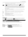
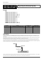
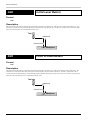
Positioning (G00)
This moves in a straight line at maximum speed from the current tool position to the specified point. The word for positioning is
“G00.” The addresses X, Y, and Z are used to specify the destination point. When X, Y, and Z are all specified, the three axes move
simultaneously.
If the tool path is blocked by the workpiece or another object during movement, it is necessary to take steps to prevent the tool from
striking the object, and one way to do this is to move each axis one at a time. An example of this would be to use the absolute specification “G00Z5000” to raise the tool, followed by “G00X1000Y1000” for horizontal movement.
X
* When the coordinates are absolute
X
* When the coordinates are absolute
Linear Interpolation (G01)
This cuts in a straight line from the current position to the specified point. The word for linear interpolation is “G01.” The addresses X,
Y, and Z are used to specify the destination point. When X, Y, and Z are all specified, the three axes move simultaneously.
G01 does not include the function for starting the spindle motor. This means that if the spindle motor is not already turning, the M03
word must be given beforehand to start it.
In actual cutting, compensation for the tool diameter is required. Refer " G40, G41 and G42 Cutter Compensation" for more information on compensation of the tool diameter.
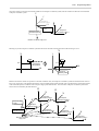
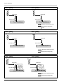
Circular Interpolation (G02 and G03)
This cuts a circular shape from the current position to the specified point. The words for circular interpolation are “G02” and “G03.”
Any address of the set X, Y, and Z is used to specify the destination coordinates, and any address of the set I, J, and K is used to specify
the center of the circle. I, J, and K always specify the movement distance (incremental value) to the center point of the circle or arc,
with no regard for G90 or G91.
G02 and G03 do not include the function for starting the spindle motor. This means that if the spindle motor is not already turning, the
M03 word must be given beforehand to start it.
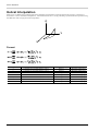
G02 and G03 interpolate in different directions — clockwise for G02 and counterclockwise for G03.
Circular interpolation can be carried out on any of the two-dimensional planes — the X-Y plane, the Z-X plane, or the Y-Z plane. The
desired plane is specified with G17 (X-Y plane), G18 (Z-X plane), or G19 (Y-Z plane). See "G17, G18 and G19 Plane" for the
details of plane specification.
13
Part 1 Programming Basics
Z
+Z
G02
G03
G02
+Y
Y
G02
G03
G03
Clockwise
Counterclockwise
+X
X
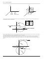
Even when the point for the destination and the center of the circle are identical, circular interpolation is carried out as shown below
according to the direction of interpolation.
Y
G02
G03
Clockwise
rotation
Counter
clockwise
rotation
(7000, 17000)
G17G02X7000Y17000I12000J5000
(12000, 5000)
G17G03X7000Y17000I12000J5000
X
(0, 0)
There is another method, which involves specifying the radius of the circle instead of specifying the circle’s center point. This method is
convenient because numerical values read from the drawing can be used directly.
Two circles with identical radii and passing through two points exist. This means that if the interpolation direction, radius of the circle,
and point for the destination of interpolation have been specified, there are two circles. These two circles can be differentiated by
specifying a positive value for the radius if the center angle is 180 degrees or less, and a negative radius if the center angle exceeds 180
degrees.
Y
G17G02X17000Y-7000R-13000
R1
30
00
A(0, 0)
X
G17G02X17000Y-7000R13000
B(17000, -7000)
0
00
13
R
14
Part 1 Programming Basics
Cutter Compensation (G40, G41 and G42)
The movement of the tool specified by the program is the path taken by the center of the tool. Because the tool has a certain thickness
(i.e., a certain diameter), it will over-cut by an amount equal to its radius if the coordinates on the drawing are input just as they are.
To cut a shape as specified by the drawing, the tool must be made to move at a place which shifted away by a distance equal to the tool
radius. This is called the “tool-diameter offset.”
Using this function makes it possible to input the values from the drawing as coordinate values (or amounts of movement) with no need
for modification, thus facilitating programming. Also, if cutting is to be performed with a tool that has a different tool diameter, it is
only necessary to change the amount of offset.
The words for cutter compensation are “G40,” “G41,” and “G42.”
G40: Cancel cutter compensation
G41: Cutter compensation -- left
G42: Cutter compensation -- right
15
R1
5
R15
15
R15R
45
25
Workpiece
R
5+
R1
R15
15
R1
5
25
R
15
Tool
45
: Tool path
Feed Rate
This determines the feed rate for the workpiece and the spindle. The F function is used to make the setting.
The feed rate generally varies according to the cutting parameters (such as the spindle speed, tool diameter, and workpiece material).
The F function is activated at the start of the block in which it is specified.
The feed rate is specified as a real or integer value following the “F.”
F100.0
Feed rate set at 100 mm/min. (when millimeter input is used)
F100000
Feed rate set at 100 mm/min. (when millimeter input is used)
Feed Rate Override
"Feed rate override" refers to manually changing the feed rate specified by the program. This is mainly used to adjust the feed rate during
cutting. This function may or may not be supported, depending on the machine. Refer to the "User's Manual 3 -- Cutting Using NC-Codes"
and see "1 SPEED OVER RIDE" of "Description of the Display Menus" for information on how to make this setting.
15
Part 1 Programming Basics
Spindle Motor Control (M03 and M05)
These turn the spindle motor on or off. The M function is used for this.
M03 and M05 are used to control the spindle motor. M03 starts rotation of the spindle, and M05 stops it.
These functions are activated at the end of the block in which they are specified together.
Spindle Motor Speed
The S function is used to set the speed for the spindle motor.
The S function does not include the function for starting the spindle motor. It functions only when the spindle has been started with
M03, or when the spindle is already turning.
This function is activated at the end of the block in which it is specified.
Fixed Cycle
The fixed cycle (or canned cycle) is a command for executing a series of pre-established operations for cutting, such as drilling.
This command can execute several blocks of cutting operations in a single block, thereby simplifying programming. This also reduces
the amount of data.
See "Fixed Cycle (Canned Cycle) G80, G81, G82, G85, G86 and G89" for details of the specifications for the fixed cycle.
Program-related Errors
An error is generated when an unsuitable value has been set for a parameter, or when the machine cannot interpret the program. Only
error messages related to programming are described in this manual.
Errors Occurring During Program Execution
When an error occurs, operation pauses and an error message is displayed.
The cutting operation can be continued as-is after an error has been displayed, but this is not recommended because operation following
the occurrence of an error may not be correct. Instead, stop program execution and correct the place where the error was generated.
16
Part 1 Programming Basics
Error message
Description
Bad Parameter
The value of a parameter exceeds the allowable range, or the value of the radius for circular
interpolation or the amount of offset is not correct.
Address Undefined
Only a parameter has been set. The code which specifies the parameter has not been set.
Parameter Undefined
A parameter has not been set.
Code Cannot Execute
This is displayed when an attempt was made to execute an unrecognizable command, when
cutter compensation was started while in the circular interpolation mode, or when an attempt was
made to execute a command which cannot be used during tool-diameter or tool-length compensation.
Program Number
Not found
The program number specified by M98 could not be found.
Sub-Program
Nest Over
An attempt was made to call a fifth-level subprogram from a fourth-level subprogram of a main
program.
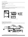
Display Operations When an Error Occurs During Program Execution
Error display
Bad Parameter
Press the [EXIT] key.
Pause display
PAUSE>CONTINUE
STOP
Turn the dial to move
the arrow to [STOP],
then press the [ENTER] key.
Turn the dial to move
the arrow to [CONTINUE],
then press the [ENTER] key.
Program execution
is stopped
All commands in the block
containing the error are
ignored, and operation is
resumed with the next block
Error While Registering Cutting Data
In the following cases, the display is made when program integrity is analyzed after registering the subprograms.
At such times, the message appears for two or three seconds, then reverts to the original screen. Correct the program, then send it again.
Error message
Description
Sub-Program
Regist Error
There are more than ten subprograms. The maximum number of subprograms that can be
specified in one set of data is ten.
After correcting the program, resend the data.
Duplicate
Sub-Program Number
The program contains multiple subprograms with the same program number. The same program
number may not be set for more than one subprogram within a single set of data.
After correcting the program, resend the data.
17
Part 1 Programming Basics
Sample Program
45
15
R
15
R15
15
35
Workpiece
20
Y
: Tool path
R
: 3 mm tool radius
R
8 mm
60
8 mm
X
Tool
Tool position
at start
%
Data start
O0001
N01 G91
Program number
Incremental programming
N02 G21
N03 G92X0Y0Z0
Set millimeter input
Set workpiece coordinate origin point
N04 G10P01R3.0
N05 G00Z5.0
Set 3 mm of offset for offset number 1
Move tool to position of 5 mm on Z axis (X0Y0 unchanged)
N07 F300.0S6000M03
N06 G17G41D01G00X8.0Y8.0
Set motor speed to 6,000 rpm and feed rate to 300 mm/min., and rotate spindle
Start cutter compensation and move tool to X-axis 8 mm and Y-axis 8 mm
N08 G01Z-7.0
N09 G01Y35.0
Linear interpolation to -7 mm on Z axis
Linear interpolation to 35 mm on Y axis
N10 X45.0
N11 G03X15.0Y-15.0I15.0
Linear interpolation to 45 mm on X axis
Circular interpolation (counterclockwise) to position X 15 mm Y -15 mm from current tool position
N12 G01Y-20.0
N13 X-60.0
Linear interpolation to -20 mm on Y axis
Linear interpolation to -60 mm on X axis
N14 Z7.0
N15 G40G00X-8.0Y-8.0
Linear interpolation to 7 mm on Z axis
Cancel cutter compensation and return to start point
N16 M05
M02
Main spindle rotation halt
Program end
%
Data end
* The example program shown above is for when using ISO or ASCII as the code.
18
Part 2 Reference
2
Part
Reference
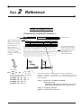
How to Read Part 2
[ Preparatory Functions (G Functions) ]
Word
Words in square brackets
(“[]”) may be omitted.
Parameters are given in
italics (such as “x,” “y,”
and “feed rate”).
The words enclosed in
curly brackets (“{}”) are
a range of available
selections. Any one may
be chosen.
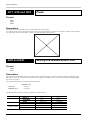
Word function
Positioning
G00
Format
G00[X
x][Y y][Z z]
Parameter
Function
Acceptable range
Effective range
x
Coordinate or movement distance (X axis)
Range 1
Maximum cutting range
y
Coordinate or movement distance (Y axis)
Range 1
Maximum cutting range
z
Coordinate or movement distance (Z axis)
Range 1
Maximum cutting range
Description
This effects movement in a straight line and at maximum speed from the current tool position to the specified coordinate point. When
incremental programming is used, the tool moves the specified movement distance. G00 ignores any set feed rate, and always effects
movement at maximum speed. When “MOVE OVER RIDE” has been set on the machine, however, operation is according to this
setting.
The destination’s coordinates (or movement distances) are specified with addresses X, Y, and Z. It is not necessary to specify values for
every one of these addresses. As an example, if only the X axis is specified (e.g., G00X100), the tool moves only along the X axis, with
no movement on the Y or Z axes. This is also the case when only the Y axis, Z axis, X and Y axes, Y and Z axes, or Z and Y axes are
specified. When addresses X, Y, and Z are all specified, the tool moves along all three axes simultaneously.
G00 is also effective outside the block until a word of the same type is encountered. If XxYyZz is specified in the block after specifying
G00, with no G01, G02, or G03, linear movement to the specified coordinate is effected.
If the tool path is blocked by the workpiece or another object during movement, it is necessary to take steps to prevent the tool from
striking the object, and one way to do this is to move each axis one at a time.
X
* When the coordinates are absolute
This is an explanation of
the functions of the word
and its parameters, along
with cautions or other
important points to
observe when using.
X
* When the coordinates are absolute
For example,
G17
{
G02
G03
}
[X x ][Y y ]
{
[I cx ][J cy ]
R radius
uses this shorthand form to indicate the
following four expressions:
G17G02[X x ][Y y ][I cx ][J cy ]
G17G03[X x ][Y y ][I cx ][J cy ]
G17G02[X x ][Y y ] R radius
G17G03[X x ][Y y ] R radius
}
The range and functions of a parameter are shown in table form.
“Range 1” , “Range 2” and “Range 3” are shorthand expressions for
ranges in which an error does not occur. These correspond to the
following ranges.
Range 1: Integer entry: -8388608 to 8388608
Real-number entry:
-8388.608 to 8388.608 (when millimeter input is used)
-838.8608 to 838.8608 (when inch input is used)
Range 2: -8388608 to 8388608
Range 3: -134217728 to 134217728
19
Part 2 Reference
[ Preparatory Functions (G Functions) ]
G00
Positioning
Format
G00[X x ][Y y ][Z z ][A a ]
Parameter
Acceptable range
Effective range
x
y
Coordinate or movement distance (X axis)
Coordinate or movement distance (Y axis)
Function
Range 1
Range 1
Maximum cutting range
Maximum cutting range
z
a
Coordinate or movement distance (Z axis)
Angle or movement distance (A axis)
Range 1
Range 1
Maximum cutting range
Maximum cutting range
Description
This effects movement in a straight line and at maximum speed from the current tool position to the specified coordinate point. When
incremental programming is used, the tool moves the specified movement distance. G00 ignores any set feed rate, and always effects
movement at maximum speed. When “MOVE OVER RIDE” has been set on the machine, however, operation is according to this
setting.
The destination’s coordinates (or movement distances) are specified with addresses X, Y, and Z. It is not necessary to specify values for
every one of these addresses. As an example, if only the X axis is specified (e.g., G00X100), the tool moves only along the X axis, with
no movement on the Y or Z axes. This is also the case when only the Y axis, Z axis, X and Y axes, Y and Z axes, or Z and Y axes are
specified. When addresses X, Y, and Z are all specified, the tool moves along all three axes simultaneously.
G00 is also effective outside the block until a word of the same group is encountered. If X x Y y Z z is specified in the block after
specifying G00, with no G01, G02, or G03, linear movement to the specified point is effected.
If the tool path is blocked by the workpiece or another object during movement, it is necessary to take steps to prevent the tool from
striking the object, and one way to do this is to move each axis one at a time.
Y y and A a cannot be specified at the same time. Specifying the Y axis and the A axis within the same block results in an error.
X
* When the coordinates are absolute
20
X
* When the coordinates are absolute
Part 2 Reference
G01
Linear Interpolation
Format
G01[X x ][Y y ][Z z ][A a ]
Parameter
x
Function
Coordinate or movement distance (X axis)
Acceptable range
Range 1
Effective range
Maximum cutting range
y
z
Coordinate or movement distance (Y axis)
Coordinate or movement distance (Z axis)
Range 1
Range 1
Maximum cutting range
Maximum cutting range
a
Angle or movement distance (A axis)
Range 1
Maximum cutting range
Description
This effects linear cutting from the current tool position to the specified coordinate. When incremental programming is used, cutting for
the specified movement distance is performed.
Cutting is performed at the spindle speed and feed rate that have been specified. Refer to "Feed Function (F Function)" for an explanation of the feed rate and to "Spindle Speed Function (S Function)" for a description of spindle speed.
The destination’s coordinates (or movement distances) are specified with addresses X, Y, and Z. It is not necessary to specify values for
every one of these addresses. As an example, if only the X axis is specified (e.g., G01X100), the tool moves only along the X axis, with
no movement on the Y or Z axes. This is also the case when only the Y axis, Z axis, X and Y axes, Y and Z axes, or Z and Y axes are
specified. When addresses X, Y, and Z are all specified, the tool moves along all three axes simultaneously.
G01 is also effective outside the block until a word of the same group is encountered. If X x Y y Z z is specified in the block after
specifying G01, with no G00, G02, or G03, linear interpolation to the specified point is effected. This makes it possible to carry out
continuous linear interpolation.
G01 does not include the function for starting the spindle motor. If the spindle motor is not already turning, the M03 word should be
given beforehand to start it.
The specified tool movement is the path followed by the center of the tool. Programming should be done so that the tool passes over a
path which is offset by a distance equal to the radius of the tool.
Y y and A a cannot be specified at the same time. Specifying the Y axis and the A axis within the same block results in an error.
21
Part 2 Reference
G02 and G03
Circular Interpolation
Format
G17
{
G02
G03
}
[X x ][Y y ]
{
[I cx ][J cy ]
R radius
}
G18
{
G02
G03
}
[X x ][Z z ]
{
[I cx ][K cz ]
R radius
}
G19
{
G02
G03
}
[Y y ][Z z ]
{
[J cy ][K cz ]
R radius
}
Parameter
Acceptable range
Effective range
x
y
Coordinate or movement distance (X axis)
Coordinate or movement distance (Y axis)
Function
Range 1
Range 1
Maximum cutting range
Maximum cutting range
z
cx
Coordinate or movement distance (Z axis)
Movement distance to circle (arc) center (X axis)
Range 1
Range 1
Maximum cutting range
Maximum cutting range
cy
cz
Movement distance to circle (arc) center (Y axis)
Movement distance to circle (arc) center (Z axis)
Range 1
Range 1
Maximum cutting range
Maximum cutting range
radius
radius
Range 3
Maximum cutting range
Description
This cuts an arc at the specified feed rate and spindle speed from the current tool position to the specified point. Circular interpolation
can be carried out only on the X-Y plane, Z-X plane, or Y-Z plane.
The specification for the two-dimensional plane is made with G17, G18, or G19. These specify the X-Y plane, Z-X plane, and Y-Z
plane, respectively. The specification for the X-Y plane is enabled when the machine’s power is switched on.
To specify the destination point for interpolation, use is made of addresses X and Y for G17, X and Z for G18, and Y and Z for G19.
The center point for the arc is specified with addresses I and J for G17, I and K for G18, and J and K for G19. I, J, and K always specify
the movement distance (incremental value) to the center point of the circle or arc, with no regard for G90 or G91. It is also possible to
specify the radius R for the arc instead of using I, J, or K.
When the point of the current tool position is specified as the destination for interpolation, a circle with a center angle of 360° is cut.
G02 and G03 differ in the direction of interpolation for the arc (i.e., the direction of tool movement). G02 performs clockwise circular
interpolation, whereas G03 performs counterclockwise interpolation.
Z
+Z
G02
G03
G02
Y
G02
+Y
G03
G03
Clockwise
+X
22
Counterclockwise
X
Part 2 Reference
Even when the point for the destination and the center of the circle are identical, circular interpolation is carried out as shown below
according to the direction of interpolation.
Y
G02
G03
Clockwise
rotation
Counter
clockwise
rotation
(7000, 17000)
G17G02X7000Y17000I12000J5000
(12000, 5000)
G17G03X7000Y17000I12000J5000
X
(0, 0)
Two circles with identical radii and passing through two points exist. This means that if the interpolation direction, radius of the circle,
and point for the destination of interpolation have been specified, there are two circles. These circles can be differentiated by specifying
a positive value for the radius if the center angle is 180 degrees or less, and a negative radius if the center angle exceeds 180 degrees.
Y
G17G02X17000Y-7000R-13000
R1
30
00
A(0, 0)
X
G17G02X17000Y-7000R13000
B(17000, -7000)
0
00
13
R
G02 and G03 are also effective outside the block until a word of the same group (G00, G01, G02, or G03) is encountered. G17, G18,
G19 also remain effective even outside the block until a word of the same group (G17, G18, or G19) is specified.
G02 and G03 do not include the function for starting the spindle motor. This means that if the spindle motor is not already turning, the
M03 word must be given beforehand to start it.
The specified tool movement is the path followed by the center of the tool. Please make calculations to have the tool pass through a
location that is offset by a distance equal to its radius, and then carry out the programming accordingly. An error is generated when an
attempt is made to execute a code for starting cutter compensation (G41 or G42) while in the circular interpolation mode.
23
Part 2 Reference
Helical Interpolation
When an axis is added to the coordinate point for the destination of interpolation, movement in the form of a helix is carried out, as
shown below. This is called helical interpolation. A three-dimensional curve is cut by performing a synchronized linear operation along
the added axis while carrying out circular interpolation.
Z
Y
X
Format
Parameter
24
Function
Acceptable range
Effective range
x
y
Coordinate or movement distance (X axis)
Coordinate or movement distance (Y axis)
Range 1
Range 1
Maximum cutting range
Maximum cutting range
z
cx
Coordinate or movement distance (Z axis)
Movement distance to circle (arc) center (X axis)
Range 1
Range 1
Maximum cutting range
Maximum cutting range
cy
cz
Movement distance to circle (arc) center (Y axis)
Movement distance to circle (arc) center (Z axis)
Range 1
Range 1
Maximum cutting range
Maximum cutting range
radius
radius
Range 3
Maximum cutting range
Part 2 Reference
G04
Dwell
Format
G04[X time(X) ]
G04[P time(P) ]
Parameter
Function
Acceptable range
time(X)
Dwell time
Range 1
time(P)
Dwell time
Range 2
Effective range
0 to 3600000 [ msec.]
or 0 to 3600.000 [ sec.]
0 to 3600000 [ msec.]
Description
G04 specifies the time interval for moving from the previous block to the next block. G04 is normally specified as a single block all by
itself.
G04 is used with the aim of cutting a precise angle, ensuring precision when cutting the bottom of a drilled hole, or the like.
The desired dwell time is specified after X or P. Either X or P may be used, but P must be specified with an integer. The specified time is
in seconds when a real number is used, and in milliseconds when an integer is used.
G04X10.0
10-second dwell
G04X10000
10-second dwell (in millisecond units)
G04P10000
10-second dwell (in millisecond units)
25
Part 2 Reference
G10
Data Setting
Format
G10L2P coordinate [X x][Y y][Z z][A a]
G10[P number ][R offset ]
Parameter
coordinate
Function
Work coordinate
Acceptable range
Range 2
Effective range
0 to 6
x
y
Coordinate or movement distance (X axis)
Coordinate or movement distance (Y axis)
Range 1
Range 1
Maximum cutting range
Maximum cutting range
z
number
Coordinate or movement distance (Z axis)
Offset number
Range 1
Range 2
Maximum cutting range
1 to 3
offset
a
Amount of offset
Angle or movement distance (A axis)
0 to 10 [mm]
or 0 to 0.39 inch
0 to 10 [mm]
or 0 to 0.39 inch
Range 1
Maximum cutting range
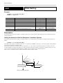
Description
This sets the amount of shift for workpiece coordinate systems as well as the amount of offset used by the cutter compensation and toollength compensation.
Setting the Amount of Shift for Workpiece Coordinate Systems
This sets the amount of shift for workpiece coordinate systems 1 to 6 of G54 and G59. The format for setting the amount of shift is as
follows.
G10L2P coordinate [X x][Y y][Z z][A a]
The number of the workpiece coordinate system (1 to 6) is specified by coordinate. Specifying “0” causes the amount of shift (EXOFS)
to be set for all workpiece coordinate systems.
The amounts of shift for the coordinate system are specified by x, y, z and a. When “0” has been specified for coordinate, the value is
set with the machine coordinate origin taken as 0. When coordinate specifies the number of a workpiece coordinate system (1 to 6), the
value is set with a point shifted from the machine coordinate origin by a distance equal to EXOFS taken as 0.
Refer to "Part1_Coordinate Systems" for detailed information about coordinate systems.
Z
Y
Workpiece
coordinate system 1
X
Amount of offset
by G10
Workpiece origin
point offset amount
Machine coordinate origin point
26
Z
Y
Workpiece
coordinate system 1
X
Part 2 Reference
Z
Z
Y
Y
Workpiece
coordinate system 4
Z
X
Y
X
Z
Workpiece
coordinate system 1
Z
Y
Y
X
Machine coordinate
origin point
Workpiece
coordinate system 2
X
External workpiece origin
point offset amount
EXOFS
Workpiece
coordinate system 3
Z
Workpiece
coordinate system 6
Y
X
Workpiece
coordinate system 5
X
Setting the Amount of Offset
This sets the amount of offset used by the cutter compensation (G41 and G42). The format for setting the amount of offset is as follows.
G10P number [R offset ]
The offset number for which an amount of offset is to be specified is indicated by number. An integer from 1 to 3 may be specified.
The amount of offset is indicated by offset. A setting within the range of 0 to 10.00 mm (or within the range of 0 inch to 0.39 inch for
inch input) may be made.
The amount of offset can be specified using the LCD panel on the machine. (Refer to the “User's Manual 3 Cutting Using NC-Codes”
for a description of the procedure.)
27
Part 2 Reference
G17, G18 and G19
Plane
Format
G17
G18
G19
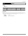
Description
This specifies a two-dimensional plane for circular interpolation (G02 or G03).
G17 specifies the X-Y plane, G18 specifies the Z-X plane, and G19 specifies the Y-Z plane. Each of these is normally used in combination with G02 or G03 in the same block. (Refer to "Circular Interpolation G02 and G03").
G20 and G21
Setting the Measurement Unit
Format
G20
G21
Description
This sets the measurement unit used for movement, feed rate, and offset amounts. G20 sets inch input, and G21 sets millimeter input.
Either G20 or G21 is set at the start of the program, before setting the coordinate system. G20 and G21 should not be changed during
the course of a program.
The minimum units differ for inch input and millimeter input.
Minimum units
Inch input
Millimeter input
0.0001 in.
0.001 mm
Changing the measurement unit results in interpretation as shown below.
Command
28
G20
G21
Movement
G00X1.0
G00X1000
1 in.
0.1 in.
1 mm
1 mm
Feed rate
F60.0
F45000
60 inch/min.
4.5 inch/min.
60 mm/min.
45 mm/min.
Offset amounts
G10P01R10.0
G10P01R10000
10 in.
1 in.
10 mm
10 mm
Part 2 Reference
G39
Corner-offset Circular Interpolation
Format
G39[X x][Y y]
Parameter
x
y
Function
Coordinate or movement distance (X axis)
Acceptable range
Range 1
Effective range
Maximum cutting range
Coordinate or movement distance (Y axis)
Range 1
Maximum cutting range
Description
Corner-offset circular interpolation is a function which performs tool movement at crossover points during cutter compensation by
means of circular interpolation. The radius of circular interpolation is the amount of offset (tool radius).
Corner-offset circular interpolation can be executed during cutter compensation, when G41 or G42 has already been executed.
The values for x and y specify the direction of movement after corner-offset circular interpolation has been performed.
G39 is a word which is effective only within a block. Arc interpolation is used only for corners specified as G39. G39 does not affect
G00, G01, G02, or G03.
29
Part 2 Reference
G40, G41 and G42
Cutter Compensation
Format
{
G00
G01
G17
{
}
G40[X x ][Y y ]
G00
G01
}{
G41
G42
} D number
Parameter
x
[X x ][Y y ]
Function
Coordinate or movement distance (X axis)
y
number
Coordinate or movement distance (Y axis)
Offset number
Acceptable range
Range 1
Range 1
0 to 3
Effective range
Maximum cutting range
Maximum cutting range
0 to 3
Description
The movement of the tool specified by the program is the path taken by the center of the tool. Because the tool has a certain thickness
(i.e., a certain diameter), it will over-cut by an amount equal to its radius if the coordinates on the drawing are input just as they are.
To cut a shape as specified by the drawing, the tool must be made to move at a place which shifted away by a distance equal to the tool
radius. This is called the “tool-diameter offset.”
Using this function makes it possible to input the values from the drawing as coordinate values (or amounts of movement) with no need
for modification, thus facilitating programming. Also, if cutting is to be performed with a tool that has a different tool diameter, it is
only necessary to change the amount of offset.
The words for cutter compensation are “G40,” “G41,” and “G42.”
G40: Cancel cutter compensation
G41: Cutter compensation -- left
G42: Cutter compensation -- right
15
R
15
R15
15
R15R
45
25
Workpiece
R
5+
R1
R15
15
R
15
25
R
15
Tool
45
: Tool path
Restrictions on Cutter Compensation
Cutter compensation is subject to the following restrictions.
1. Cutter compensation can be performed only in the XY plane.
2. Do not position two or more blocks without X- and Y-axis motion commands next to each other during tool diameter compensation.
It may cause excessive or insufficient cutting depth.
3. No interference check for cutter compensation is performed. However, an error is generated if an attempt is made to machine the
inner side of a circle or arc with an amount of offset that is larger than the radius for circular interpolation.
30
Part 2 Reference
4. When circular interpolation has been specified, an error is generated if cutter compensation is started or canceled. When positioning
(G00) or linear interpolation (G01) has been specified, cutter compensation should be started or canceled.
5. When cutter compensation for circular interpolation is performed, parameters cannot be changed using the display with operation
paused.
6. When fixed-cycle operation has been specified, executing or canceling cutter compensation causes an error to be generated.
7. Performing any of the following operations or settings during cutter compensation causes an error to be generated.
Changing the offset number
: To change the offset number, first cancel cutter compensation. Then execute G41 or G42
again, and change the offset number.
Switching the direction of compensation : When G41 (cutter compensation -- left) has been used, executing G42 causes an error to be
generated. Similarly, when G42 (cutter compensation -- right) has been used, executing
G41 causes an error to be generated.
Specifying a plane
: Executing G17, G18, or G19 causes an error to be generated.
Scaling
: Executing G50 or G51 causes an error to be generated.
Fixed cycle
: Executing G80, G81, G82, G85, G86, or G89 causes an error to be generated.
Specifying a coordinate system
: Executing G10, G54 to G59, or G92 causes an error to be generated.
Calling a subprogram or returning to the main program : Executing M98 or M99 causes an error to be generated.
Setting the Amount of Offset
The machine allows amounts of offset to be set individually for offset numbers 1 to 3. An amount of offset can be set using either of two
methods.
1. Using the display
The machine's LCD screen and control keys are used to set the amount of offset. See the “User's Manual 3 Cutting Using NCCodes” for a description of the procedure.
2. Using code (G10)
G10P number [R offset]
Parameter
number
offset
Function
Offset number
Offset value
Acceptable range
Effective range
Range 2
0 to 10 [mm]
1 to 3
0 to 10 [mm]
or 0 to 0.39 inch
or 0 to 0.39 inch
Note: The ranges shown above are the ranges where the amount of offset for cutter compensation can be used.
* If G41 or G42 is used to specify an offset number for which no amount of offset has been set with G10, the value that has been set on
the machine is used.
* An amount of offset of zero is set for offset number 0. The amount of offset for offset number 0 cannot be changed.
31
Part 2 Reference
Starting Cutter Compensation
Cutter compensation is started with G41 or G42. G41 performs offset to the left-hand side relative to the direction of forward movement. Similarly, G42 performs offset to the right-hand side relative to the direction of forward movement. The direction of offset cannot
be changed while cutter compensation is in progress.
R
: Programmed path
: Path traveled by center of tool
: Tool
R
R
G41
: Tool radius
G42
G41 or G42 is specified immediately after positioning (G00) or linear interpolation (G01). Cutter compensation cannot be started with
circular interpolation (G02 or G03). Also, compensation on this machine is performed only for the XY plane, and so G17 (setting of the
XY plane) is specified immediately after G00 or G01.
As shown in the figure below (on the left-hand side), the tool is shifted to the left or the right by the amount of offset as it moves forward
from the starting point. Operation takes place when a command for moving to a block is specified when cutter compensation finishes.
Programmed path
Amount of offset
Path traveled by
center of tool
Start position
Now let's take a look at tool movement when cutter compensation is started in actual use.
As the following figures show, the shift from the start of offset to the next operation can be classified as travel on the inner side of the
program path, travel on the outer side as an obtuse angle, and travel on the outer side as an acute angle. Outer-side travel includes “Type
A” and “Type B” paths. The settings for Type A or Type B are made using the display. (Refer to the “User's Manual.”)
Definitions of “Inner Side” and “Outer Side”
180° or more
Workpieace
Path traveled by
center of tool
Workpieace
Path traveled by
center of tool
Programmed
path
< Inner side >
Inner Side
0°—180°
Programmed
path
< Outer side >
(180° <
= a)
From a line to a line
From a line to an arc
a
Start position
a
Start position
Programmed
path
Amount
of offset
Path traveled by center of tool
32
Amount
of offset
Path traveled
by center of tool
Programmed path
Part 2 Reference
(90° <
= a < 180°)
Outer-side Obtuse Angle
From a line to a line -- Type A
From a line to an arc -- Type A
Path traveled by center of tool
Path traveled by center of tool
Start
position
Start
position
Amount of offset a
a
Amount of offset
Programmed path
Programmed path
From a line to a line -- Type B
From a line to an arc -- Type B
Crossover point
Crossover point
Path traveled by
center of tool
Start
position
a
Amount of offset
Amount of offset
Programmed path
Start
position
Amount of offset a
Amount
of offset
Path traveled by
center of tool
Programmed path
Outer-side Acute Angle
(a < 90°)
From a line to a line -- Type A
From a line to an arc -- Type A
Start position
Start position
Amount of offset
a
Amount of offset
a
Programmed
path
Path traveled by
center of tool
From a line to a line -- Type B
From a line to an arc -- Type B
Amount of offset
Start
position
a
Programmed
path
Amount of offset
Start
position
45°
Path traveled by
center of tool
Programmed
path
45°
45°
45°
a
Amount of offset
Amount of offset
Path traveled by
center of tool
Path traveled by
center of tool
Programmed
path
Exceptions: Acute angles of 1° or less
Start
position
1° or less
Programmed path
Amount of offset
Path traveled by center of tool
33
Part 2 Reference
Operation at Crossover Points During Cutter Compensation
During offset, the tool moves at a position that is always shifted away from the program path by a distance equal to the amount of offset.
The figures below show the operation that takes place at a crossover point for a line and another line, a crossover point for a curve and
another curve, and a crossover point for a line and a curve.
Inner Side
(180° <
= a)
From a line to a line
From a line to an arc
a
a
Programmed path
Crossover point
Crossover point
Path traveled by
center of tool
Programmed path
Path traveled by
center of tool
From an arc to a line
From an arc to an arc
a
a
Programmed path
Crossover
point
Path traveled
by center of tool
Crossover
point
Programmed path
Path traveled by
center of tool
Exceptions: Inner-side passage of 1° or less
(obtuse angle of 359° or more and less than 360°)
Amount of offset
Programmed path
1° or less
Amount of offset
Path traveled by center of tool
Outer-side Obtuse Angle
(90° <
= a < 180°)
From a line to a line
From a line to an arc
Crossover point
Crossover point
Path traveled by
center of tool
Programmed path
Amount of offset
a
a
Path traveled by
center of tool
Programmed
path
From an arc to a line
From an arc to an arc
a
a
Programmed path
Amount of
offset
Crossover point
34
Path traveled by
center of tool
Amount of
offset
Crossover
point
Programmed path
Amount of
offset
Path traveled by
center of tool
Part 2 Reference
Outer-side Acute Angle
(a < 90°)
From a line to a line
From a line to an arc
Amount of offset
Amount of offset
a
a
Programmed
path
Amount of offset
Amount of offset
Programmed
path
Path traveled by
center of tool
From an arc to a line
From an arc to an arc
Amount of
offset
Amount of
offset
a
Programmed path
Path traveled by
center of tool
a
Programmed path
Amount of offset
Path traveled by
center of tool
Amount of offset
Path traveled by
center of tool
A case such as the following is an exception. In the figure at left, a crossover point exists on the path traveled by the tool center, and the
tool path is created normally. When the amount of offset becomes larger, however, no crossover point exists on the tool-center path, as
shown in the figure at right, and an error occurs.
Exception
No crossover point on the tool path
Path traveled
by tool center
Amount
of offset
Amount
of offset
Arc 1
Arc 2
Programmed
path
* In this case, a crossover point exists on
the tool-center path for arcs 1 and 2.
Center of arc 2
Arc 1
Center of arc 1
Arc 2
Programmed
path
* When the amount of offset becomes larger,
the crossover point disappears from the
tool-center path for arcs 1 and 2.
35
Part 2 Reference
Ending Cutter Compensation
Cutter compensation is ended with G40. A positioning (G00) specification is followed by G40. Cutter compensation cannot be ended
by circular interpolation (G02 or G03).
As shown in the figure below (on the left-hand side), the tool is shifted to the left or the right by the amount of offset as it returns to the
end point. Operation takes place when a command for moving to a block is specified when cutter compensation finishes.
Programmed path
Amount of offset
Path traveled by
center of tool
End point
In the same way as when starting cutter compensation, outer-side travel includes Type A and Type B paths.
Inner Side
(180° <
= a)
From a line to a line
From an arc to a line
Programmed
path
a
a
Amount of offset
Amount of
offset
Path traveled by
center of tool
Programmed
path
End point
Path traveled by
center of tool
End point
Outer-side Obtuse Angle
(90° <
= a < 180°)
From a line to a line -- Type A
From a line to an arc -- Type A
Path traveled
by center of tool
End point
a
Amount of offset
Programmed
path
Programmed
path
a
End point
From a line to a line -- Type B
Path traveled
by center of tool
From a line to an arc -- Type B
Path traveled
by center of tool
Crossover point
Amount of offset
Amount of offset
Programmed
path
Amount of offset
a
End point
End point
a
Amount of offset
Programmed
path
Crossover point
Amount of offset
Path traveled by center of tool
36
Part 2 Reference
Outer-side Acute Angle
(a < 90°)
From a line to a line -- Type A
Path traveled by
center of tool
From a line to an arc -- Type A
End point
Amount of offset
Programmed
path
a
Amount of offset
a
Programmed
path
Path traveled by
center of tool
End point
From a line to a line -- Type B
End point
Amount of offset
Programmed
path
From a line to an arc -- Type B
Amount of offset
a
Amount of offset
a
Path traveled by
center of tool
Amount of offset
Programmed
path
End point
Path traveled by
center of tool
Exceptions: Acute angles of 1° or less
Path traveled by
center of tool
Amount of offset
End point
Programmed path
1° or less
37
Part 2 Reference
G50 and G51
Scaling
Format
G50
G51[X x ][Y y ][Z z ][P scale ]
Parameter
x
Function
Coordinate or movement distance (X axis)
Acceptable range
Range 1
y
z
Coordinate or movement distance (Y axis)
Coordinate or movement distance (Z axis)
Range 1
Range 1
scale
Scaling ratio
Range 2
Effective range
Maximum cutting range
Maximum cutting range
Maximum cutting range
0.00001 to 999.999
Description
G51 executes equal enlargement or reduction for each axis, referenced to the specified point. It is used for such application as the
creation of reduced-scale models. Because this instruction affects the entire program, G51 is normally specified immediately after the
start of the program.
G50 cancels G51.
When enlargement or reduction has been specified with G51, it remains in effect until canceled with G50 or until another program is
executed.
The reference point for enlargement or reduction is specified with the addresses X, Y, and Z. When not specified, the current tool position
is used as the reference point.
Scale is a numerical value specifying the ratio. Its effective range is a ratio of 0.00001 to a ratio of 999.999. A specified ratio less than
0.00001 is treated as a ratio of 0.00001, and a specified ratio larger than 999.999 is similarly taken to be a ratio of 999.999. When P scale
is not specified, the settings made on the machine are used.
As an example, specifying a ratio of 0.5 produces the results shown below. If the length is a ratio of 0.5, the volume ratio becomes 0.125.
Reference point
38
Ratio 1.00
Length 1.00
Volume 1.00
Reference point
Ratio 0.50
Length 0.50
Volume 0.125
Part 2 Reference
G54, G55, G56,
G57, G58 and G59
Selects Coordinate System
Format
G54
G55
G56
G57
G58
G59
Description
Up to six workpiece coordinate systems can be set, and any of the set coordinate systems can be selected by programming.
G54: Selects workpiece coordinate system 1
G55: Selects workpiece coordinate system 2
G56: Selects workpiece coordinate system 3
G57: Selects workpiece coordinate system 4
G58: Selects workpiece coordinate system 5
G59: Selects workpiece coordinate system 6
Z
Z
Y
Y
Workpiece
coordinate system 4
Z
X
Y
X
Z
Workpiece
coordinate system 1
Z
Y
Y
X
Workpiece origin
point offset amount
Machine coordinate
origin point
Workpiece
coordinate system 3
Workpiece
coordinate system 2
X
Z
Workpiece
coordinate system 6
Y
X
Workpiece
coordinate system 5
X
G54 through G59 are used to select workpiece coordinate systems which have been set in advance. Workpiece coordinate systems 1
through 6 are set using the display. (Refer to the “User's Manual 3 Cutting Using NC-Codes” for an explanation of how to make the
setting.)
Coordinate systems are described on "Part 1 Coordinate Systems".
39
Part 2 Reference
G80, G81, G82, G83,
G85, G86 and G89
Fixed Cycle (Canned Cycle)
Format
G80
G98G81[X x ][Y y ][Z z ][R r ][K times ]
G99G81[X x ][Y y ][Z z ][R r ][K times ]
G98G82[X x ][Y y ][Z z ][R r ][P time ][K times ]
G99G82[X x ][Y y ][Z z ][R r ][P time ][K times ]
G98G83[X x ][Y y ][Z z ][R r ][Q q ][K times ]
G99G83[X x ][Y y ][Z z ][R r ][Q q ][K times ]
G98G85[X x ][Y y ][Z z ][R r ][K times ]
G99G85[X x ][Y y ][Z z ][R r ][K times ]
G98G86[X x ][Y y ][Z z ][R r ][K times ]
G99G86[X x ][Y y ][Z z ][R r ][K times ]
G98G89[X x ][Y y ][Z z ][R r ][P time ][K times ]
G99G89[X x ][Y y ][Z z ][R r ][P time ][K times ]
Parameter
x
Function
Coordinate or movement distance (X axis)
Acceptable range
Range 1
Effective range
Maximum cutting range
y
z
Coordinate or movement distance (Y axis)
Coordinate or movement distance (Z axis)
Range 1
Range 1
Maximum cutting range
Maximum cutting range
Point R level (Z axis)
Cutting-in amount of each pass
Range 1
Range 1
Maximum cutting range
Maximum cutting range
Dwell time
Number of repetitions
Range 2
Range 1
—
0 to 9999
r
q
time
times
Description
A fixed (or canned) cycle is a command that executes a series of predetermined operations for cutting, such as for drilling a hole. This
simplifies programming, because cutting operations spanning several blocks can be executed in a single block. The amount of data is
also reduced.
G81, G82, G85, and G89 are fixed cycles for drilling. The functions of each of these words vary in terms of the feed rates between the
specified points, and in the presence or absence of a dwell interval. G80 cancels a fixed cycle.
G98 and G99 specify the tool position (along the Z axis) after the completion of the fixed cycle. G98 specifies a return to the initial
level, whereas G99 specifies return to the point R level. The initial level is the Z-axis tool position in effect before the fixed cycle was
specified. The point R level is set between the Z-axis position on the surface of the workpiece and the initial level. Point R is specified
in order to increase the tool movement distance at maximum speed and reduced the cutting time.
Tool
Initial level
Point R level
Point Z
Workpiece
Cutting is performed at the spindle speed and feed rate that have been specified. Refer to "Feed Function (F Function)" for an explanation of the feed rate and to "Spindle Speed Function (S Function) for a description of spindle speed.
40
Part 2 Reference
X x and Y y move the tool to the starting point. When not specified, drilling is carried out at the current tool position.
Z z specifies the location of the bottom of the hole (along the Z axis). When not specified, no drilling is performed.
R r specifies the point R level. This specifies the Z coordinate of point R for absolute programming and the distance from the initial
level along the Z axis for incremental programming. When not specified, the same point as at the initial level is used.
P time is specified for fixed cycles that include dwell (G82 and G89). A numerical value for the time interval is specified after P. The
specified time is in seconds when a real number is used, and in milliseconds when an integer is used.
P1000
1-second dwell (units in milliseconds)
When not specified, there is no dwell.
K times specifies the number of repetitions. If programming is absolute, drilling is carried out as many times as specified at the same
position. In incremental programming, drilling is carried out as many times as specified at equidistant points, as shown in the figure
below. If K times is not specified, drilling is performed only once. The effective range is from 0 (no drilling) to 9,999 times. The
operation is executed zero times if a number less than 0 (i.e., a negative number) is specified, and is executed 9,999 times if a number
larger than 9,999 is specified.
Tool
Tool
Repeated the
specified number
of times
Repeated the
specified number
of times
Workpiece
Workpiece
Absolute
Incremental
None of the fixed cycles includes the function for starting the spindle motor. If the spindle motor is not already turning, the M03 word
should be given beforehand to start it. Executing a fixed cycle while the motor is not turning causes an error to be generated.
The following figures illustrate the specifications for each of the fixed cycles.
G81 [G99]
G81 [G98]
Tool
Tool
Initial level
Initial level
Point R level
Point Z
Point R level
Workpiece
Point Z
Workpiece
Maximum speed (fast feed)
Set speed (cutting feed)
41
Part 2 Reference
G82 [G99]
G82 [G98]
Tool
Tool
Initial level
Initial level
Point R level
Point R level
Workpiece
Point Z
Workpiece
Point Z
Maximum speed (fast feed)
Set speed (cutting feed)
Dwell
G85 [G99]
G85 [G98]
Tool
Tool
Initial level
Initial level
Point R level
Point Z
Point R level
Workpiece
Workpiece
Point Z
Maximum speed (fast feed)
Set speed (cutting feed)
G86 [G99]
G86 [G98]
Tool
Tool
Initial level
Initial level
Spindle motor
in rotation
Point R level
Point Z
Spindle motor
stops
Workpiece
Spindle motor
in rotation
Point R level
Point Z
Spindle motor
stops
Workpiece
Maximum speed (fast feed)
Set speed (cutting feed)
42
Part 2 Reference
G89 [G99]
G89 [G98]
Tool
Tool
Initial level
Initial level
Point R level
Point Z
Point R level
Workpiece
Point Z
Workpiece
Maximum speed (fast feed)
Set speed (cutting feed)
Dwell
G83 [G99]
G83 [G98]
Tool
Tool
Initial level
Initial level
Maximum speed (fast feed)
Point R level
Set speed (cutting feed)
Point R level
q
q
d
d
q
d
q
d
q
q
Point Z
Workpiece
Point Z
Workpiece
Maximum speed (fast feed)
* The d value is fixed in the machine at 1 mm.
It cannot be set or changed.
Set speed (cutting feed)
43
Part 2 Reference
G90 and G91
Absolute and Incremental
Format
G90
G91
Description
There are two types of coordinate specifications: absolute and incremental.
The figure below shows the difference between absolute and incremental specifications on an X-Y plane. Absolute specifications
indicate the position as the distance from the workpiece coordinate origin, whereas incremental specifications indicate the amount of
movement from the current position.
Programming that specifies absolute coordinates is called “absolute programming,” and programming which specifies incremental
coordinates is termed “incremental programming.”
Y
Y
15
15
(19000, 12000)
(19000, 12000)
10
10
y=7000
(Increase in Y)
5
5
(4000, 5000)
0
5
10
15
Absolute
20
(mm)
X
0
(4000, 5000)
5
x=15000
(Increase in X)
10
15
20
(mm)
X
Incremental
The settings for G90 or G91 made on the machine remain in effect unless changed by programming.
There are no special rules for deciding when to use an absolute or incremental program. Examine the drawing and choose the one which
makes for the simplest program.
44
Part 2 Reference
G92
Coordinate System
Format
G92[X x ][Y y ][Z z ][A a ]
Parameter
x
Function
Workpiece coordinate (X axis)
Acceptable range
Range 1
Effective range
Maximum cutting range
y
z
Workpiece coordinate (Y axis)
Workpiece coordinate (Z axis)
Range 1
Range 1
Maximum cutting range
Maximum cutting range
a
Workpiece coordinate (A axis)
Range 1
Maximum cutting range
Description
This sets the present position of the tool to the specified workpiece coordinate.
This word is used to operate the machine to move the tool to a certain point on the workpiece and set the workpiece coordinate for that
point. This changes the origin point for the workpiece coordinate system. Refer to "Part 1_Coordinate Systems" for an explanation of
workpiece coordinate systems.
G92 is a code effective only within the block. For this reason, only coordinate values specified in the same block as G92 are interpreted
as the set workpiece coordinates.
In general, the workpiece coordinate origin is not changed during the course of program execution. Consequently, this word is used at
the start of a program.
Tool
Z
Y
Executing G92X20.0Y15.0Z10.0 10.0
sets the coordinate system taking
this as the origin point.
Z
15.0
Y
X
20.0
X
45
Part 2 Reference
G98
Initial Level Return
Format
G98
Description
This specifies the tool position (along the Z axis) after the completion of a fixed cycle. G98 specifies a return to the initial level. The
initial level is the Z-axis tool position in effect before the fixed cycle was specified. See "Fixed Cycle (Canned Cycle) G80, G81, G82,
G83, G85, G86 and G89" for an explanation of fixed cycles.
Tool
Initial level
Point R level
Point Z
G99
Workpiece
Point R Level Return
Format
G99
Description
This specifies the tool position (along the Z axis) after the completion of a fixed cycle. G99 specifies return to the point R level. The
point R level is set between the Z-axis position on the surface of the workpiece and the initial level. Point R is specified in order to
increase the tool movement distance at maximum speed and reduced the cutting time. Refer to "Fixed Cycle (Canned Cycle) G80, G81,
G82, G83, G85, G86 and G89" for an explanation of fixed cycles.
Tool
Initial level
Point R level
Point Z
46
Workpiece
Part 2 Reference
[ Miscellaneous Functions (M Functions) ]
M00
Program Stop
Format
M00
Description
After the operations specified within the block have been completed, the spindle motor stops. The state of the spindle motor (rotating or
stopped) does not change.
M01
Optional Stop
Format
M01
Description
In the same way as for M00, a stop takes place after the operations specified within the block have been completed. The state of the
spindle motor (rotating or stopped) does not change.
M02
End of ProgramM02
Format
M02
Description
This indicates that the main program has ended.
M03 and M05
Spindle Motor Start/Stop
Format
M03
M05
Description
M03 instructs the machine to start the spindle motor, and M05 instructs the machine to stop it.
M03 is the only instruction that is available to start the spindle motor. Cutting instructions such as G01, G02, and G03 do not include
the function for starting the spindle motor, so M03 must be given to start the motor before any cutting instruction is input to the machine.
If the motor is already turning, M03 is ignored and the motor continues to turn. Similarly, M05 is ignored if the motor is already
stopped, and the motor remains stopped.
47
Part 2 Reference
M30
End of Program
Format
M30
Description
This instructs the main program to end.
M98
Subprogram Call
Format
M98 P times number [When four-digit program numbers have been specified]
M98 P number [When eight-digit program numbers have been specified]
Parameter
times
number
Function
Number of calls
Program number
Acceptable range
1–9999
Effective range
1–9999
0001–9999 (four digits)
0001–9999 (four digits)
00000001–99999999 (eight digits) 00000001–99999999 (eight digits)
Description
The subprogram of the specified number is called up and executed. A subprogram call can be made not only from a main program, but
from another subprogram as well. However, attempting to call another subprogram from a fourth-level subprogram of a main program
causes an error to be generated.
The times parameter specifies the number of times a subprogram is called, and it can be entered only when four-digit program numbers
have been specified. The subprogram is called and executed the number of times specified by this parameter. When times is not
specified, the subprogram is called once. When eight-digit program numbers have been specified, nothing can be entered, and the
number of calls is always fixed.
The number parameter indicates the program number of the subprogram. Be sure to specify a four-digit program number when four-digit
program numbers have been specified, or an eight-digit program number when eight-digit program numbers have been specified. For
example, if the program number is 2, specify “0002” when four-digit program numbers have been specified, or “00000002” when eightdigit program numbers have been specified. If a program of the specified number does not exist, an error is generated.
The number of digits employed to specify numbers is set on the machine. For more information on how to make the setting, refer to “User’s
Manual 3 — Cutting Using NC Codes.”
48
Part 2 Reference
* About Differences in How Four-digit and Eight-digit Specifications Are Interpreted
Depending on the settings on the machine, the program content may be interpreted differently, as shown in the following examples.
For this reason, programs with different specifications for the number of digits cannot be used together.
M98P12345678
Set to “8 digits”: The subprogram with the program number “12345678” is called.
Set to “4 digits”: The subprogram with the program number “5678” is called 1234 times.
[ When four-digit program numbers are specified ]
Main
program
(Program No. 1)
Call
Subprogram
(Program No. 2)
Call
Subprogram
(Program No. 3)
Call
Subprogram
(Program No. 4)
Call
Call
Second
times
Subprogram
(Program No. 5)
M99
Subprogram
* Attempting to call another
subprogram from a fourth-level
subprogram of a main program
causes an error to be generated.
(Program No. 6)
[ When eight-digit program numbers are specified ]
Main
program
(Program No. 1)
Call
Subprogram
(Program No. 2)
Call
Subprogram
(Program No. 3)
Call
Subprogram
(Program No. 4)
Call
Subprogram
(Program No. 5)
Call
One
time
Subprogram
(Program No. 20006)
* Attempting to call another
subprogram from a fourth-level
subprogram of a main program
causes an error to be generated.
49
Part 2 Reference
M99
End of Subprogram
Format
M99
Description
This indicates the end of a subprogram. Execution returns to the code after the call source (M98).
Main
program
(Program No. 1)
N100M98P0002
N101G00X10.
.......
O0002
Call
Subprogram
(Program No. 2)
M99
50
Part 2 Reference
[ Spindle Speed Function (S Function) ]
This specifies the speed of the spindle motor.
The S function does not include a function for starting the spindle motor. It is effective only when the spindle has been started with M03
or is otherwise already turning.
Format
S revolution speed
Parameter
revolution speed
Function
Acceptable range
Spindle speed
Effective range
Specifying the speed (in rpm)
When [SPINDLE UNIT] is
set to [HIGH TORQUE] : 3000 to 12000
-65535 to 65535
When [SPINDLE UNIT] is
set to [HIGH SPEED] : 5000 to 20000
Numerical code specification : 70 to 86
Description
If specified when the spindle motor is already rotating, the operation is performed simultaneously with the specification. If specified
when the spindle motor is stopped, the speed specified by the S function is enabled when M03 is given.
A numerical value for the speed is specified following S. The rotation speed may be specified as rpm or through the speed code specification.
Specifying the speed (in rpm)
This method specifies the speed in units of rpm (revolutions per minute).
If the specified speed exceeds the maximum speed, the maximum speed is set. Similarly, the minimum speed is set if the specified speed
is less than the minimum speed.
Numerical code specification
With this method, speeds are pre-assigned to numerical codes from 01 to 99, and these numerical codes are specified to set the desired
speed.
If the specified speed exceeds the maximum speed, the maximum speed is set. Similarly, the minimum speed is set if the specified speed
is less than the minimum speed.
If a value of 0 (zero) is specified, the minimum speed is set.
If a real number is specified, any value to the right of the decimal point is truncated.
The speeds assigned to the numerical codes are shown in the table on the following page.
51
Part 2 Reference
Code
Spindle speed Code
(rpm)
Spindle speed
Code
(rpm)
Spindle speed Code
(rpm)
Spindle speed Code
(rpm)
Spindle speed
(rpm)
00
* (1)
20
10.0
40
100
60
1000
80
10000
01
02
1.12
1.25
21
22
11.2
12.5
41
42
112
125
61
62
1120
1250
81
82
11200
12500
03
04
1.40
1.60
23
24
14.0
16.0
43
44
140
160
63
64
1400
1600
83
84
14000
16000
05
06
1.80
2.00
25
26
18.0
20.0
45
46
180
200
65
66
1800
2000
85
86
18000
20000
07
08
2.24
2.50
27
28
22.4
25.0
47
48
224
250
67
68
2240
2500
87
88
22400
25000
09
10
2.80
3.15
29
30
28.0
31.5
49
50
280
315
69
70
2800
3150
89
90
28000
31500
11
12
3.55
4.00
31
32
35.5
40.0
51
52
355
400
71
72
3550
4000
91
92
35500
40000
13
14
4.50
5.00
33
34
45.0
50.0
53
54
450
500
73
74
4500
5000
93
94
45000
50000
15
16
5.60
6.30
35
36
56.0
63.0
55
56
560
630
75
76
5600
6300
95
96
56000
63000
17
18
7.10
8.00
37
38
71.0
80.0
57
58
710
800
77
78
7100
8000
97
98
71000
80000
19
9.00
39
90.0
59
900
79
9000
99
* (2)
* (1) : Minimum spindle motor speed
* (2) : Maximum spindle motor speed
: Effective range of operation
52
Part 2 Reference
[ Feed Functions (F Functions) ]
This determines the feed rate for the workpiece and the spindle.
The feed rate generally varies according to the cutting parameters (such as the spindle speed, tool diameter, and workpiece material).
Format
F feed rate
Parameter
Function
feed rate
Feed rate
Acceptable range
Range 1
Effective range
0 to 5100 [mm/min.]
0 to 200.78 [inch/min.]
Description
The feed rate is specified as a real or integer value following the “F.”
When an F function is specified, the operation is performed simultaneously with the specification.
For millimeter input
F120.0
Feed rate set at 120 mm/min.
F120000
Feed rate set at 120 mm/min. (in 0.001 mm/min. units)
For inch input
F5.0
F50000
Feed rate set at 5 inch/min.
Feed rate set at 5 inch/min. (in 0.0001 inch/min. units)
If a speed exceeding the maximum speed is specified, the maximum speed is set. In the same way, the minimum speed is set if the
specified speed is less than the minimum speed.
The feed rate which is actually used is determined in a stepwise manner. The actual feed rate is either 0.5 mm/sec., or from 1 to 85 mm/
sec. (in steps of 1 mm/sec.). The equivalent per-minute speeds are 30 mm/min. and from 60 to 5,100 mm/min. (in steps of 60 mm/min.).
When the feed rate parameter is set to 0, operation is at a speed of 30 mm/min.
The specified value is rounded down to the nearest multiple of 60.
Examples:
Command
F70.0
F119.0
F120.0
Operating speed (mm/min.)
60
60
120
Operation is similar for inch input, except that the millimeter values are converted to inches.
When rotation of the rotation axis (axis A) is also performed, the rotation speed changes according to the present tool position and the
distance of the center of rotation. For example, loading a workpiece having a diameter of 200 mm on the rotary axis unit and specifying
“F300.0” when the tool tip is at the workpiece surface, the cutting speed is set so as to cut the workpiece surface at 300 mm/min.
However, if instructions are given to perform rotation simultaneously with raising or lowering the tool, the speed of rotation does not
change during tool movement, and so there is a chance that the cutting speed may change suddenly. At such times, we recommend setting
a slower feed rate in advance.
53
Part 2 Reference
[ Other Functions ]
N
Sequence Number
Format
N number
Parameter
number
Function
Sequence number
Acceptable range
0001 to 9999 (four digits)
Effective range
0001 to 9999 (four digits)
00000001 to 99999999 (eight digits)
00000001 to 99999999 (eight digits)
Description
A sequence number is an integer number for a block. It is specified at the start of the block.
A sequence number may either be present or absent from any or all blocks. There is also no need for sequence numbers to be consecutive, or to be arranged in order from smaller to larger numbers. However, consecutive sequence numbers are customarily used to mark
critical places within a program. Leading zeros may be omitted. For example, "0001" may be entered as "01," and "0100" may be entered
as "100."
For number, enter a four-digit integer value (0001 to 9999) or an eight-digit integer value (00000001 to 99999999).
The number of digits employed to specify numbers is set on the machine. For more information on how to make the setting, refer to
“User’s Manual 3 — Cutting Using NC Codes.”
O
Program Number
Format
O number
Parameter
number
Function
Program number
Acceptable range
0001 to 9999 (four digits)
Effective range
0001 to 9999 (four digits)
00000001 to 99999999 (eight digits)
00000001 to 99999999 (eight digits)
Description
Program numbers are sequential numbers for programs. A program begins with a program number and ends with either M02, M30, or
M99. The program number is specified at the start of a program.
Main
program
(Program No. 1)
Program for
program number 1
Call
Subprogram
(Program No. 2)
Program for
program number 2
The number parameter is a program number, and is entered as an integer value of four digits (0001 to 9999) or eight digits (00000001 to
99999999). Leading zeros may be omitted, but normally you should specify the number of digits that is employed for specifying the
program number. (For example, if the program number is 2, specify “0002” when four-digit program numbers have been specified, or
“00000002” when eight-digit program numbers have been specified.) You cannot enter “0” (0000 or 00000000) for a program number.
Be careful to ensure that there are no duplicate program numbers or program numbers with different numbers of digits within a single
program.
A program number can be used to call a subprogram.
The number of digits employed to specify numbers is set on the machine. For more information on how to make the setting, refer to
“User’s Manual 3 — Cutting Using NC Codes.”
54
Part 2 Reference
/
Optional Block Skip
Format
/
Description
This function makes it possible to skip over a desired block within a program. Optional block skip is specified at the start of the block.
•••••••••
•••••••••
G01Z-7.0
G01Y35.0
/M98P0002
G03X15.0Y-15.0I15.0
•••••••••
•••••••••
Subprogram call is skipped (not called)
Enter a "/" (slash) at the start of the block.
The setting for enabling or disabling block skip is made on the machine. (Refer to "User's Manual 3 -- Cutting Using NC Codes.")
% or ER
Program Start
Format
%
(ISO or ASCII code)
or
ER
(EIA code)
Description
A block containing only a “%” must appear at the start of the data. No other word should be specified within a block in which “%” or “
ER ” is specified. This notifies the machine of the start of the data. When it is present at the end of the data, its effect varies according to
the data-transmission method. The data start character is “%” if ISO or ASCII is in use as the character code system, of “ ER ” if EIA is
in use.
Be sure to specify either “%” or “ ER ” at the beginning of the program and subprogram. All programs and subprograms are ignored until
the data start is specified.
55
Part 2 Reference
EOB
End of Block
Description
A program is a series of instructions (written commands) for the machine, expressed as symbols and numbers. These instructions are
separated by EOB markers, with the information between two EOB markers forming one instruction. This single instruction between
two EOB markers is called a block. Each block, in turn, is composed of words.
The character code systems supported by the machine are ASCII, ISO, and EIA. Each character of ASCII data has a length of 7 bits,
whereas ISO and EIA characters are each 8 bits in length. The EOB marker differs according the code system. ASCII uses LF (line
feed), or NL (new line). ISO uses LF , and EIA uses CR (carriage return).
Refer to "Character Code Table (ISO, EIA, and ASCII)" for a table of the character code systems. The character code system is selected
from the machine. Refer to the User's Manual 3 Cutting Using NC-Codes for a description of the setting procedure.
()
Comment
Format
( message )
Parameter
message
Function
Comment (text string)
Acceptable range
—
Effective range
—
Description
Comments can be included within a program.
A text string appearing between a “(” and “)” is considered to be a comment and is skipped over during program execution. Comments
can be useful for noting a program's revision history, describing the content of a program, indicating cautions regarding cutting time, and
so on.
There is no restriction on the number of characters which a comment may contain.
%
G90
O0001
(,main program start)
G00Z5.0
•••••••••
•••••••••
56
This is a comment.
Appendices
Appendices
Words Table
Preparatory Functions (G Functions)
Functions
G 00
Group (*)
Effective only
within the block in
which specified
Positioning
G 01
Linear interpolation
G 02
Clockwise circular interpolation
G 03
Counterclockwise circular interpolation
G 04
Dwell
G 10
Data setting
G 17
Specifies the X-Y plane
G 18
Specifies the Z-X plane
G 19
Specifies the Y-Z plane
G 20
Inch input
G 21
Millimeter input
G 39
Corner-offset circular interpolation
G 40
Cancel cutter compensation
G 41
Cutter compensation — left
G 42
Cutter compensation — right
G 50
Cancels scaling
G 51
Scaling
G 54
Selects workpiece coordinate system 1
G 55
Selects workpiece coordinate system 2
G 56
Selects workpiece coordinate system 3
G 57
Selects workpiece coordinate system 4
G 58
Selects workpiece coordinate system 5
G 59
Selects workpiece coordinate system 6
G 80
Cancels fixed cycle
G 81
Fixed cycle
G 82
Fixed cycle
G 83
Fixed cycle
G 85
Fixed cycle
G 86
Fixed cycle
G 89
Fixed cycle
G 90
Absolute specifications
G 91
Incremental specifications
G 92
Coordinate system
G 98
Initial level return
G 99
Point R level return
a
b
c
d
e
f
g
h
i
The group indications “a” through
“i” signify that the respective
functions belong to the same
group.
* Maintained until another command is encountered in the same
group.
57
Appendices
Miscellaneous Functions (M Functions)
Function start
Code
Functions
M 00
Program stop
M 01
Optional stop
M 02
End of program
M 03
Spindle start
M 05
Spindle stop
M 30
End of program
M 98
Subprogram Call
M 99
End of subprogram
Functions when specified
M00, M01, M02, M30, M98, M99 should be specified in a discrete block.
Do not include any other words or code in the block containing these.
Spindle speed Functions (S Functions)
The operation is performed simultaneously with the specification.
Feed Functions (F Functions)
The operation is performed simultaneously with the specification.
58
Function continue
Maintained until
Effective only within
canceled or changed the block in which
specified
Appendices
Character Code Table (ISO, EIA, and ASCII)
ISO
Meaning
Character Hexadecimal
EIA
Decimal
Character Hexadecimal
ASCII
Decimal
Character Hexadecimal
Decimal
Numeral 0
0
30
48
0
20
32
0
30
48
Numeral 1
1
B1
177
1
01
1
1
31
49
Numeral 2
2
B2
178
2
02
2
2
32
50
Numeral 3
3
33
51
3
13
19
3
33
51
Numeral 4
4
B4
180
4
04
4
4
34
52
Numeral 5
5
35
53
5
15
21
5
35
53
Numeral 6
6
36
54
6
16
22
6
36
54
Numeral 7
7
B7
183
7
07
7
7
37
55
Numeral 8
8
B8
184
8
08
8
8
38
56
Numeral 9
9
39
57
9
19
25
9
39
57
Address A
A
41
65
a
61
97
A
41
65
Address B
B
42
66
b
62
98
B
42
66
Address C
C
C3
195
c
73
115
C
43
67
Address D
D
44
68
d
64
100
D
44
68
Address E
E
C5
197
e
75
117
E
45
69
Address F
F
C6
198
f
76
118
F
46
70
Address G
G
47
71
g
67
103
G
47
71
Address H
H
48
72
h
68
104
H
48
72
Address I
I
C9
201
i
79
121
I
49
73
Address J
J
CA
202
j
51
81
J
4A
74
Address K
K
4B
75
k
52
82
K
4B
75
Address L
L
CC
204
l
43
67
L
4C
76
Address M
M
4D
77
m
54
84
M
4D
77
Address M
N
4E
78
n
45
69
N
4E
78
Address O
O
CF
207
o
46
70
O
4F
79
Address P
P
50
80
p
57
87
P
50
80
Address Q
Q
D1
209
q
58
88
Q
51
81
Address R
R
D2
210
r
49
73
R
52
82
Address S
S
53
83
s
32
50
S
53
83
Address T
T
D4
212
t
23
35
T
54
84
Address U
U
55
85
u
34
52
U
55
85
Address V
V
56
86
v
25
37
V
56
86
Address W
W
D7
215
w
26
38
W
57
87
Address X
X
D8
216
x
37
55
X
58
88
Address Y
Y
59
89
y
38
56
Y
59
89
Address Z
Z
5A
90
z
29
41
Z
5A
90
Delete
DEL
FF
255
Del
7F
127
DEL
7F
127
Back Space
BS
88
136
BS
2A
42
BS
08
8
Tab
HT
09
9
Tab
3E
62
HT
09
9
CR
80
128
End of Block
LF or NL
0A
10
Carriage Return
CR
8D
141
Space
SP
A0
160
SP
10
Program Start
%
A5
165
ER
0B
LF
0A
10
CR
0D
13
16
SP
20
32
11
%
25
37
59
Appendices
MEMO
60
R3-021007