1
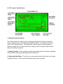
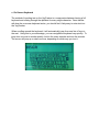
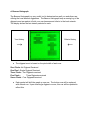
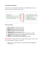
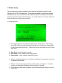
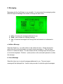
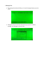
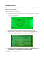
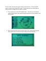
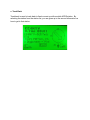
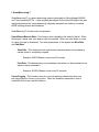
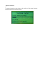
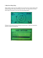
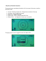
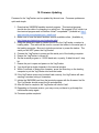
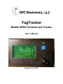
YagTracker
Mobile APRS Terminal and Tracker
User’s Manual
Firmware V1.46 - REV A.
Table of Contents
1. Introduction
2. Package Contents
3. Basic Device Overview
a. User Interface
b. LCD Layout
c. Rotary Encoder Functions
4. Features
a. Screens
b. Menus
c. On-Screen Keyboard
d. Beacon Histograph
Interface
Connections
5.
a. Power
b. Radio
c. GPS
6. Getting Started
a. Powering up for the First Time
b. Mobile Setup
c. Home/Fixed Setup
7. Modem Setup
a. Transmit Audio
b. Receive Audio
8. Messaging
a. Initiate a Message
b. View a Message
c. Message Chat
9. Advanced Features
a. Station List Sorting and Filtering
b. GPS Data View and Waypoint Output
c. Track Back
d. Map Callsign View
e.
f.
g.
h.
i.
j.
k.
l.
10.
Friend List
SmartBeaconing
Fill-In/Relay Digipeater
KISS Modem Mode
NMEA/KISS Dual Mode
System Information
Map Screen Range Rings
Map Screen Detailed Information
Firmware Updating
1. Introduction
Thank you for purchasing a YagTracker! The YagTracker is a full featured APRS
Tracker and Terminal device meant to take the place of a laptop computer in many
mobile APRS applications. The YagTracker started out as a personal project of Remi
Bilodeau VE2YAG. It has since turned into a robust and feature-rich device suited for
even the most demanding mobile APRS user that wishes to have a visual presentation
of the APRS network activity at their fingertips.
The YagTracker compares in many ways to the Kenwood RC-D710 and is a great
alternative at a much smaller price.
2. Package Contents
Upon opening the package, you will find the following items:
●
●
●
●
YagTracker: APRS Terminal
CD-ROM Containing this manual and other useful files
Mating DB9 Male connector
DB9 Hood Kit
3. Basic Device Overview
a. User Interface
The YagTracker has a very simple user interface to eliminate the need for multiple
buttons, knobs and other controls. Learning some simple methods with the rotary
encoder will allow you to navigate the YagTracker’s screens, menus and other functions
with just a spin of of your fingers.
● The Power switch is a micro toggle switch slightly recessed just above the
interface connector. It’s easy enough to get to when powering the unit on or off
and at the same time stays out of your way to avoid accidental switching.
● The LCD Display is a 128x64 pixel graphical display utilizing the industry
standard KS0108 controller.
● The Beacon/Escape button is a quick way to fire off a position packet when in
any screen or use it to exit out of pop-up and setup menus
● The Rotary Encoder is a detent-less (no clicking) rotary control that is used to
switch through screens, menu options, select keys on the on-board keyboard,
control sliders and zoom in/out.
● The Activity LED has tri-color function. It uses GREEN to indicate a received
packet, RED to indicate transmitting of a packet and ORANGE to indicate the
digipeat of your own packet.
b. LCD Layout - Home Screen
c. Rotary Encoder Functions
The rotary encoder is a detent-less (no clicking) encoder with a built-in momentary
switch. Pushing in the on the knob will activate this switch. You will hear and feel a
small “click” when doing this. The momentary switch is used for selecting items in
menus or giving “OK” to a menu selection or setting. When using the rotary function,
there are two basic methods:
1. Rotate Normally - This is typically used when going through menu choices, adjusting
settings and/or scrolling through things like the station list.
2. Rotate with the Button - To do this, you must push in the knob and then turn it while
holding the knob in. This is used for switching from screen to screen.
4. Features
This section of the manual will cover the many features of the YagTracker, including
screen views, menus and other major features useful to the user.
a. Screens
There are currently five screens implemented in the YagTracker firmware. These
screens are:
Home
Station List
Tracking
Chat Messaging
Map Plot
Raw Packet Monitor
b. Menus
There are two kinds of menus used in the YagTracker firmware:
Pop-Up: These menus are activated while on one of the main screens by pushing in
the rotary encoder switch momentary. If a menu is available, it will pop up in a small
window. You can then rotate the rotary encoder to select an item, then click the rotary
encoder button one time to select the item. You may exit the menu by pressing the
Beacon/Escape button momentarily.
Full Screen: These menus are accessed by first using the Pop-Up menu method on
any of the main screens and selecting the Main Menu item in the pop-up menu. This
will bring up a full screen menu with Icons. Selecting an icon and clicking the rotary
encoder’s button will open up the menu associated with the icon.
c. On-Screen Keyboard
The method of inputting text on the YagTracker is a compromise between having a full
keyboard and rotating through the alphabet for every single character. Once familiar
with how the on-screen keyboard works, you should find it fairly easy to enter text into
the YagTracker.
When scrolling around the keyboard, it will automatically jump from one line of keys to
the next. Using this to your advantage, you can navigate the keyboard very quickly. To
jump from one row to another quickly, hold in the rotary encoder and turn the encoder.
The cursor will jump up or down one row, depending on which way you turn it.
d. Beacon Histograph
The Beacon Histograph is a very useful tool to determine how well you and others are
utilizing the local network digipeaters. The Beacon Histograph keep a running log of the
digipeat count per packet of both your own beacons and other’s in the local network.
The display shows the last sixteen packets for each.
Your History
Other’s History
→
←
● The digipeat count is based on the pixel width of each row:
Zero Pixels -No Digipeat Received
One Pixel - Single Digipeat Received
Three Pixels - Two Digipeats received
Five Pixels Three Digipeats received
Seven Pixels - Four Digipeats received
● Each packet will shift the graph up one row. The bottom row will be replaced
with a blank row. Upon receiving a digipeat or more, this row will be updated to
reflect this.
5. Interface Connections
All connections to the YagTracker are made through a single DB9 connector on the
right side of the unit, just below the power switch.
Pinout Descriptions
1.
2.
3.
4.
5.
6.
7.
8.
9.
Modem Transmit - Transmit audio to radio
Modem Receive - Receive audio from radio
Modem PTT - Push to Talk control to radio
GPS Transmit Data - Transmit data to GPS
GPS Receive Data - Receive data from GPS
+5VDC Switched - Switched +5VDC output (controlled by power switch)
VIN Switched - Switched input power output (controlled by power switch)
Voltage In - Input for supply power to YagTracker
Ground - Ground connection (common/shared for all devices)
Warning: Pin 6 is a voltage OUTPUT! Do not apply external voltage to this pin. Doing
so will cause damage to the internal 5V regulator!
● Sections a, b and c have the specific required pin connections highlighted per
external device.
a. Power
b. Radio
c. GPS
6. Getting Started
This section of the manual can serve as a quick-start guide when powering up the
YagTracker for the first time.
a. Powering Up for the First Time
When you power up the YagTracker for the first time, you will be presented with the
station setup menu. This menu is used to set the Callsign, Path, Icon, Comment and
other settings pertaining to your station.
b. Mobile Setup
Callsign - Your callsign + SSID (Example: KE4NYV-15) (SSID is optional)
Path - Path best suited for your APRS network (Example: WIDE1-1,WIDE2-1)
Icon - Sets the icon that will be displayed with your call
Status - Can be any short info for your station (Example: YagTracker V1.5)
MIC-E - This function can be turned on to compress your packet
● To change a setting, rotate the rotary encoder to move the arrow on the left next
to that item. Click in one time to select it. You will be taken to a window and
the on-screen keyboard will be available. Here you can edit this setting. Select
the ↵ (return) button on the keyboard to confirm the edit and return back to the
station setup menu.
c. Home/Fixed Setup
This mode allows for the YagTracker to be operated from a non-mobile environment,
without a GPS connected. To enable this mode, change the “N” to “Y”. Set the callsign,
status text and path. A static longitude and latitude is always required.
7. Modem Setup
There are two menu options available to fine tune the YagTracker modem for use
with any VHF or UHF FM transceiver. The modem is capable of receive and transmit
1200 baud data. The connections can be made through the microphone and external
speaker connections and are fairly forgiving. It’s a good idea to fine tune the settings for
proper deviation and and receive amp gain.
a. Transmit Audio
● The transmit audio is controlled through the menu shown above. The settings
are in dB. Rotate the rotary encoder to set the level. Pressing the rotary switch
in will activate several functions. These functions are activated in a cycle of three
total clicks:
1. One Click - Force Transmit, no tones
2. Two Clicks - Force Transmit, with 1200 Hz tone
3. Three Clicks - Force Transmit, with 2200 Hz tone
● While in the third click function, a fourth click will dekey the transmitter and return
you back to the idle state.
● While in transmit, the rotary encoder can be turned to set the level. It’s ideal to
monitor your transmitter deviation at the same time, if possible.
● Once the setting has been completed, use the Beacon/Escape button to exit out
of the menu.
b. Receive Audio
● The receive audio menu is used to set the internal amplifier gain. There are two
settings:
1. Preamp (Coarse) - Click on the rotary encoder switch to toggle between the four
small boxes in the bottom right.
2. PGA Gain (Fine) - Rotate the rotary encoder to adjust the slider setting.
● Use the on-screen scope view (left side) to watch incoming audio. If you are
running an open-squelch setup, you will have a constant wave fluctuation shown
by the noise coming from the radio. If you are running closed squelch, you
should have a flat line in the middle. Only when you receive a packet should
you see anything on the scope display. Adjust the coarse and fine settings to
achieve a peak of 70-80% when receiving a live packet. Do not set the white
noise level for this value or you will overload the modem when a real packet is
received.
8. Messaging
Messaging with the YagTracker is very versatile. You can access the messaging option
either through the Message Chat screen or through the main menu.
1. Inbox - Contains all messages addressed to you.
2. Send - Use to initiate an outgoing message
3. List - All received messages sent through the local network not addressed to
you.
a. Initiate a Message
Select the Send icon. You will be taken to the station list menu. Rotate through the
station list until you find the station you want to send a message to. Click the rotary
button in to select the station. The next window will be a message input box along with
an on-screen keyboard. Click the ↵ (return) button on the on-board keyboard to confirm
the message.
b. View a Message
Select the Inbox icon to view all messages addressed to you. The most recent
message will be displayed first. Use the rotary encoder to rotate through all messages.
c. Message Chat
● The message chat window will allow you to view all message between you and a
station.
● Clicking the rotary encoder button will present a pop-up menu to initiate a
message, view messages or clear the Inbox.
9. Advanced Features
The advanced features listed in this section are not required to use the YagTracker, but
make using it more enjoyable.
a. Station List Sorting and Filtering
● When viewing the station list, bring up the pop up window will give you the option
to modify the sorting method.
● The station list can be sorted based by distance, time and alphabetically.
Nearest is based on valid GPS data. In order for this to work, a GPS must be
connected and feeding the YagTracker with valid and locked GPS data.
● The station list can also be filtered based on station type. By selecting any of the
filter parameters, all stations pertaining to them will be displayed.
b. GPS Data View and Waypoint Output
On any screen, click the rotary knob to bring up a pop-up menu. Choose the GPS
option to view the first of three GPS screen. Use the push and turn method with the
rotary encoder to change from one screen to another.
● This screen shows current GPS satellite status. It will show you the satellites
currently being tracked, their signal strength and position in the sky relative to the
GPS receiver.
● This screen shows the current Fix Status, Date, Time, Latitude and Longitude.
This screen is live, so it can be left up to display this data in real time.
c. Track Back
Track back is used to track back to fixed or meet up with a mobile APRS station. By
selecting the station from the station list, you are given up to the second information on
how to get to that station.
d. Map Callsign View
When view the Map Plot screen, you can view the callsign and distance of a station by
clicking the rotary encoder switch and choosing the Show Callsign menu option.
● The callsign/range label will start on the station closest to you. Rotate the rotary
encoder clockwise to switch the label from the closest out through progressively
further stations.
● A line will always connect the info box to the plot on the map to indicate which
station is being view currently.
● If the station is out of view, click the rotary encoder knob to bring up the popup menu. Choose Return to go back to the normal Map Plot view. Change the
range of view by rotating the rotary encoder.
e. Friend List
The YagTracker has a Friends List feature that allows for quick recall of those stations
you message, track and view regularly.
Adding a friend to your list is easy by using the pop-up menu when viewing a station
and selecting the “Toggle Friend” option. “(Friend)” is shown on added station detail.
f. SmartBeaconing™
SmartBeaconing™ is a smart beaconing scheme developed by Steve Bragg KA6MVA
and Tony Arnerich KD7TA. It was originally developed for the HamHUD project but was
quickly adopted as the “smart beaconing” algorithm standard now used on countless
APRS tracking devices and hardware.
SmartBeacoing™ has two main components:
Speed Based Beacon Rate - Your beacon rate is based on the speed of travel. When
traveling at a faster rate, your beacon rate is increased. When you slow down or come
to a stop, the rate is decreased. Two main parameters of this aspect are Slow Rate
and Fast Rate:
Slow Rate - This determines the max beacon rate delay when moving below a
certain speed or completely stopped.
Example: 5 MPH Beacon once every 30 minutes
Fast Rate - This determines your max beacon rate when you have reached a top
speed or have exceeded it.
Example: 65 MPH Beacon once every 30 seconds
CornerPegging - This function uses your current heading to determine when you
are going around a corner or long curve. When the threshold parameter is met or
exceeded, this forces a position beacon
g. Fill-In/Relay Digipeater
The YagTracker has a fill-in/relay style digipeater function built in to utilize it in a low
digipeater coverage area.
● Enable the digpeater function by changing the “N” to “Y”.
● Set the alias to a name that will be used in the alternate device’s UNPROTO
path.
NOTE: When using this feature, if the alternate device has the ALIAS ONLY in it’s
path, it will be digipeated by the YagTracker and will not be digipeated by any other
stations. If you wish for the packet to go through a WIDE area digipeater, a path such
as <ALIAS>,WIDE1-1 or <ALIAS>,WIDE2-2 is suggested.
h. KISS Modem Mode
The YagTracker can be used as a KISS modem for both transmitting and receiving
using an external computer or other portable computing device.
Selecting the “Serial Mode” setting will bring up a port mode pop-up menu. Selecting
the “KISS Modem” selection will put the serial port in KISS mode.
Selecting the “Serial Speed” setting will bring up a pop-up menu to select the port baud
rate.
i. NMEA/KISS Dual Mode
Selecting the port mode option “Dual (NMEA in, KISS out)” will allow you to feed GPS
NMEA data to the YagTracker and output all received packet data in KISS format.
This mode is for mobile use, when a full mapping APRS client is preferred for a more
detailed display, but tracking mode through the YagTracker is still desired.
Using this mode is very useful for those who would like to connect a mobile computing
device on the run, without having to reconfigure the YagTracker everytime. In
this mode, the external device is transparent since it’s not sending any data to the
YagTracker, simply using the KISS output from the YagTracker as a live data feed of all
on-air data received via RF.
j. System Information
The system information screen shows you the overall use of the system’s memory,
transmitted packets and received packets.
k. Map Screen Range Rings
When enabled, range rings can be added to the map plot screen to show stations at the
displayed range (outer ring) and half range (inner ring). The range distance shown in
the top right of the screen is the current outer ring range distance.
Clicking in on the rotary encoder will bring up a pop-up menu. Select the map options
selection to enable the range rings.
l. Map Screen Detailed Information
The map plot screen can display information in all four corners of the screen, as well as
the bottom center.
●
●
●
●
●
Top Left - Rotating compass rose. Always shows orientation of the map.
Top Right - Current range being viewed.
Bottom Left - Digipeat Histograph.
Bottom Right - GPS Fix Status/Locked Sats Count.
Bottom Center - Last digipeater to beacon your own packet.
The pop-up menu is used to toggle the corner info objects off/on.
10. Firmware Updating
Firmware for the YagTracker can be updated by the end user. Firmware updates are
quick and simple.
1. Download an XMODEM capable terminal program. This terminal program
should also be cable of connecting to a serial port. We suggest UCon, which is a
free terminal program and is Windows Vista/7 compatiable. (Available at: http://
www.umonfw.com/releases/ucon_install.exe)
2. Make sure to have the latest firmware version available online. (Available at
http://www.rpc-electronics.com/yagtracker.php)
3. Using the same pins used to connect the GPS to the YagTracker, construct a
loading cable. This cable will be used to connect the tracker to the serial port of
the loading computer. Be sure to include provisions to power the tracker. The
serial port will NOT power the YagTracker.
4. Connect the YagTracker to power and the serial port of the loading computer.
5. Ensure the YagTracker is turned off.
6. Set the terminal program to 115200 baud rate, no parity, 8 data bits and 1 stop
bit.
7. Ensure the port is open and power on the YagTracker.
8. You should get a single character in the terminal window.
9. Within 3 seconds of seeing this character, press the Enter key on the loading
computer to put the YagTracker into bootload mode.
10. If the YagTracker enters into bootload load correctly, the YagTracker will start
sending a constant string of characters.
11. Initiate the XMODEM load from the terminal program with the firmware .bin file.
The YagTracker should accept the file automatically.
12. After the load is complete, the YagTracker will reboot it’self.
13. Depending on firmware version, you may or may not have to go through the
initial tracker setup again.
14. Firmware update complete!