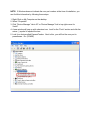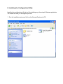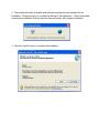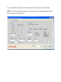
1
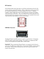
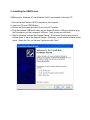
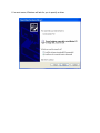
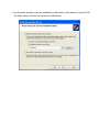
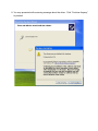
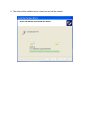
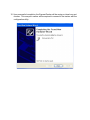
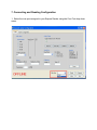
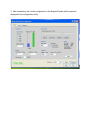
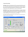
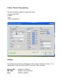
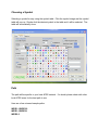
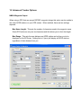
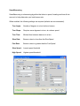
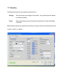
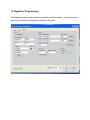
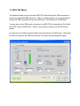
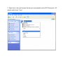
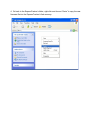
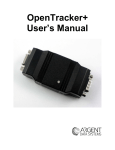
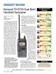
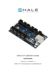
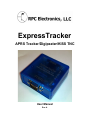
ExpressTracker APRS Tracker/Digipeater/KISS TNC User Manual Rev A. Table of Contents 1. 2. 3. 4. 5. 6. 7. 8. 9. 10. 11. 12. 13. 14. 15. Introduction Package Contents Device Overview Interface Connections, Switches and Jumpers Installing the USB Drivers Installing the Configuration Utility Connecting and Reading Configuration Audio Codec Setup Basic Tracker Programming Advanced Tracker Options Telemetry Digipeater Programming KISS TNC Mode KISS/NMEA Pass Through Mode Updating Firmware 1. Introduction Thank you for purchasing the ExpressTracker! This is a brand new APRS device that has multiple uses. As a tracker, a digipeater or a KISS TNC. You can even mix and match modes to run at the same time. The ExpressTracker is a collaborative effort between RPC Electronics, LLC and Remi Bilodeau VE2YAG (Firmware/Software Engineer). Many thanks to the individuals who helped up with the testing and refining of the ExpressTracker: Shaena Hicks KI4UDD Bryan Sams N0BES 2. Package Contents Upon opening the package, you will find the following items: ● ExpressTracker ● USB A to Mini B Cable ● Mini CD containing the user’s manual, configuration utility and USB drivers 3. Device Overview The ExpressTracker is a new multiuse APRS device designed around solid hardware and specific functions in mind. The ExpressTracker can be a simple tracker, a two way tracker, a digipeater and a KISS TNC for advanced software function. The ExpressTracker in some configurations can be all of these functions at the same time. Radio/USB Panel Serial/GPS Panel 4. Interface Connections, Switches and Jumpers Radio Connector GPS/Serial Connector DIP Switches On the Radio Interface side of the tracker, you will find a small opening to the left of the connector with two recessed DIP switches. Switch 1 (left side) is used to put the tracker into a special bootloading mode for firmware upgrades (See section 13: Updating Firmware). Switch 2 (right side) is used to connect the push to talk line to the transmit audio line through a 3.3K resistor. This is only needed when the radio being used has a combined transmit audio and push to talk mic connection. This is typically found on most Yaesu/Icom/Alinco style handhelds, as well as some mobiles. USB Mini Connector The ExpressTracker’s mini USB connector is used for several functions: Configuration, KISS TNC operation and Firmware Updating. The connector is a standard mini USB connector and compatible with standard USB A to Mini B cables. Important! When connecting the ExpressTracker to a computer for the first time, be sure to have the USB drivers available either via the included CDROM or already copied to the computer. When the driver wizard pops up, you’ll need to point the wizard to the location of the driver files. GPS Power Jumper The GPS Power Jumper is used to provide DC voltage to an external GPS. The jumper is accessed by removing the two bottom panel screws and opening the ExpressTracker’s case. The jumper can be set to one of three positions: 5 Volt Output to GPS: Source Voltage Output to GPS: No Voltage to the GPS: 5. Installing the USB Drivers USB drivers for Windows XP and Windows Vista/7 are included on the mini CD. 1. Ensure ExpressTracker is NOT connected to the computer. 2. Insert mini CD into CDROM drive. 3. Ensure the Bootloader dip switch is set to the OFF position. 4. Plug the included USB Mini B cable into the ExpressTracker’s USB port and then plug the A connector into the computer’s USB port. (Any unused port will work) 5. Wait for Windows to detect the ExpressTracker. At this point Windows may install a suitable driver to talk to the ExpressTracker. Otherwise, you will see the window shown below. Select the “No, not this time” option and click “Next”. 6. In most cases, Windows will ask for you to specify a driver. 7. Use the driver wizard to point the installation to the location of the drivers on the mini CD. The folder named “Drivers” will contain the USB drivers. 8. You may presented with a warning message about the driver. Click “Continue Anyway” to proceed. 9. The driver will be installed and a virtual com port will be created. 10. Upon successful completion, the ExpressTracker will be assign a virtual com port number. This com port number will be required to connect to the tracker with the configuration utility. NOTE: If Windows does not indicate the com port number at the time of installation, you can find this information by following these steps: 1. RightClick on My Computer on the desktop. 2. Select “Properties” 3. Click “Device Manager” tab in XP or “Device Manager” link in top right corner for Vista/7. 4. A new window will pop up with a devices tree. Look for the “Ports” section and click the minus () symbol to expand the tree. 5. Look for a device called ExpressTracker. Next to this, you will find the com port in parentheses. Ex. (COM22) 6. Installing the Configuration Utility Installing the configuration utility is just like installing any other simple Windows application. The wizard will walk you through the process. 1. Run the installation setup.exe file from the ExpressTracker mini CD. 2. The installer will verify all system and software requirements are available for the installation. Setup may ask you to install the Microsoft .Net framework. If this is requested, complete this installation first and then the ExpressTracker will complete installation. 3. Click the “Install” button to complete the installation. 4. Upon installation completion, the configuration utility will start up automatically. NOTE: All of the settings will appear to not function since the ExpressTracker has not been read yet for initial settings. 7. Connecting and Reading Configuration 1. Select the com port assigned to your ExpressTracker using the Com Port drop down menu. 2. Click the “Connect” button. 3. After connecting, the current configuration in the ExpressTracker will be read and displayed in the configuration utility. 8. Audio Codec Setup Audio Input Start with “Input Preamp” set at 0 dB. In many cases, this will be the correct level. With the radio in open squelch (static noise present) observe the Input Level bar to right. The level bar should be “jumping” up and down with the noise. If the bar is pegged to the top and never moves, adjust your audio input. If the radio has a fixed level, use the in PGA gain setting to add in slight attenuation to achieve the desired behavior. Audio Output The output audio can usually be adjusted by ear, if no means of measuring the deviation is available. In general, set the level to match that of other stations on the air. This is done by adjusting the Codec Output Level slider. To test the level, use the 1200 Hz and 2200 Hz buttons to send test tones over the air. We suggest that you do this off of your country’s APRS frequency, to avoid interference with other stations. Once both the input and output levels are set, use the “Write” button in the bottom right to program the tracker with these settings. 9. Basic Tracker Programming The minimal settings needed to program the tracker: Callsign (and SSID) Symbol Path Beacon Rate/Method Callsign The callsign used should be a valid amateur radio callsign or alias (for an event). The callsign may or may not contain an SSID on the end. Some examples: Without SSID: With SSID: Alias: KE4NYV or VE2YAG KE4NYV15 or VE2YAG4 WATER or BIKE12 Choosing a Symbol Selecting a symbol is easy using the symbol table. Click the symbol image and the symbol table will pop up. Simple click the desired symbol in the table and it will be selected. The table will automatically close. Path The path will be specific to your local APRS network. If in doubt, please check with other local APRS users for the best path to use. Here are a few universal sample paths: WIDE11,WIDE22 WIDE11,WIDE21 WIDE22 10. Advanced Tracker Options NMEA Waypoint Output When using a GPS that can accept $GPWPL waypoint strings this option can be enable to see other APRS stations on your GPS screen. When enabled, there are two settings required: Max Name Length: This sets the number of characters used in the waypoint name. Some GPS units can only use six characters and this allows your to limit the length. Max Range: This sets the max distance an APRS station can be from you to be displayed on the GPS map. Setting this to 0 (zero) will display all APRS stations, regardless of their distance from you. SmartBeaconing SmartBeaconing is a beaconing algorithm that takes in speed, heading and time all into account, to help determine your best beacon rate. When enabled, the following settings are required (defaults are recommended): Turn Angle: Number of degrees in a turn before a beacon Turn Slope: Requires more degrees in a turn, at a slower speed Turn Time: Minimal time between beacons in a turn Slow Rate: Beacon rate at or less than the Slow Speed Fast Rate: Beacon rate at or greater than the Fast Speed Slow Speed: Lowest speed threshold High Speed: Highest speed threshold 11. Telemetry The ExpressTracker has two telemetry options built in: Voltage: This reports the input voltage to the tracker. Very useful when the tracker is running on battery. Temp: The onboard temp sensor will report the ambient air in either Fahrenheit or Celsius. Both telemetry options are reported in the beacon comment section in the following format: V=00.0 T=00.0F or T=00.0C 12. Digipeater Programming The Digipeater function can operate in conjunction with the tracker. You can choose to have each use their own callsign and symbol or the same. 13. KISS TNC Mode The ExpressTracker can be used as a KISS TNC either through the USB connection or through the serial/GPS DB9 connector. When in normal operation (not in programming mode), the USB connection will serve as KISS port. The baud rate is 19,200 baud. You may also use the DB9 serial connection as a KISS TNC by changing the Port Mode from GPS In/Out to KISS In/Out. When in this mode, you cannot use a GPS with the tracker. In most cases, the USB connection will be the best selection for KISS mode. The tracker can also be power by the USB port and does not require an external power supply. 14. KISS/NMEA Pass Through Mode When using the ExpressTracker as a KISS TNC through the USB port, you can also have a serial GPS connected to the serial port and pass that data through to the USB port and on to the computer. This is streamlines your setup down to a single USB connection between your ExpressTracker, GPS and computer. This is especially useful in a portable or mobile environment. Enabling this function is easy. Simply check the “Enable NMEA Pass Through” check box option in the “Serial Port” frame, under the Codec tab: 15. Updating Firmware 1. If you haven’t already, go to http://www.rpcelectronics/et/firmware.php to download the latest ExpressTracker firmware. Save the firmware file to a known location on your computer. 2. Unplug the ExpressTracker from the USB port and make sure there are no other power sources going to the tracker. Switch the BOOTLOADED DIP switch to the ON position and plug it into the USB port of your computer. 2. A window should automatically pop up showing the contents of the ExpressTracker flash memory. The file shown should be “firmware.bin”. Right click on this file and choose “Delete”. 3. Right click on the new firmware file that you downloaded from the RPC Electronics, LLC website and choose “Copy”. 4. Go back to the ExpressTracker’s folder, right click and choose “Paste” to copy the new firmware file into the ExpressTracker’s flash memory. 5. Once you have copied the firmware file into the ExpressTracker, you should see the file residing in the folder. 6. Unplug the ExpressTracker from the USB port of your computer. 7. Flip the BOOTLOADER DIP switch back to the OFF position. 8. Upon the next power up, the new firmware will selfload itself and your ExpressTracker will now have updated firmware. NOTE: In most cases, all settings will be retained. In some some special firmware updates, the EEPROM memory may be erased and remapped and you will be required to reconfigure your tracker’s settings after the update.