1
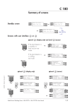
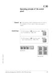
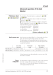
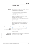
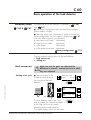
C 60
Basic operation of the leak detector
Preliminary about
C 60 &
C 61
The operation of the leak detector is explained in
C 60
and
C 61.
■ If the factory configuration does not need to be changed,
please read this chapter.
■ If operator needs more information or needs to change the
C 61
factory configuration, he must read this chapter and
where the following points are explained:
➪ hard vacuum test mode (information)
➪ selecting a test mode
(adjustment)
➪ sniffer probe
(information)
➪ sniffer probe reject point (adjustment)
Factory configuration
C 10
Two test methods are possible with the leak detector:
➪ hard vacuum test
➪ sniffing test.
Hard vacuum test
Starting a test cycle
Make sure that the parts can withstand the
difference in internal / external pressure to which
they are subjected.
Connect the part or the
installation to be tested to
the inlet port of the leak
detector.
■
F1
READY FOR CYCLE
F3
INLET:
vent off
F2
F4
STDBY
10 -2
10 -3
GB 01362 - Edition 01 - December 01
10 -4
COR
ZERO
10 -5
10 -6
INLET
10 3
10 2
10 -7
TEST
10 -8
HIGH
10 1
10 -1
CYCLE
10 -10
SNIF
10 -3
F3
CYCLE IN PROGRESS
MODE:
roughing
INLET ...
10 -11
10 -2
mbar
F1
10 -9
1
VENT
F2
F4
10 -12
mbar.l/s
CYCLE
AUTO CAL
ZERO
or
F1
F3
CYCLE IN PROGRESS
MODE:->
high sens
INLET ...
The leak detector reaches the Gross
Leak test mode, the Normal test mode
or the High Sensitivity test mode
according to test mode selection.
The digital display shows the leak value.
Alcatel Vacuum Technology France - ASM 182 TD+ - ASM 192 T2D+ User’s Manual
F2
F4
TEST
1/3
C 60
Basic operation of the leak detector
Leak value
on digital display
LEAK RATE
Whatever the test mode.
COR
Control panel
Leak value on
analog display
10 -12
10 -11
10 -10
Remote control
10 -9
10 -8
10 -7
10 -6
10 -5
10 -4
10 -3
10 -2
10 -2
10 -3
10 -4
reject point
10 -5
The helium signal analog scale displays the leak
value in 2 colors following the measured leak value:
➪ reject point is visualized by a blinking led.
➪ if the leak value exceeds the reject point, the leds
will turned red (the blinking led will turn orange).
➪ if the leak value remains under the reject point,
the leds will remain green.
10 -6
10 -7
10 -8
10 -9
10 -10
10 -11
10 -12
mbar.l/s
When the bargraph zoom is ON, the leak value
display is different. It shows 2 decades of signal as compare
to the entire leak range when the bargraph zoom is off.
10 -2
Bargraph zoom
C 90
Reject point
C 100
10 -3
10 -4
COR
ZERO
10 -5
10 -6
INLET
10 3
10 2
10 -7
TEST
10 -8
HIGH
10 1
Ending
a test cycle
10 -9
1
10 -1
10 -10
SNIF
10 -11
10 -2
mbar
10 -3
VENT
10 -12
mbar.l/s
F1
READY FOR CYCLE
F3
INLET ...
F2
CYCLE
CYCLE
AUTO CAL
ZERO
F4
or
Venting the part or
installation tested
2/3
At the end of a test cycle, 2 possibilities are available:
➪ venting (inlet of the leak detector is back to atmospheric
pressure)
➪ not venting (keeping under vacuum) the part or tested
installation remains under vacuum.
Vent air
C 80
Alcatel Vacuum Technology France - ASM 182 TD+ - ASM 192 T2D+ User’s Manual
GB 01362 - Edition 01 - December 01
STDBY
In standby the digital display shows
the leak detector helium background.
Remark: If Cycle end function is activated, the test cycle end
is different.
Cyle end function
C 110
C 60
Basic operation of the leak detector
Sniffing test
Reminder
Operating principle of the control panel
Press the key
Starting
a sniffing test
While the leak detector is in
stand-by mode, connect the
sniffer probe (accessory to
be purchased separately) to the
sniffer port of the leak detector.
C 20
activated
F1
READY FOR CYCLE
F3
INLET ...
F2
F4
STDBY
SNIFFER
F1
SNIFFING MODE
PLEASE WAIT
...
F2
F3
F4
GB 01362 - Edition 01 - December 01
The sniffing mode message
F1
appears on the alphanumeric F3
display.
The sniffing test mode is operational.
Leak value
display
Ending
a sniffing test
SNIFFING MODE
F2
F4
Digital and analog displays are the same in hard vacuum and
sniffing test modes.
Please refer to hard vacuum test mode for the displays.
SNIFFER
F1
READY FOR CYCLE
F3
INLET ...
F2
F4
STDBY
Alcatel Vacuum Technology France - ASM 182 TD+ - ASM 192 T2D+ User’s Manual
3/3