1
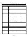
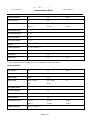
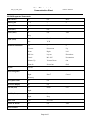
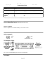
IP Link® De vice Interface
Communication Sheet
tand_12_3423_4.pke
Revision: 2/28/2011
This document provides additional assistance with wiring your Extron IP Link enabled product to your device.
Different components may require a different wiring scheme than those listed below.
For complete operating instructions, refer to the user’s manual for the specific Extron IP Link enabled product or
the controlled device manufacturer supplied documentation.
Device Specifications:
Device Type:
Manufacturer:
Firmware Version:
Model(s):
Video Conference
T andberg
F6.1
Edge 85 MXP, Edge 95 MXP, Edge 75 MXP
Version History:
Driver
Version
Date
IP Link
Compiler
GC
Version
4
2/21/2011
1.4.0
3.0.4
Extron Certified. Added IR Remote Emulation command.
3
01/13/2010
1.4.0
3.0.2
Extron Certified. T ested on Edge 95 MXP. Added Auto Focus,
Power Control and Camera Id for auxiliary camera control.
2
06/12/2009
1.3.11.1
2.5.1
Extron Certified. T ested on Edge 95 MXP. Updated several
commands. Added far end input and camera control.
1
03/23/2009
1.3.11.1
2.5.0
Extron Certified. T ested on Edge 95 MXP.
Notes
Driver Notes:
Camera Control Commands are all Press-Release buttons where controls are activated when the button is pressed
and stops once the button is released. The “ Stop” command is for configuration purposes.
Driver is not recommended with pass-through mode.
‘IR Remote Emulation’, ‘Dial Keypad’ and ‘Menu Navigation’ simulate the IR codes of the remote.
Asterik(*) is also used as a period.
Page 1 of 5
IP Link® De vice Interface
Communication Sheet
tand_12_3423_4.pke
Revision: 2/28/2011
Control Commands & States:
Auto Answe r
On
Off
Mute
Camera Id
1-13
Dial Keypad
0 –9
*
#
Display Mode
Single
Dual
Focus (Far)
In
Out
Focus (Near)1
In
Out
Auto
PC
Stop
Input (Far)
0 – 15
Input (Near)
Main Camera
Doc Camera
Aux
VCR
0-9
*
#
Connect
Disconnect
Up
Down
Right
Left
Selfview
Layout
Phonebook
Cancel
Mic Off
Presentation
Volume Up
Volume Down
OK
Zoom In
Zoom Out
Grab
IR Remote Emulation
Layout
Execute
Menu Navigation
Up
Down
Left
Right
Enter2
Cancel
Directory
Microphone Mute
On
Off
On Screen Display
On
Off
Pan-Tilt (Far)
Up
Down
Left
Up
Down
Left
Right
Stop
Call
End Call
Right
Pan-Tilt (Ne ar) 1
Phone Call
Page 2 of 5
IP Link® De vice Interface
Communication Sheet
tand_12_3423_4.pke
Revision: 2/28/2011
Picture In Picture
On
Off
Powe r Control
On
Off
Pre sentation Source
Current
Video 1
Video 2
Video 3
Video 4
Video 5
Pre set Re call (Far)
0 – 15
Pre set Re call (Near)
0 – 14
Pre set Save (Far)
0 – 15
Pre set Save (Ne ar)
0 – 14
Selfvie w
Off/On
Volume (Discre te)
0 to 21 in steps of 1
Volume (Ste p)
Up
Down
Zoom (Far)
In
Out
In
Out
Zoom (Near)1
1. Will control camera with the selected camera Id.
2. This command serves the same function as the OK/Menu button on the remote
Auto
Stop
Status Available:
Auto Answe r
On
Off
Connection Status
Connected
Disconnected
Display Mode
Single
Dual
Input (Near)
Main Camera
Doc Camera
Aux
VCR
Microphone Mute
On
Off
On Screen Display
On
Off
Picture In Picture
On
Off
Powe r Control
On
Off
Pre sentation Source
Current
Video 1
Video 2
Video 3
Video 4
Video 5
Volume (Discre te)
0 to 21 in steps of 1
Page 3 of 5
Mute
PC
Auto
IP Link® De vice Interface
Communication Sheet
tand_12_3423_4.pke
Revision: 2/28/2011
MLC62 Supported Commands:
Auto Answe r
On
Off
Mute
Dial Keypad
0 –9
*
#
Display Mode
Single
Dual
Focus (Far)
In
Out
Focus (Near)1
In
Out
Auto
Main Camera
Doc Camera
PC
Aux
VCR
0-9
*
#
Connect
Disconnect
Up
Down
Right
Left
Selfview
Layout
Phonebook
Cancel
Mic Off
Presentation
Volume Up
Volume Down
OK
Zoom In
Zoom Out
Grab
Stop
Input (Near)
IR Remote Emulation
Layout
Execute
Menu Navigation
Up
Down
Left
Right
Enter2
Cancel
Directory
Microphone Mute
On
Off
On Screen Display
On
Off
Pan-Tilt (Far)
Up
Down
Left
Up
Down
Left
Right
Stop
Phone Call
Call
End Call
Picture In Picture
On
Off
Powe r Control
On
Off
Right
Pan-Tilt (Ne ar) 1
Page 4 of 5
Auto
IP Link® De vice Interface
Communication Sheet
tand_12_3423_4.pke
Revision: 2/28/2011
Selfvie w
Off/On
Pre sentation Source
Current
Video 1
Video 2
Video 3
Video 4
Video 5
Volume (Ste p)
Up
Down
Zoom (Far)1
In
Out
1. Will control camera with camera Id 1
2. This command serves the same function as the OK/Menu button on the remote
Cable and Adapter Requirements:
M/F RS-232 Straight Serial Cable (Extron Electronics P/N: 26-433-XX)
Notes for the Device:
Device can support up to 13 cameras if Tandberg video switchers are used.
Serial communication:
Port Type : RS-232
Baud Rate: 9600
Data Bits: 8
Parity: None
Stop Bits: 1
Flow Control: None
Pin Assignments Diagram:
Note: Captive screw connector may also be used as a serial connection.
General Notes:
Page 5 of 5