1
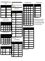
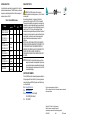
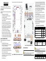
OEM Development Kit 1. Figure 1 shows the location of the Dev Kit connectors and indicators. QUICK START GUIDE The OEM Development Kit (Dev Kit) provides a convenient way to access OEM6™, OEMV3G™ or OEMV™ input and output signals. 2. BOX CONTENTS 3. In addition to this Quick Start Guide, the following is provided with your OEM6 Dev Kit: • PCB assembly (NovAtel Part #01018801) • Two 200mm MMCX R/A plug to MMCX R/A plug coaxial cables (Novatel Part #01018835) • One 150mm MMCX R/A plug to MCX R/A plug coaxial cable (Novatel Part #01018836) • Dev Kit power assembly cable (NovAtel Part #01018570) • 6ft USB cable type A to mini B 5-pin (NovAtel Part #60723111) • 6ft null modem cable (Novatel Part #01017658, may contain DEHP), DB-9 female/female, to connect to COM1, COM2 or COM3. Users will provide cables for COM1-RS422, AUX, CAN1 and CAN2 connection, as necessary. • Five adhesive rubber feet (NovAtel Part #28325059) • Eighteen 2mm pitch jumpers (NovAtel Part #21623400) • Six M3x0.5x12mm Hex Stand-offs (NovAtel Part #28423180) • Four M3x0.5x14mm Hex Stand-offs (NovAtel Part #28423060) • Twelve M3x0.5x6m Philips Screws (NovAtel Part #28523028) 4. 5. 6. 7. 8. Table 1: Receiver Card Type Jumper Positions Receiver Card Type P301 P1001 OEM615™/OEMV1™/OEMSTAR™ Pins 1-2 No Jumper OEMV3G™ Pins 3-4 Jumper OEM628™/OEMV2™ Pins 5-6 No Jumper Reserved Pins 7-8 No Jumper Table 2: Ext. ANT/LNA Power Jumper Positions ADDITIONAL EQUIPMENT REQUIRED Depending on the application, some or all of the following will be required: • OEM6, OEMV3G or OEMV series receiver • A Microsoft Windows-based computing device with a RS-232 DB-9, USB port or 10/100BASE-T port • A +4.5 to 24 V DC power supply, capable of at least 10W A quality GNSS antenna, such as those shown in Table 13. • A 50 ohm coaxial cable with a male TNC connector at the Dev Kit end, for connecting to the ANT port • If necessary, a 50 ohm coaxial cable with a male BNC connector at the Dev Kit end, for connecting to an EXT OSC port (see External Oscillator on page 2) • An RJ-45 Ethernet cable If you have not done so already, install NovAtel PC utilities (Connect and Convert4) on your computing device. These utilities are available from Support | Firmware/Software and Manuals | Product Updates on the NovAtel Web site. Affix the rubber feet (or standoffs) to the underside of the Dev Kit board, on the white landing pads, to avoid potential damage. Jumper the board as necessary, as outlined in Table 1 through Table 7 and any CAUTION notes found below. Place the Dev Kit on a flat surface so that it is supported, for example, by the rubber feet. Install one of the supported OEM receivers on the Dev Kit board. Set the power supply to 4.5 to 24 VDC, then turn off the power. Connect the power cord to the Dev Kit and to the power supply, then turn on the power supply. Connect the Dev Kit to other equipment (antenna, for example), as necessary, as illustrated in Figure 2. You can connect to other equipment with the power on. Shorted Pins P101 1-2 P103 OEM615/OEMV1/OEMSTAR Ant./LNA Int. Pwr. EN OEMV3G™ Ant./LNA Int. Pwr. EN Figure 2: Connecting to the OEM6 Dev Kit USING THE OEM DEV KIT Figure 1: OEM6 Dev Kit Connector and Indicator Locations CAUTION: Follow the ESD practices outlined in Appendix B of the OEM6 Family Installation and Operation User Manual. CAUTION: Do not connect P101 or P102 if you have an external voltage on the Ant/LNA feed cable. Table 3: CAN BUS Jumper Positions Shorted Pins P501 1-2 P502 P503 P504 CAN1 120Ω CAN1 120Ω Opt. CAN 3V3 Opt. CAN 3V3 Table 4: OEM615™/OEMV1™/OEMSTAR™ IO Type Jumper Positions P102 CAUTION: Do not connect P503 or P504 if you have an external voltage on the CAN bus. P102 Pins 1-2:EVENT1 (615/V1/STAR) 1 Pins 9-10:COM3-RX (615/V1) Pins 5-6:EVENT2 (615/V1) Pins 13-14:CAN1-RX (615/V1) O R O R O R O R Pins 3-4:COM3-TX(615/V1)1 Table 8: Dev Kit Connectors Pin COM1 COM2 COM3 AUX Pin Description 1 NC NC NC EVENT1 1 Reserved 2 RXD1 RXD2 RXD3 EVENT2 2 D- Pins 11-12:USB-D+ (615/V1/ STAR) Connector Description 3 TXD1 TXD2 TXD3 Reserved 3 D+ Pins 7-8:CAN1-TX (615/V1) COM1,COM2 & COM31 DB-9 male 4 NC NC NC PPSOUT 4 Reserved Pins 15-16:VARF (615/V1/STAR) AUX2 DB-9 female 5 GND GND GND USER_RESET 5 GND CAN1 & CAN2 DB-9 male, providing support for CAN bus 6 NC NC NC GND EXTERNAL OSCILLATOR USB USB Mini AB 7 RTS1 RTS2 NC VARF ETHERNET RJ45, 10/100BASE-T 8 CTS1 CTS2 NC Reserved Switch to configure COM1 as RS232 or RS422. Setting takes effect on power cycle. 9 NC NC NC GND RS-232/RS-422 SW Some applications require greater precision than that possible with the OEM6™ VCTCXO, in which case you may need to connect the OEM6™ to an external high-stability oscillator, either 5MHz or 10MHz. For further information, refer to Chapter 3 Installation, OM-20000128 OEM6™ Family Installation and Operation User Manual. 1.Enable COM3 INTERFACEMODE sotware command. Table 5: AUX IO Jumper Positions Receiver Card Type Table 12: USB Connector Pin-Outs Table 10: COM/AUX Connector Pint-Outs EVENT1 EN EVENT2 EN PPSOUT EN VARF EN P401 P401 P402 P402 OEM615/OEMV1 Pins 1-2 Pins 9-10 Pins 1-2 Pins 9-10 OEMV3G Pins 3-4 Pins 11-12 Pins 3-4 Pins 11-12 PWR Connector power cord to this connector Pin CAN1 CAN2 OEM628/OEMV2 Pins 5-6 Pins 13-14 Pins 5-6 Pins 13-14 RST Press button to perform soft reset on card 1 NC NC ANT TNC female connector 2 CAN_L CAN_L EXT OSC BNC female connector (applications involving a customer provided external oscillator). 3 GND GND 4 NC NC 5 GND GND Table 6: COM1 Port Jumper Positions Receiver Card Type P507 Pins 1-2 P507 Pins 3-4 P507 Pins 5-6 P507 Pins 7-8 OEM615/OEMV1 Jumper Jumper Jumper Jumper OEMV3G No Jumper No Jumper No Jumper No Jumper OEM628/OEMV2 No Jumper No Jumper No Jumper No Jumper Table 7: OEM628™ IO Type Jumper Positions Shorted Pins P201 P202 P203 1-2 628EVENT2 OEMV3G RS422 ON POWER UP I2C_SCL 2-3 628COM3(0)1 628COM3(1)1 I2C_SDA 2. Configure COM1, COM2 and COM3 baud rate with SERIALCONFIG command (300 to 921600 bps). Table 9: Dev Kit Status LEDs Table 11: CAN1/CAN2 Connector Pin-Outs 6 GND GND Indicator RED Indictor GREEN Indicator 7 CAN_H CAN_H CR801 RS422 Reserved 8 NC NC CR802 ERROR PWRGD 9 OPTIONAL 3V3 (see Table 3) OPTIONAL 3V3 (see Table 3) CR803 /USER_RESET Reserved CR804 COM13 Tx is active COM13 Rx is active CR805 COM2 Tx is active COM2 Rx is active CR806 COM3 Tx is active COM3 Rx is active 3.COM1 only supports RS232 operating mode. ANTENNA SELECTION REGULATORY NOTICE An active antenna is recommended to compensate for the cable loss between the antenna and receiver. The GNSS antenna you choose will depend on your particular application. NovAtel offers a wide range of antennas, as shown in Table 13: WARNING!: The OEM Development Kit is an electronic subassembly intended for evaluation purposes only - it is not a finished end-user product. As an electronic subassembly, it is not subject to the technical requirements for CE marking or for CFR47 FCC Part 15, subpart B. This equipment is intended for use in a laboratory test environment only. It generates, uses, and can radiate radio frequency energy and has not been tested for compliance with the limits of digital devices pursuant to subpart B of part 15 of FCC rules, which are designed to provide reasonable protection against radio frequency interference. Operation of this equipment in other environments may cause interference with radio communications, in which case the user at his own expense will be required to take whatever measures necessary to correct this interference. NOVATEL SHALL NOT BE LIABLE FOR ANY LOSS, DAMAGE OR EXPENSE OF COMPANY ARISING DIRECTLY OR INDIRECTLY OUT OF THE COMPANY'S USE OF THE EQUIPMENT UNDER THIS AGREEMENT. IN NO EVENT SHALL NOVATEL BE LIABLE TO THE COMPANY FOR SPECIAL, INDIRECT, INCIDENTAL OR CONSEQUENTIAL DAMAGES OF ANY KIND OR NATURE DUE TO ANY CAUSE. NOTE: The OEM Dev Kit is not intended to be used as a reference Table 13: NovAtel GNSS Antennas Models ANT-35C1GA-TW-N ANT-26C1GA-TBW-N ANT-35C2GA-TW ANT-A72GA-TW-N ANT-C2GA-TW-N GPS-702L ANT-A72GLA4-TW-N ANT-A72GLA-TW-N GPS-701GGL ANT-A71-GLA4-TW GPS-701-GG GPS-702-GGL, ANT-A72GOLA-TW GPS-702-GG GPS-703-GGG Frequencies Supported GPS L1 only L1 and L2 L1 and L2 plus L-band L1 plus Lband L1 only L1 and L2 plus L-band L1 and L2 L1, L2, L5, E5a and E5b GLONASS Galileo OEM Dev Kit Quick Start Guide: design for implementation in end applications. Original component manufacturer design recommendations should be sought before incorporating any components used on the Dev Kit into an end application design. QUESTIONS OR COMMENTS The Dev Kit BOM, schematics and assembly drawings are available on the Support page of the NovAtel Web site. If you have any questions or comments regarding your OEM Dev Kit, please contact NovAtel using one of these methods: Email: [email protected] Web: www.novatel.com Phone: 1-800-NOVATEL (U.S. & Canada) 403-295-4900 (International) Fax: 403-295-4901 NovAtel is a registered trademark of NovAtel Inc. OEM6 is a trademark of NovAtel Inc. All other brand names are trademarks of ttheir respective holders. ©Copyright 2011 NovAtel Inc. All rights reserved. Printed in Canada on recycled paper. Recyclable. Unpublished rights reserved under international copyright laws. GM-14915099 Rev 2 2011 December