1
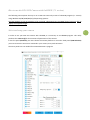
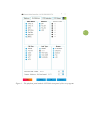
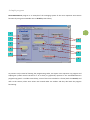
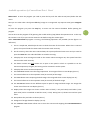
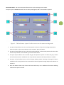
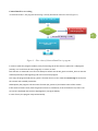
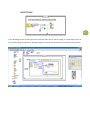
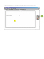
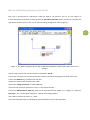
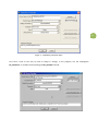
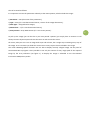
HowtoruntheDTACCDCameras
withLabVIEW
R. Stellacci, R. Grassi
March 2014
1
Copyright 1996‐2014 Digital Technology Art s.r.l. All rights reserved. The reproduction of any part of this notes is allowed only with the written authorization by Digital Technology Art s.r.l. The contents of this manual may be subject to changes without any warning. Digital Technology Art s.r.l. are not responsible for errors that may occur in this manual. Revision 1.1 by Monica Sanna dated 01/03/2004 Revision 2.0 by Renzo Grassi dated 08/02/2014 CONTENTS
Introduction
4
How to run the DTA CCD Camera with LabVIEW
5
Select and setup your camera
5
A Simple program
7
Available operations by CameraDemoTest.vi Panel
8
How to call the library function of the dcl.dll
13
3
Introduction
LabVIEW is a graphical development environment, developed by National Instruments. It is available for Windows, Mac OS, Linux and for various Unix platforms. It allows one to develop applications in a graphical manner using its own programming language. LabVIEW applications are not text‐based, instead they are “drawn” graphically providing a diagrammatic view of how the data flows through the application. This way the typical complexity of traditional programming languages can be avoided. LabVIEW is used in science and engineering for signal acquisition, measurement analysis, and data presentation. A LabVIEW application, for example, can control temperature measurements, analyse the waveforms provided by an oscilloscope and present the acquired results graphically on screen or by generating reports. In this simple guide will allow you to control DTA cameras with LabVIEW. 4
How to run the DTA CCD Camera with LabVIEW (7.1 version)
The following notes explain the way to run a DTA CCD camera by means of LabVIEW program (7.1 version) using Windows 95/98/2000/ME/XP/7/8 Operating Systems. The DTA program is only an example to be increased subsequently by the IMAQ library functions able to display the acquired images. Select and setup your camera
5
In order to use your DTA CCD camera with LabVIEW, it is necessary to run dcs.exe program. This utility produces the camera.cfg file that contains all parameters of the camera. In the first panel (Platform) you must choose the camera platform in use and in third panel (CCD Selection) you must choose the CCD sensor mounted in your camera, then push OK button. The other panels are not needed for CameraDemoTest.vi program. 6
Figure 1 – The platform panel and the CCD Selection panel of dcs.exe program.
A simple program
CameraDemoTest.vi program is an example of the managing system of the most important CCD camera functions by using some available ones in dcl.dll dynamic library. 7
1
2
6
3
7
4
5
8
9
As previous said, instead of showing the programming codes, the object icons represent any program and subprogram (called virtual instrument or VI in short) as graphically reported in the CameraDemoTest.vi programming panel. It includes several keys; some of them are included in a frame (with the controls) and refer to the camera, while some others are located under the taskbar and they deal with the program functioning. Available operations by CameraDemoTest.vi Panel
Main Panel: To start the program you need to press the key with the white arrow (start) below the Edit menu. Now you can either take a dark (press dark key) image or an image with any exposure time (press Integrate key). To leave the program just press the stop key: it carries out the camera shutdown before quitting the program. You can also cut the program off by pressing the circled red key (stop) below the Operate menu. In this way the camera is not off, so you need to restart the PC before using the camera again. When CameraDemoTest.vi program is running, the following operations are possible (see the figure 2 as reference): 1. This is a simple LED, which helps the user to check the status of the camera. When this it is ON and green, the system found the camera and the camera works correctly. 2. On the contrary, when this LED is ON and RED, the system performed some error and you need to open the status.vi in the subvi dta folder to see what is wrong. 3. It displays the error message occurred to the camera. When message is OK, the system found the camera and it works correctly. 4. The button Camera Set (link) allows one to open a new panel in which it is possible to set the camera temperature, the gain, the binning and to activate the cooler system. 5. It displays the current camera temperature. 6. The INTEGRATE button starts the image acquisition. The image will show in next display (see 11). 7. This control allows to set the exposition time (in seconds) of the image. 8. The DARK button starts acquiring the dark image. The image will show in next display (see 11). 9. This control allows to set the exposition time (in seconds) of the dark image. 10. The DIFFERENCE button do the difference pixel to pixel of image and dark image. The image that comes out will show in next display (see 11). 11. Display where the images are shown. Colours start to black (= min pixel value) untill white (=max pixel value) and is normalized to 256 blue tone (= 8 bit). Ramp (see 12) showes max and min pixel value. 12. Ramp where the pixel value is shown (see 11). 13. Histogram of image showed in display (see 11). 14. The CAMERA CLOSE button allows one to close the camera and stopping the CameraDemoTest.vi program. 8
Camera Set Panel: The camera set panel allows one to set the working camera mode. To open it, press CAMERA SET button on the main panel (figure1) and a new window is opened. 9
Figure 3 – The SetCamera.vi panel. It allows one to set the camera working mode.
1. This part of panel allows one to set and activate the cooler. To choose the working temperature, select the value on the array indicator and to activate it, press the button. 2. This part of panel allows one to set the cooler working power. To choose the power, select the value on the array indicator and to enable it, press the button above. 3. This part of panel allows one to control the gain of acquisition system. To select the gain, choose one of the three choices available on the array indicator and press the button above to enable it. 4. This part of panel allows one to set the binning working mode choosing it among the choices available on the array (note that this version allows the only square binning) and press the button to activate it. 5. Press this button when every choice has been made. Every set is loaded on the camera‐working mode and this panel is closed. CameraDemoTest.vi working
As mentioned above, the program functioning is briefly introduced in the flow chart (Figure 3).
Open the camera
No: error message and
end the program
Open?
Yes (error message = OK)
Execute the call to the
functions
End
Figure 3 – Flow chart of CameraDemoTest.vi program.
In order to make the program modular, every functioning call of the camera is placed in a subprogram (namely, in a VI call from the main program): it’s easier to read. Each function is contained in a VI and can always be called. Just the DC_Open.vi and DC_Close.vi must be called respectively at the beginning and at the end of the program. First step, the program loads the DC_Open.vi function that in its turn loads the camera.cfg file and opens the camera with suitable parameters. Subsequently the program calls the status function (DC_Status.vi) and checks status of the camera. If the status of camera is OK, then the green led turns on. Otherwise, if the red led turns on, there is an error that is displayed into the Error Message box. (see figure below). In case of error, the program stops automatically. 10
11
In the following picture all other necessary calls have been put to take an image or a dark image and to fix the camera settings (temperature, binning and gain). It use the Event Structure, one event for every button. If you press the Quit key on the control panel, the program quits the loop and closes the camera. 12
How to call the library function of the dcl.dll
Each step is performed for subroutines called DC_Open.vi, DC_Status.vi and so on (see Figure 4). In each subroutine the function is called up with the Call Library Function object; you have to click (with the right button of the mouse) on the icon to open the calling configuration menu (Figure 5). 13
Figure 4 – DC_Status.vi diagram. The VI calls two functions of dcl.dll to read the status of the camera (error
message).
You can create new VI that calls the functions contained in dcl.dll. In this case is necessary to put every parameter properly; otherwise the program will show a link error: 1) Press the Browse key to put dll name and path 2) Write the name of the function to be called 3) Place the calling convention in stdcall (WINAPI) 4) Put the first parameter (void in this case): it’s the output function; 5) Press the Add Parameter After key, then put the second parameter: Type = (it is a figure, so :) Numeric; Data Type = (it’s a 32‐bit signed integer, so :) Signed 32‐bit Integer; Pass = (You need to transmit the value, so :) Value 6) Put the third parameter by repeating the same procedure up to the last parameter. 14
Figure 5 – Call Library Function object.
Let’s have a look at the way to load an image in storage. In the program, use the subprogram DC_GetCCD.vi : it includes the functioning call DC_GetCCD of the dll. The call is setted as follows: It is important to stress the parameter relatively to the matrix pointer, which includes the image: 1) Parameter = mat (the name of the parameter); 2) Type = array (it’s a one‐dimensional matrix, a vector of the image dimensions); 3) Data Type = Unsigned 16‐bit Integer; 4) Dimensions = 1 (it’s a one‐dimensional matrix); 5) Array Format = Array Data Pointer (it’s a one‐vector pointer). To pick up the image (you can do this as you have passed a pointer) you simply have to connect to Call Library Function object output and save the vector or take it onto the screen. Of course, what you see is not an image with strips and columns, but a single strip containing every strip of the image. So it is necessary to divide the vector into as many strips as those included in the image. The usual LabVIEW graphical functions are not able to display correctly a digital image. On the panel of CameraDemoTest.vi program is then possible to see only the content of every single pixel of the acquired image by the array indicators (see figure 1). To display the image is advisable to use the National Instruments IMAQ Vision packet. 15
16
Digital Technology Art srl
Via G. Cei 100, 56021 Cascina (PI)
Italy
Tel. 39-050-711126, FAX 39-050-715347
www.digitaltechnologyart.com