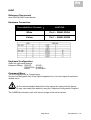
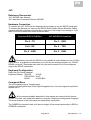
1
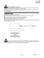
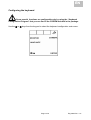
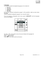
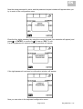
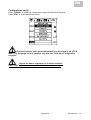
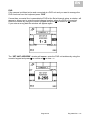
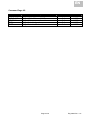
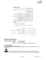
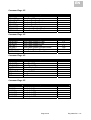
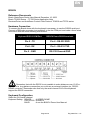
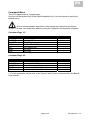
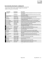
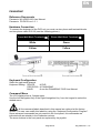
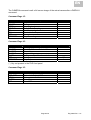
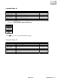
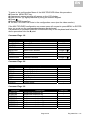
EN MULTIPROTOCOL KEYBOARD _____________________________________________________________ TSK1 USER MANUAL Before operating this unit, please read the instructions carefully to ensure the best possible performance. Page 1/78 Eng 0650 Rev. 1.01 EN BLANK PAGE Page 2/78 Eng 0650 Rev. 1.01 EN TSK1 Multi protocol Keyboard User Manual Contents Safety Rules ........................................................................................................................6 Contents of the package ......................................................................................................7 Keyboard top view ...............................................................................................................7 Keyboard rear view ..............................................................................................................8 Installing the keyboard .........................................................................................................9 Dip switch setup ...............................................................................................................9 Power supply connection ...............................................................................................10 Communications lines and connections.............................................................................11 RS485 Serial line connectors .........................................................................................11 RS232 Serial line connector ..............................................................................................12 Firmware Version...............................................................................................................13 Configuring the keyboard...................................................................................................14 Language .......................................................................................................................15 Password .......................................................................................................................16 Serial channels setup .....................................................................................................19 Devices selection........................................................................................................19 Protocols selection......................................................................................................21 Baudrate selection ......................................................................................................21 Configuration verify.....................................................................................................22 Utils Menu ......................................................................................................................23 Joystick.......................................................................................................................23 Contrast ......................................................................................................................24 Address ......................................................................................................................25 Reset ..........................................................................................................................25 Monitor setup .................................................................................................................26 Camera setup.................................................................................................................28 P/T ..............................................................................................................................29 DVR ............................................................................................................................30 MATRIX ......................................................................................................................32 MULTIPLEXER...........................................................................................................33 SPEED DOMES ................................................................................................................35 PELCO ...........................................................................................................................35 Reference Documents ................................................................................................35 Hardware Connection .................................................................................................35 Keyboard Configuration ..............................................................................................35 Command Menu .........................................................................................................35 PANASONIC ..................................................................................................................38 Reference Documents ................................................................................................38 Hardware Connection .................................................................................................38 Page 3/78 Eng 0650 Rev. 1.01 EN Keyboard Configuration ..............................................................................................39 Command Menu .........................................................................................................39 JVC ................................................................................................................................41 Reference Documents ................................................................................................41 Hardware Connection .................................................................................................41 Keyboard Configuration ..............................................................................................42 Command Menu .........................................................................................................42 SAMSUNG ELECTRONICS...........................................................................................44 Reference Documents ................................................................................................44 Hardware Connection .................................................................................................44 Keyboard Configuration ..............................................................................................44 Command Menu .........................................................................................................44 BOSCH ..........................................................................................................................46 Reference Documents ................................................................................................46 Hardware Connection .................................................................................................46 Keyboard Configuration ..............................................................................................46 Command Menu .........................................................................................................47 ENEO .............................................................................................................................50 Reference Documents ................................................................................................50 Hardware Connection .................................................................................................50 Keyboard Configuration ..............................................................................................50 Command Menu .........................................................................................................51 FASTRAX II....................................................................................................................52 Reference Documents ................................................................................................52 Hardware Connection .................................................................................................52 Keyboard Configuration ..............................................................................................52 Command Menu .........................................................................................................53 ELBEX EXC7000 ...........................................................................................................54 Reference Documents ................................................................................................54 Hardware Connection .................................................................................................54 Keyboard Configuration ..............................................................................................54 Command Menu .........................................................................................................54 DIGITAL VIDEO RECORDERS ........................................................................................57 ENEO .............................................................................................................................57 Reference Documents ................................................................................................57 Hardware Connection .................................................................................................57 Keyboard Configuration ..............................................................................................57 Command Menu .........................................................................................................57 SAMSUNG ELECTRONICS...........................................................................................59 Reference Documents ................................................................................................59 Hardware Connection .................................................................................................59 Keyboard Configuration ..............................................................................................59 Command Menu .........................................................................................................59 PANASONIC ..................................................................................................................62 Reference Documents ................................................................................................62 Hardware Connection .................................................................................................62 Keyboard Configuration ..............................................................................................62 Command Menu .........................................................................................................62 HUNT .............................................................................................................................64 Reference Documents ................................................................................................64 Hardware Connection .................................................................................................64 Page 4/78 Eng 0650 Rev. 1.01 EN Keyboard Configuration ..............................................................................................64 Command Menu .........................................................................................................64 JVC ................................................................................................................................66 Reference Documents ................................................................................................66 Hardware Connection .................................................................................................66 Keyboard Configuration ..............................................................................................66 Command Menu .........................................................................................................66 GANZ .............................................................................................................................68 Reference Documents ................................................................................................68 Hardware Connection .................................................................................................68 Keyboard Configuration ..............................................................................................69 Command Menu .........................................................................................................69 MATRIX .............................................................................................................................71 PELCO ASCII.................................................................................................................71 Reference Documents ................................................................................................71 Hardware Connection .................................................................................................71 Keyboard Configuration ..............................................................................................71 Command Menu .........................................................................................................71 ENEO .............................................................................................................................73 Reference Documents ................................................................................................73 Hardware Connection .................................................................................................73 Keyboard Configuration ..............................................................................................73 Command Menu .........................................................................................................73 MULTIPLEXER .................................................................................................................75 GE ..................................................................................................................................75 Reference Documents ................................................................................................75 Hardware Connection .................................................................................................75 Keyboard Configuration ..............................................................................................75 Command Menu .........................................................................................................75 SPECIFICATION ...............................................................................................................78 The manufacturer shall not be held responsible for any damages arising from improper use of the appliance described in this manual. Changes may be made to this manual without notice. Page 5/78 Eng 0650 Rev. 1.01 EN Safety Rules Before installing and using this product carefully read this manual and observe the following recommendations. ➊ The product complies with the regulations in force at the time this manual was issued concerning safety of electrical appliances, electromagnetic compatibility and general requirements. ➋ The unit must be installed by a qualified technician. ➌ The unit must be connected to a mains power supply that corresponds with the characteristics given in the Technical Specifications section. ➍ The product is designed for indoor applications and must not be installed outdoor or exposed to rain or moisture. ➎ Disconnect the power supply before carrying out any technical work or maintenance on the unit. ➏ Never open the unit. Tampering with the product shall invalidate the warranty. ➐ The unit should never be used in proximity to flammable substances or in potentially explosive atmospheres. ➑ The unit must be leant on a solid support. ➒ The unit may only be considered shutdown when the power cable and any cables connecting the unit to other appliances have been disconnected. ➓ All technical assistance must be provided solely by authorised technicians Keep this manual with care for future reference. The product and/or manual may use the following symbols: This symbol indicates that there are hazardous voltages, presenting a risk of electric shock, in the unit. This symbol indicates essential information for the installation, use and maintenance of the unit; particular attention should be paid when reading and carrying out these instructions. Page 6/78 Eng 0650 Rev. 1.01 EN Contents of the package When the product is delivered, make sure the package is intact and has no obvious signs of dropping scrapes or scratches. If the package is damaged contact the supplier immediately. ➊ TSK1 Keyboard ➋ Power Supply Unit ➌ Power Supply Cord ➍ Phone Cables RJ12 6P/6C PLUG-PLUG Inverted Wiring 1.5m (3 pcs) ➎ Phone wall block terminals RJ12 6P/6C (3 pcs) ➏ RS232 Serial Cable (Mouse Extender Cable) ➐ CDROM ➑ User Manual Keyboard top view Page 7/78 Eng 0650 Rev. 1.01 EN Keyboard rear view Page 8/78 Eng 0650 Rev. 1.01 EN Installing the keyboard Dip switch setup In the rear panel of the keyboard you find a 4 dip-switches (SW) used to insert/remove the load of the RS485 lines and lock the keyboard programming from the PC (see Figure 1). Figure 1 Move the load switch in ON position only for the devices connected at the RS485 line ends. All others devices connected to the RS485 line must have the load switch in OFF position (see the Figure 2 scheme ) Figure 2 Move DIP4 in ON position only for the firmware upgrade operations. During the normal use the DIP4 must be in OFF position . Page 9/78 Eng 0650 Rev. 1.01 EN Power supply connection Before connecting the power supply make sure the specifications for the keyboard power supply correspond to those for the system power supply. To supply the keyboard it is essential to use the power supply unit and cord provided with the keyboard itself. Using inappropriate and/or different equipment could expose personnel and the system to serious safety hazards. Procedure for power supply connection: ➊ Connect the power plug to the DC power jack in the rear of the keyboard. ➋ Connect the power supply cord to the power supply unit ➌ Connect the power supply cord plug to the wall outlet. ➍ The green LED on the power supply unit light on ➎ The keyboard LCD display lights on and shows an image; this means that the keyboard has been installed correctly. In order to save power and increase the LED lifetime, the display backlit switch off automatically after 5 minutes of inactivity. Simply moving the joystick or the jog-shuttle or pressing any key you will exit from the power saving mode. Page 10/78 Eng 0650 Rev. 1.01 EN Communications lines and connections RS485 Serial line connectors The connection between the keyboard and the various controlled devices is made using three RS485 half duplex serial channels via CH1-CH2-CH3 serial ports. If the controlled device doesn’t have an RS485 serial port it will be necessary to insert a signal converter (for example RS485-RS232 or RS485-Current Loop) between the keyboard and the device itself. We remember you that the RS485 maximum distance without repeater is almost 1200m (4000ft). Procedure for RS485 line connection: ➊ Connect the phone cable (supplied) to the desired RJ12 connector in the keyboard rear. ➋ Connect the other end of the phone cable (supplied) to the phone wall block terminals(supplied) ➌ Connect the RS485 line twisted pair cable to the phone wall block terminals following the Figure 3 scheme ➍ Connect the RS485 twisted pair cable end to the RS485 block terminals of the device (following the device instruction manual) TSK1 Keyboard Phone Wall Block Terminal TX/RX + White (Half Duplex RS485 Non Inverting) TX/RX (Half Duplex RS485 Inverting) Yellow Figure 3 Page 11/78 Eng 0650 Rev. 1.01 EN RS232 Serial line connector The CH2 can be also used to send/receive commands via RS232 serial port (COM connector). Use the Figure 4 to connect the keyboard with your device. Pin Signal Function 1 2 TX Transmitted data 3 RX Received data 4 DTR Data Terminal Ready 5 GND Ground 6 7 RTS Request To Send 8 9 Figure 4 Page 12/78 Eng 0650 Rev. 1.01 EN Firmware Version This manual is referred at the firmware version 1.01. To verify the firmware version installed in your keyboard follow this procedure. Use the Ⓔ or Ⓒ keys from the keypad to select the keyboard configuration main menu. Press at the same time the “LEFT NAVIGATION BUTTON” and the “RIGHT NAVIGATION BUTTON”; the firmware version information window will appear (also the firmware checksum is showed). Press Ⓒ to exit . Page 13/78 Eng 0650 Rev. 1.01 EN Configuring the keyboard Some special functions are configurable only by using the “Keyboard Configuration Program” that you can find in the CDROM included in the package. Use the Ⓔ or Ⓒ keys from the keypad to select the keyboard configuration main menu. Page 14/78 Eng 0650 Rev. 1.01 EN Language Is it possible to select the keyboard language in a five choice list: ENGLISH ITALIANO FRANÇAIS ESPAÑOL DEUTSCH By using the “Keyboard configuration program” will be possible to add an extra custom language. See the “Keyboard configuration program” user manual for detail. From the keyboard configuration main menu press “LANGUAGE” and the languages choice list will appear: Use “▲” or “▼” or the joystick to move the cursor between the languages list. Select the right language. Press “ ” when done. Press “ESC” if you want to exit from this menu. Page 15/78 Eng 0650 Rev. 1.01 EN Password Use the Ⓔ or Ⓒ keys from the keypad to select the keyboard configuration main menu. Keyboard security is managed by three password levels: ➊ Connection password: requested when the keyboard is switched on; it is used to prevent improper use of the keyboard by unauthorised personnel. Is it possible to configure this password only by using the “Keyboard Configuration Program”. ➋ Setup password: requested to manage the configuration of the keyboard. Is it possible to configure this password directly by the keyboard or by using the “Keyboard Configuration Program”. ➌ Reset alarm password: requested when an alarm has to be cleared. Is it possible to configure this password only by using the “Keyboard Configuration Program”. Passwords are defined at the individual keyboard level. They can be disabled (default status, when leaving the factory). >> Page 16/78 Eng 0650 Rev. 1.01 EN Press to enter in the setup password configuration menu. Press “ESC” if you want to exit from this menu. Press “NO” if you want to disable the password. Press “YES” if you want to active or modify the setup password; the following menu will appear: Enter the four (4) digits password from the numeric keypad and press Ⓔ or “ENTER” to confirm or Ⓒ to clear or “ESC” to exit and disable password. The password confirmation window will appear for few seconds. >> Page 17/78 Eng 0650 Rev. 1.01 EN Now the setup password is active and the password request window will appear when you try to enter in the configuration menu: Enter the four digits password by using the numeric keypad (four asterisks will appear) and press Ⓔ or “ENTER” to confirm or Ⓒ to clear or “ESC” to exit. If a wrong password is entered a warning window will appear: If the right password is entered a confirmation window will appear: Now you can enter in the keyboard configuration menu. Page 18/78 Eng 0650 Rev. 1.01 EN Serial channels setup Devices selection Before to use the keyboard is necessary to configure the system layout. The first step to do this is to configure the devices connected at the three serial lines of the keyboard. From the keyboard configuration main menu press “ENTER” to move in the serial channels menu. >> Use the Ⓔ key or the Ⓒ key to move right or left the active serial channel. Select the serial channel that you want to configure. Page 19/78 Eng 0650 Rev. 1.01 EN Press “DEVICE” to activate the device selection list. Use “▲” or “▼” or the joystick to move the cursor between the device list. Select the right device. Select “NULL” if you don’t have any device connected to this serial channel. Press when done. For example select “SPEED DOME”. It’s not possible to mix different kind of devices in the same serial line, also if there are products of the same manufacturer or with the same protocol. Every single serial line must be associated at only one kind of device. The serial channel label symbol change when you select a device according with this symbols: SPEED DOME DVR MATRIX MUX Page 20/78 MUX Eng 0650 Rev. 1.01 EN Protocols selection Press “PROTOCOLS” to activate the protocols selection list. Use “▲” or “▼” or the joystick to move the cursor between the device list. Select the right protocol. Press when done. For example select “PELCO-D”. Baudrate selection Press “BAUD” to activate the baud rate selection list. Use “▲” or “▼” or the joystick to move the cursor between the device list. Select the right baud rate. Press when done. For example select “9600BPs”. Page 21/78 Eng 0650 Rev. 1.01 EN Configuration verify Press “VISUAL” to show the configuration report for this serial channel. Press “ESC” to come back when done. Keyboard address and contrast adjustment are described in the UTILS menu. The language setup is possible only with the “Keyboard Configuration Program”. Repeat the above sequence for all serial channels. Press “ESC” when done to come back at the previous menu. Page 22/78 Eng 0650 Rev. 1.01 EN Utils Menu Use the Ⓔ or Ⓒ keys from the keypad to select the “UTILS” menu. Joystick Joystick calibration is process which allows correct operation of the device. Normally it is only done at the production stage and recalibration by the operator should never be necessary. If the joystick behaves incorrectly (if, for example, a pan or tilt direction stays active when the joystick is at rest) it may be necessary to carry out the calibration procedure. Press “JOYSTICK” to move in the joystick calibration menu. The following menu will appear: Press “ESC” if you want to exit without continuing with calibration. Move the joystick left until the number showed still fixed; press push-buttons on top of the joystick when done. Move the joystick right until the number showed still fixed; press push-buttons on top of the joystick when done. Move the joystick down until the number showed still fixed; press push-buttons on top of the joystick when done. >> Page 23/78 or one of the two or one of the two or one of the two Eng 0650 Rev. 1.01 EN Move the joystick up until the number showed still fixed; press push-buttons on top of the joystick when done. or one of the two Move the joystick zoom axis clockwise until the number showed still fixed; press one of the two push-buttons on top of the joystick when done. or Move the joystick zoom axis counter clockwise until the number showed still fixed; press or one of the two push-buttons on top of the joystick when done. Contrast This menu allows to calibrate the contrast of the LCD display in the 64 steps (0-63). Press “CONTRAST” to move in the the contrast calibration menu. The following menu will appear: Use “▲” or “▼” or the joystick to increase/decrease the contrast value in the range 0-63. Press to confirm and save the new contrast value or “ESC” to exit without save. Page 24/78 Eng 0650 Rev. 1.01 EN Address This menu allows to assign the system identification number of keyboard. Each keyboard in the system should be identified by a different number; the presence of more than one keyboard with the same number could cause communication problems. The keyboard address must be in the range 0-255. Press “ADDRESS” to move in the the keyboard address menu. The following menu will appear: Select the keyboard address (ex.: n.1) from the numeric keypad and press Ⓔ to confirm or Ⓒ to clear. If you enter a wrong data the window will appear again. Reset Resets factory default values. The reset operation should be confirmed by the operator. Press to confirm or “ESC” to exit without reset the keyboard. Page 25/78 Eng 0650 Rev. 1.01 EN Monitor setup Whit this menu you can define the connected monitors list that you want to manage from this keyboard. From the configuration menu press the “MONITOR” key; the following menu appear: Select the monitor number (for example.: n.1) from the numeric keypad and press Ⓔ to confirm or Ⓒ to clear. >> Page 26/78 Eng 0650 Rev. 1.01 EN Press “ACTIVE” if you want to manage this monitor from the keyboard. Press “DISABLED” if you doesn’t want to manage this monitor from the keyboard. Repeat the above sequence for all monitors. Press “ESC” when done to come back at the previous menu Page 27/78 Eng 0650 Rev. 1.01 EN Camera setup Whit this menu you can define how the cameras are connected with the system devices . Press the “CAMERA” key; the following menu will appear: Select the camera number (ex.: n.1) from the numeric keypad and press Ⓔ to confirm or Ⓒ to clear. Press “ACTIVE” if you want to manage this camera from the keyboard. Press “DISABLED” if you doesn’t want to manage this camera from the keyboard. IF THE CAMERA IS DEFINED DISABLED THE “P/T”, “DVR”, “MATRIX”, “MUX” KEYS ARE NOT ACTIVE. Page 28/78 Eng 0650 Rev. 1.01 EN P/T If the camera is defined active and it’s a speed dome or P&T unit and you want to manage the telemetry function from the keyboard press “P/T”. The “ACTIVATE P/T” window will appear; move the joystick until “ACTIVE” is highlighted and press Ⓔ from the numeric keypad. If more than one serial line is associated at SPEED DOME in the Serial channel setup, a window will appear to allows you to enter the serial channel number where the P/T is connected. Enter the number by using the numeric keypad and press Ⓔ to confirm or Ⓒ to clear. If you enter a wrong data the window will appear again. If the camera is defined active and is a speed dome or P&T unit but you doesn’t want to manage the telemetry function from the keyboard press “P/T”. The “ACTIVATE P/T” window will appear; move the joystick until “DISABLED” is highlighted and press Ⓔ from the numeric keypad. Page 29/78 Eng 0650 Rev. 1.01 EN DVR If the camera is defined active and connected at a DVR unit and you want to manage the DVR functions from the keyboard press “DVR”. If more than one serial line is associated at DVR in the Serial channel setup, a window will appear to allows you to enter the serial channel number where the DVR is connected. Enter the number by using the numeric keypad and press Ⓔ to confirm or Ⓒ to clear. If you enter a wrong data the window will appear again. The “SET UNIT ADDRESS” window will appear; enter the DVR unit address by using the numeric keypad and press Ⓔ to confirm or Ⓒ to clear. >> Page 30/78 Eng 0650 Rev. 1.01 EN The “SELECT INPUT” window will appear: Enter the video input number of the DVR where the camera is connected by using the numeric keypad and press Ⓔ to confirm or Ⓒ to clear. Page 31/78 Eng 0650 Rev. 1.01 EN MATRIX If the camera is defined active and connected at a video MATRIX unit and you want to manage the MATRIX functions from the keyboard press “MATRIX”. The “SELECT INPUT” windows will appear; enter the MATRIX video input by using the numeric keypad and press Ⓔ to confirm or Ⓒ to clear. Page 32/78 Eng 0650 Rev. 1.01 EN MULTIPLEXER If the camera is defined active and connected at a video MULTIPLEXER unit and you want to manage the MULTIPLEXER functions from the keyboard press “MUX”. If more than one serial line is associated at MUX in the Serial channel setup, a window will appear to allows you to enter the serial channel number where the MUX is connected. Enter the number by using the numeric keypad and press Ⓔ to confirm or Ⓒ to clear. If you enter a wrong data the window will appear again. The “SET UNIT ADDRESS” window will appear; enter the MUX unit address by using the numeric keypad and press Ⓔ to confirm or Ⓒ to clear. >> Page 33/78 Eng 0650 Rev. 1.01 EN The “SELECT INPUT” window will appear: Enter the video input number of the MUX where the camera is connected by using the numeric keypad and press Ⓔ to confirm or Ⓒ to clear. Press ” ESC” when done to come back to the previous menu. Page 34/78 Eng 0650 Rev. 1.01 EN SPEED DOMES PELCO Reference Documents Pelco D Protocol Version 2 Revision 1 August 15, 2003 Hardware Connection Phone Wall Block Terminals PELCO Dome White RX + Yellow RX - Keyboard Configuration Select the right serial channel Keyboard Setting: DEVICE PROTOCOL BAUD SPEED DOME PELCO see the PELCO Dome User Manual Command Menu The LCD display show a 6 pages menu. Use the Left Navigation Key or the Right Navigation Key from the keypad to select the wished menu. All the command labels described in this manual are referred at the factory version. The user can modify this labels by using the “Keyboard Configuration Program”. Command Page 1/6 Command IRIS+ IRISCAMERAON CAMERAOFF SPRESET CPRESET GPRESET FLIP180 Description Iris Open Iris Close Switch Camera ON Switch Camera OFF Set Preset Position Clear Preset Position Go to Preset Position Flip 180° Page 35/78 Parameter1 1-32 1-32 1-32 - Parameter2 - Eng 0650 Rev. 1.01 EN Command Page 2/6 Command GOTO0PAN SETAUX CLEARAUX RESET ZONESTART ZONEEND CSCREEN ALARMACK Description Goto Home Pan Position Set Auxiliary Clear Auxiliary Remote Reset Set Start Zone Set End Zone Clear Screen Alarm Acknowledge Parameter1 1-8 1-8 1-8 1-8 1-8 Parameter2 - Parameter1 0-3 0-3 - Parameter2 - Parameter1 0-255 Parameter2 Parameter1 0-1 - Parameter2 0-255 - Command Page 3/6 Command ZONSCAN+ ZONSCANSETPSTART SETPSTOP RUNPATT ZOOMSPPED FOCUSSP RCAMERA Description Zone Scan ON Zone Scan OFF Set Start Pattern Set Stop Pattern Run Pattern Zoom Speed Focus Speed Reset Camera to Defaults Command Page 4/6 Command AFOCUSA AFOCUS+ AFOCUSDELAYMOD AIRISAUTO AIRISON AIRISOFF SHT-SPEED Description Auto Focus AUTO Auto Focus ON Auto Focus OFF Enable Device Phase Delay Mode Auto Iris AUTO Auto Iris ON Auto Iris OFF Shutter Speed 0-255 Command Page 5/6 Command AGCAUTO AGCON AGCOFF LCKPHDLY BCKON BCKOFF AWBLCON AWBLCOFF Description AGC AUTO AGC ON AGC OFF Adjust Line Lock Phase Delay Backlight Compensation ON Backlight Compensation OFF AUTO White Balance ON AUTO White Balance OFF Page 36/78 Eng 0650 Rev. 1.01 EN Command Page 6/6 Command W-BLC-R-B W-BLC-M-G ADJGAIN IRISL IRISP Description Adjust White Balance (R-B) Adjust White Balance (M-G) Adjust Gain Adjust Auto Iris Level Adjust Auto Iris Peak value Page 37/78 Parameter1 0-1 0-1 0-1 0-1 0-1 Parameter2 0-255 0-255 0-255 0-255 0-255 Eng 0650 Rev. 1.01 EN PANASONIC Reference Documents Panasonic WV-CS950 Dome User Manual PanasonicWV-CS850 Dome User Manual Panasonic WV-CS960 Dome User Manual Protocol Information WV-CS860 Panasonic V 3.1 July 2002 Hardware Connection To connect the keyboard to the Speed Dome unit you must use two phone wall terminal blocks and one phone cable RJ12 6/6. Connect the “Data Port” RJ connector to the phone wall terminal block ②. Connect the phone wall terminal block ② to the phone wall terminal block ① by using two wires (see the following table). Phone Wall Block Terminals ① Phone Wall Block Terminals ② White Green Yellow Yellow Connect the desired serial line connector of the keyboard with the phone wall terminal block ① by using the phone cable RJ12 6/6. Page 38/78 Eng 0650 Rev. 1.01 EN Keyboard Configuration Select the right serial channel Keyboard Setting: DEVICE PROTOCOL BAUD SPEED DOME PANASONIC see the PANASONIC Dome User Manual Command Menu The LCD display show a 4 pages menu. Use the Left Navigation Key or the Right Navigation Key from the keypad to select the wished menu. All the command labels descried in this manual are referred at the factory version. The user can modify this labels by using the “Keyboard Configuration Program”. Page 39/78 Eng 0650 Rev. 1.01 EN Command Page 1/4 Command APANON APANOFF APANI RESET APANeOFF APANeON FLIPON FLIPOFF Description Auto Pan ON Auto Pan OFF Auto Pan Sweep Area Inverse Reset Auto Pan Endless OFF Auto Pan Endless ON Digital Flip ON Digital Flip OFF Parameter - Command Page 2/4 Command HOME GPRESET SPRESET 180DT PATTSTART PATTSTOP PATTSET Description Go to Home Position Go to Preset Position Set Preset Position 180 Degree Turn Pattern Start Pattern Stop Pattern Set Parameter 0-64 0-64 - Command Page 3/4 Command MENUON MENUOFF SET ESC IRIS+ IRISALCON AFOCUS Description Set Menu ON Set Menu OFF Setup Menu SET1 Setup Menu SET2 Iris Open Iris Close ALC ON One Shot Auto Focus ON Parameter - Command Page 4/4 Command AL1OFF AL2OFF AL3OFF AL4OFF AUX1ON AUX1OFF AUX2ON AUX2OFF Description Alarm 1 OFF Alarm 2 OFF Alarm 3 OFF Alarm 4 OFF Auxiliary 1 ON Auxiliary 1 OFF Auxiliary 2 ON Auxiliary 2 OFF Page 40/78 Parameter - Eng 0650 Rev. 1.01 EN JVC Reference Documents JVC Dome TK-C655E, TK-C676E User Manual JVC Protocol Version 1.02, April 2003 Hardware Connection Phone Wall Block Terminals JVC Dome White Ⓒ Yellow Ⓓ See the “Connections & Installation” section on the speed dome Instrucions Manual. Page 41/78 Eng 0650 Rev. 1.01 EN Be sure to set properly the Switch 4 (Multi drop or Point to Point connection) Set ON the Switch 5 (Simplex) Be sure to set properly the Switch 8 (RX Termination) Keyboard Configuration Select the right serial channel Keyboard Setting: DEVICE PROTOCOL BAUD SPEED DOME JVC 9600BPs Command Menu The LCD display show a 5 pages menu. Use the Left Navigation Key or the Right Navigation Key from the keypad to select the wished menu. All the command labels described in this manual are referred at the factory version. The user can modify this labels by using the “Keyboard Configuration Program”. Command Page 1/5 Command HOMESET HOMECLR HOMEGO SPRESET CPRESET GPRESET Description Set Home Position Clear Home Position Go to Home Position Set Preset Position Clear Preset Position Go to Preset Position Page 42/78 Parameter 1-99 1-99 1-99 Eng 0650 Rev. 1.01 EN Command Page 2/5 Command APANON APANOFF APANSTART APANEND APANDIR APANVSET GOTOA-PS GOTOA-PE Description Auto Pan ON Auto Pan OFF Set Auto Pan Start Position Set Auto Pan End Position Set Auto Pan Direction Set Auto Pan Velocity Go to Auto Pan Start Position Go to Auto Pan End Position Parameter - Command Page 3/5 Command PATSTART PATSTOP PATTSET PATNSET PATPOS PATDWSET Description Auto Patrol Pattern START Auto Patrol Pattern STOP Auto Patrol Pattern Set Auto Patrol Pattern Number Select Auto Patrol Pattern Position Auto Patrol Pattern Dwell Set Parameter 1-3 1-3 1-99 1-99 - Command Page 4/5 Command AFLIPON AFLIPOFF AFLIPAUTO ALARMACK MENU MENU-ENT IRIS+ IRIS- Description Auto Flip ON Auto Flip OFF Auto Flip AUTO Alarm Display Set Menu Menu ENTER Iris Open Iris Close Parameter - Command Page 5/5 Command AUX1ON AUX2ON AUX3ON AUX1OFF AUX2OFF AUX3OFF Description Auxiliary 1 ON Auxiliary 2 ON Auxiliary 3 ON Auxiliary 1 OFF Auxiliary 2 OFF Auxiliary 3 OFF Page 43/78 Parameter - Eng 0650 Rev. 1.01 EN SAMSUNG ELECTRONICS Reference Documents Samsung Dome VSCC-C6405P User Manual Samsung Protocol Version 2.2, July 20, 2005 Hardware Connection Phone Wall Block Terminals SAMSUNG Dome White RX + Yellow RX - Keyboard Configuration Select the right serial channel Keyboard Setting: DEVICE PROTOCOL BAUD SPEED DOME SAMSUNG see the SAMSUNG Dome User Manual Command Menu The LCD display show a 3 pages menu. Use the Left Navigation Key or the Right Navigation Key from the keypad to select the wished menu. All the command labels described in this manual are referred at the factory version. The user can modify this labels by using the “Keyboard Configuration Program”. Command Page 1/3 Command NUMBERKEY ZONSCAN+ ZONSCANCAMERAON MENUON MENUOFF MENU-ENT RESET Description Numeric Key Scan START Scan STOP Camera ON Menu ON Menu OFF Menu ENTER Factory Reset Parameter * 1-4 1-4 - * For the use of the Numeric Key refer to the Samsung User Manual Page 44/78 Eng 0650 Rev. 1.01 EN Command Page 2/3 Command GPRESET SPRESET CPRESET APANON APANOFF PATTSTART PATTSTOP AFOCUS Description Go to Preset Position Set Preset Position Clear Preset Position Auto Pan ON Auto Pan OFF Pattern START Pattern STOP Auto Focus Parameter 0-127 0-127 0-127 1-3 1-3 - Command Page 3/3 Command IRIS+ IRIS- Description Iris Open Iris Close Page 45/78 Parameter - Eng 0650 Rev. 1.01 EN BOSCH Reference Documents Bosch BasicDome Series User Manual December 10, 2003 Bosch TC8560 Series - TC700 Series Application Note Receiver/Driver and AutoDome Control Code Protocol TC8560 and TC700 series Hardware Connection To connect the Bosch dome with the keyboard is necessary to use the RS232 serial port. Connect a DB9 male connector (not supplied) to the the COM port and make a three wires connection with the dome following this scheme: Keyboard RS232 COM Port BOSCH Dome RS232 terminals Pin 2 - TX Pin 6 - RS-232 RXD Pin3 - RX Pin 5 - RS-232 TXD Pin 5 - GND RS-232 Ground GND Remember that with the RS232 is not possible to make distances over 15-25 m. If you need a long distance connection you must use an external interface (ex. RS232RS485 converter). Remember also that only the serial channel CH2 of the keyboard support the RS232 connection. Keyboard Configuration Select the CH2 serial channel Keyboard Setting: DEVICE PROTOCOL BAUD SPEED DOME BOSCH see the BOSCH Dome User Manual Page 46/78 Eng 0650 Rev. 1.01 EN Command Menu The LCD display show a 2 pages menu. Use the Left Navigation Key or the Right Navigation Key from the keypad to select the wished menu. All the command labels described in this manual are referred at the factory version. The user can modify this labels by using the “Keyboard Configuration Program”. Command Page 1/2 Command AUXON AUXOFF AUXTOG SHOT SET IRIS+ IRIS- Description Auxiliary ON Auxiliary OFF AUX Toggle Pre Position SHOW Pre Position SET Iris Open Iris Close Parameter * * * * * - Command Page 2/2 Command AUXLTCH+ AUXLTCHAUXLTCHC IRISB IRISD Description Latching AUX ON Latching AUX OFF Cancel Latching AUX Iris Brighter (Variable Speed Lens) Iris Darker (Variable Speed Lens) Parameter * * - (*) For the parameter values refer to the Figure 5 and Figure 6 extracted from the Bosch User manual. Page 47/78 Eng 0650 Rev. 1.01 EN Figure 5 Page 48/78 Eng 0650 Rev. 1.01 EN Figure 6 Page 49/78 Eng 0650 Rev. 1.01 EN ENEO Reference Documents ENEO Dome VSCC-C6405P User Manual ENEO Protocol Version 1.17 Hardware Connection Phone Wall Block Terminals ENEO Dome RX+ RS485 Half Duplex Mode RX- RS485 H Half Duplex Mode White Yellow Keyboard Configuration Select the right serial channel Keyboard Setting: DEVICE PROTOCOL BAUD SPEED DOME ENEO see the ENEO Dome User Manual Page 50/78 Eng 0650 Rev. 1.01 EN Command Menu The LCD display show a 3 pages menu. Use the Left Navigation Key or the Right Navigation Key from the keypad to select the wished menu. All the command labels described in this manual are referred at the factory version. The user can modify this labels by using the “Keyboard Configuration Program”. Command Page 1/3 Command RUNPATT PATTSAVE MENU-PT HOMEGO AUTOSCAN MENU-AS CTRL Description Run Pattern Pattern Record Menu Pattern Run Home Run Autoscan Menu Autoscan Turbo ON/OFF Parameter 1-255 1-255 - Command Page 2/3 Command MENU ENTER ESC MENU-AL SPRESET CPRESET GPRESET MENU-PS Description Dome Menu ENTER Command ESC Command Alarm Menu Set Preset Position Clear Preset Position Go to Preset Position Menu Preset Parameter 1-255 1-255 1-255 - Command Page 3/3 Command IRIS+ IRISTOUR MENU-TR OFF ON Description Iris Open Iris Close Run Tour Menu tour ON Command OFF Command Page 51/78 Parameter 1-255 1-255 1-255 Eng 0650 Rev. 1.01 EN FASTRAX II Reference Documents Fastrax II Dome VSCC-C6405P User Manual Fastrax II Protocol Version 1.17 Hardware Connection Phone Wall Block Terminals FASTRAX II Dome RX+ RS485 Half Duplex Mode RX- RS485 half Duplex Mode White Yellow Keyboard Configuration Select the right serial channel Keyboard Setting: DEVICE PROTOCOL BAUD SPEED DOME FASTRAX II see the FASTRAX II Dome User Manual Page 52/78 Eng 0650 Rev. 1.01 EN Command Menu The LCD display show a 3 pages menu. Use the Left Navigation Key or the Right Navigation Key from the keypad to select the wished menu. All the command labels described in this manual are referred at the factory version. The user can modify this labels by using the “Keyboard Configuration Program”. Command Page 1/3 Command RUNPATT PATTSAVE MENU-PT HOMEGO AUTOSCAN MENU-AS CTRL Description Run Pattern Pattern Record Menu Pattern Run Home Run Autoscan Menu Autoscan Turbo ON/OFF Parameter 1-255 1-255 - Command Page 2/3 Command MENU ENTER ESC MENU-AL SPRESET CPRESET GPRESET MENU-PS Description Dome Menu ENTER Command ESC Command Alarm Menu Set Preset Position Clear Preset Position Go to Preset Position Menu Preset Parameter 1-255 1-255 1-255 - Command Page 3/3 Command IRIS+ IRISTOUR MENU-TR OFF ON Description Iris Open Iris Close Run Tour Menu tour ON Command OFF Command Page 53/78 Parameter 1-255 1-255 1-255 Eng 0650 Rev. 1.01 EN ELBEX EXC7000 Reference Documents Camera ID Code Manual For Digital Camera Control (protocol description) Command Manula For Digital Camera Control ( protocol description) EXC7000 Command Table1(command list) Instant Dome Camera Manual Istructions (istructions installation instant dome) The keyboard can control only the instant dome series EXC7000. Other series are not supported. Hardware connection Phone Wall Block Terminals ELBEX Dome White RS422+ Yellow RS422- Keyboard configuration Select the right serial channel Keyboard Setting: DEVICE > SPEED DOME PROTOCOL >ELBEX BAUD > 4800 Bps (fixed for instant dome,see reference document) Command Menu The LCD display show a 5 pages menu. Use the Left Navigation Key or the Right Navigation Key from the keypad to select the wished menu. All the command labels described in this manual are referred at the factory version. The user can modify this labels by using the “Keyboard Configuration Program”. Control that dip switch present on the dome are set in correspondence at camera number set on the keyboard.See manual instruction dome for details. * Command IRIS+ and IRIS- not work on the dome with auto iris totally automatic. See manual instruction dome for details. Page 54/78 Eng 0650 Rev. 1.01 EN Command Page 1/5 Command A PAN ON A PAN OFF A PAN LEFT A PAN RIGHT SCAN ON SCAN OFF S PRESET G PRESET Description Active function auto pan Disable function auto pan Active function auto pan,anti-clockwise Active function auto pan,clockwise Active function scansion preset positions Disable function scansion preset positions Define Preset Position Go to the Preset Position Parameter 1-99 1-99 Command Page 2/5 Command AL SCAN ON AL SCAN OFF SET AL POS GO AL POS D ZOOM ON D ZOOM OFF A FOCUS+ A FOCUS- Description Active function scansion alarm positions Disable function scansione alarm positions Define Alarm Position Go to the Alarm Position Active zoom digital/automatic Disable zoom digital/automatic Active auto focus Disable auto focus Parameter 1-99 1-99 - Command Page 3/5 Command A IRIS ON A IRIS OFF IRIS+ IRISSHUTT.ON SHUTT.OFF A SHUTTER Description Active iris digital/automatic Disabile iris digital/automatic Iris Open* Iris Close* Shutter on,active Shutter off,disable Active auto shutter Page 55/78 Parameter - Eng 0650 Rev. 1.01 EN Command Page 4/5 Command WIPER START WIPER STOP S AL POS ALL C AL POS MOVE AL POS LAST AL POS AL POS TIME AL POS V Description Active function wiper Disable function wiper Set all Alarm Positions as actives in the scansion list of Alarm position Clear the selected Alarm Position from the scansion list of Alarm position Set the Alarm position as active in the scansion list of Alarm position Go to the last Alarm Position enabled, before start Alarm position scan Setting the time of permanence on a singol Alarm position during scan Setting the velocity of attainment for a singol Alarm position during scan Parameter 1-99 1-99 1-99 1-8 Command Page 5/5 Command AUX ON AUX OFF S ALL POS CLEAR POS MOVE POS LAST POS POS TIME POS V Description Active Auxiliary Disable Auxiliary Set all Preset Positions as actives in the scansion list of Preset position Clear the selected Preset Position from the scansion list of Preset position Set the Preset position as active in the scansion list of Preset position Go to the last Preset Position enabled, before start Preset position scan Setting the time of permanence on a singol Preset position during scan Setting the velocity of attainment for a singol Preset position during scan Page 56/78 Parameter 1-8 1-8 1-99 1-99 1-99 1-8 Eng 0650 Rev. 1.01 EN DIGITAL VIDEO RECORDERS ENEO Reference Documents Eneo DVR DLR2-04N, DLR2-09N, DLR2-16N User Manual Eneo DVR Protocol Ver. 1.5 Hardware Connection Phone Wall Block Terminals ENEO DVR White RX+ Yellow RX- Keyboard Configuration Select the right serial channel Keyboard Setting: DEVICE PROTOCOL BAUD DVR ENEO see the ENEO DVR User Manual Command Menu The LCD display show a 3 pages menu. Use the Left Navigation Key or the Right Navigation Key from the keypad to select the wished menu. All the command labels described in this manual are referred at the factory version. The user can modify this labels by using the “Keyboard Configuration Program”. The factory menu command labels are copy of those presents in the DVR front panel; for the functions associated at this labels refer to the DVR User Manual. The arrow buttons in the front panel are replaced by the joystick. The only exceptions are for the MENU and CAMERA commands. Page 57/78 Eng 0650 Rev. 1.01 EN To enter in the configuration Menu of the DVR follow this procedure: ➊ Press the MENU-ENT key. ➋ A password request window will appear on the LCD display. ➌ Enter the four (4) digits password by using the numeric keypad. ➍ Press Ⓔ. ➎The DVR will enter in the configuration menu (see the video monitor). If the DVR configuration on screen menu will request to press MENU or ENTER keys you must use the correspondent keys on the keyboard. If a password is requested press the PASSWORD key on the keyboard and follow the above procedure from the ➌ point. The CAMERA command recall a full screen image of the actual camera after a DISPLAY command. Command Page 1/3 Command PLAY PAUSE STOP SEARCH FF RW REC SPOT Description Parameter - Description Parameter - Command MENU-ENT Description Menu Enter Window Parameter MENU Menu - ENTER Enter - PASSWORD Password window Playback Pause Stop Search Fast Forward Rewind Record Spot Command Page 2/3 Command DISPLAY SEQ FREEZE COUNTER CAMERA ALARM PTZ Display Sequence Freeze Counter Camera Alarm PTZ Command Page 3/3 4 digits + Ⓔ 4 digits + Ⓔ Page 58/78 Eng 0650 Rev. 1.01 EN SAMSUNG ELECTRONICS Reference Documents Samsung Electronics DVR SHR2160-N User Manual Samsung Electronics DVR Protocol Ver. 2.0 Hardware Connection Phone Wall Block Terminals SAMSUNG ELECTRONICS DVR White RX+ Yellow RX- Keyboard Configuration Select the right serial channel Keyboard Setting: DEVICE PROTOCOL BAUD DVR SAMSUNG EL. see the SAMSUNG EL. DVR User Manual Command Menu The LCD display show a 3 pages menu. Use the Left Navigation Key or the Right Navigation Key from the keypad to select the wished menu. All the command labels described in this manual are referred at the factory version. The user can modify this labels by using the “Keyboard Configuration Program”. The factory menu command labels are copy of those presents in the DVR front panel; for the functions associated at this labels refer to the DVR User Manual. Page 59/78 Eng 0650 Rev. 1.01 EN Some advanced command are not present in the front panel; this commands are indicated with an asterisk in the Parameter column. The arrow buttons in the front panel are replaced by the joystick. The only exceptions are for the MENU and CAMERA commands. To enter in the configuration Menu of the DVR follow this procedure: ➊ Press the MENU-ENT key. ➋ A password request window will appear on the LCD display. ➌ Enter the four (4) digits password by using the numeric keypad. ➍ Press Ⓔ. ➎The DVR will enter in the configuration menu (see the video monitor). If the DVR configuration on screen menu will request to press MENU or ENTER keys you must use the correspondent keys on the keyboard. If a password is requested press the PASSWORD key on the keyboard and follow the above procedure from the ➌ point. The CAMERA command recall a full screen image of the actual camera after a DISPLAY command. Command Page 1/3 Command PLAY STOP SEARCH FF RW REC RECLOCK FREEZE Description Playback Stop Search Fast Forward Rewind Record Lock the REC key Freeze Parameter - Command Page 2/3 Command DISPLAY SEQ CAMERA ALARM EJECT PANIC MODE EVENT Description Select Split Screen in DisplayMode Start Auto Sequence Mode Recall Full Screen Selected Camera Recall Alarm Mode Eject Start Real Time Recording Mode Key Event Search Parameter * * ** * (*) Key not present in the DVR front panel (**) Only for DVR models with DVD recoder Page 60/78 Eng 0650 Rev. 1.01 EN Command Page 3/3 Command AUDIO Description Audio ON/OFF Parameter - ZOOMAREA Active Digital Zoom - MENU-ENT Menu Enter Window 4 digits + Ⓔ MENU Menu - ENTER Enter - PASSWORD Password window 4 digits + Ⓔ Page 61/78 Eng 0650 Rev. 1.01 EN PANASONIC Reference Documents Panasonic WJ-HD220/160 User Manual Panasonic PS-DATA ver 1.0.1 Hardware Connection). To connect the keyboard to the DVR unit you must use two phone wall teminals blocks and two phone cable R12 6/6 (see the following picture): Phone Wall Block Terminals ① Phone Wall Block Terminals ② White Green Yellow Yellow Keyboard Configuration Select the right serial channel Keyboard Setting: DEVICE PROTOCOL BAUD DVR PANASONIC see the PANASONIC DVR User Manual Command Menu The LCD display show a 3 pages menu. Use the Left Navigation Key or the Right Navigation Key from the keypad to select the wished menu. All the command labels described in this manual are referred at the factory version. The user can modify this labels by using the “Keyboard Configuration Program”. Some advanced commands are not present in the front panel; this commands are indicated with an asterisk in the Parameter column. The arrow buttons in the front panel are replaced by the joystick. Page 62/78 Eng 0650 Rev. 1.01 EN The CAMERA command recall a full screen image of the actual camera after a DISPLAY command. Command Page 1/3 Command PLAY PAUSE STOP SEARCH FF RW REC STOPREC Description Playback Pause Stop Playback Time & Date Search Fast Forward to the End Rewind to the Top Record Stop Recording Parameter - Command Page 2/3 Command DISPLAY CAMERA ALMRST ALMSUS MULTI SEQ SEQSTOP Description Multiscreen Select Recall Full Screen Selected Camera Reset Alarm Suspend Alarm Multiscreen/Spot Monitor selection Start Sequence Stop Sequence Parameter 1-99 * (*) Key not present in the DVR front panel Command Page 3/3 Command OSD-ON OSD-OFF MENU ENTER ESC Description Status Info Display ON Status Info Display OFF Menu Menu Enter Menu ESC Page 63/78 Parameter - Eng 0650 Rev. 1.01 EN HUNT Reference Documents Hunt HDR-08/16MS User Manual Hardware Connection Phone Wall Block Terminals HUNT DVR White Pin 6 – RS485 RXDA Yellow Pin 7 – RS485 RXDB Keyboard Configuration Select the right serial channel Keyboard Setting: DEVICE PROTOCOL BAUD DVR HUNT 9600 BPs Command Menu The LCD display show a 2 pages menu. Use the Left Navigation Key or the Right Navigation Key from the keypad to select the wished menu. All the command labels described in this manual are referred at the factory version. The user can modify this labels by using the “Keyboard Configuration Program”. The CAMERA command recall a full screen image of the actual camera. Page 64/78 Eng 0650 Rev. 1.01 EN Command Page 1/2 Command RW FIELDRW FASTRW SCREEN FIELDFW FASTFW PLAY STOP Description Rewind Field Rewind Fast Rewind Select Screen Camera Formats Field Forward Fast Forward Playback Stop Playback Parameter - Command Page 2/2 Command SEL AUTO MENU-ENT CAMERA Description Select Screen Format Start Auto Sequence Menu Recall Full Screen Selected Camera Page 65/78 Parameter - Eng 0650 Rev. 1.01 EN JVC Reference Documents JVC VR509E User Manual JVC Operation Command Protocol VR509E Hardware Connection To connect the JVC DVR with the keyboard is necessary to use the RS232 serial port. To connect the devices you can use the RS232 Serial Cable (Mouse Extender Cable) supplied with the keyboard or build or buy a new one if the lentgh is not enought. If you want to build the connection cable follow the table. Keyboard RS232 COM Port JVC DVR RS232 terminals Pin 2 - TX Pin 3 - RXD Pin3 - RX Pin 2 - TXD Pin 5 - GND Pin 5 - GND Remember that with the RS232 is not possible to make distances over 15-25m. If you need a long distance connection you must use an external interface (ex. RS232RS485 converter). Remember also that only the serial channel CH2 of the keyboard support the RS232 connection. Keyboard Configuration Select the CH2 serial channel Keyboard Setting: DEVICE PROTOCOL BAUD DVR JVC 9600 BPs Command Menu The LCD display show a 3 pages menu. Use the Left Navigation Key or the Right Navigation Key from the keypad to select the wished menu. All the command labels described in this manual are referred at the factory version. The user can modify this labels by using the “Keyboard Configuration Program”. The arrow buttons in the front panel are replaced by the joystick. The CAMERA command recall a full screen image of the actual camera after a SEQ or SCREEN commands. Page 66/78 Eng 0650 Rev. 1.01 EN Command Page 1/3 Command PLAY STOP REV PBSTOP FF RW REC STILL Description Playback Activate Stop Mode Reverse Playback Stop Playback Forward Rewind Recording Mode Activate Still Mode Parameter - Command Page 2/3 Command EVENTFWD EVENTREV SKIPFWD SKIPREV ALARMFWD ALARMREV CAMERA SEQ Description Event Skip Forward Event Skip Reverse Skip Forward Skip Reverse Alarm Forward Alarm Reverse Recall Full Screen Selected Camera Monitor Output Screen Mode Parameter 1-99 1-99 1-99 1-99 1-99 1-99 - Command Page 3/3 Command TIMERON TIMEROFF SCREEN MENU ENTER CANCEL ESC Description Timer Mode ON Timer Mode OFF Screen Menu Enter Cancel Esc Page 67/78 Parameter - Eng 0650 Rev. 1.01 EN GANZ Reference Documents 16ch DIGITAL VIDEO RECORDER ZR-DH1621NP, 9ch DIGITAL VIDEO RECORDER ZR-DH921NP,istruction manual.(list istruction and configuration) Quick guide 16ch DIGITAL VIDEO RECORDER ZR-DH1621NP. (list connections to DVR) Manual DVR GANZ client.(list command) Important note about the DVR firmware version The DVRs GANZ ZR-DH921NP and ZR-DH1621NP must have a firmware version 1.48 or earlier. Hardware connection To connect the keyboard to the DVR unit you must use two phone wall teminals blocks and one phone cable R12 6/6 supplied with the keyboard and the phone cable supplied with the DVR (see the following picture): Connect the PortA of the DVR to the phone wall terminal block ② by using the phone cable supplied with the DVR. Connect the desired serial line connector of the keyboard with the phone wall terminal block ① by using the phone cable RJ12 6/6 supplied with the keyboard. Connect the phone wall terminal block ② to the phone wall terminal block ① by using two wires (see the following table). Phone Wall Block Terminals ① Phone Wall Block Terminals ② White Black Yellow Red Page 68/78 Eng 0650 Rev. 1.01 EN Keyboard Configuration Select the right serial channel Keyboard Setting: DEVICE PROTOCOL BAUD DVR GANZ 9600 BPs Command Menu The LCD display show a 4 pages menu. Use the Left Navigation Key or the Right Navigation Key from the keypad to select the wished menu. All the command labels described in this manual are referred at the factory version. The user can modify this labels by using the “Keyboard Configuration Program”. The factory menu command labels are copy of those presents on the DVR front panel. Some advanced commands are not present in the front panel; this commands are indicated with an asterisk in the Parameter column. The arrow buttons in the front panel are replaced by the joystick. The CAMERA command recall a full screen image of the actual camera after a DISPLAY command. The DVR activate automatically the recording at the power on; the recording is always active; is not possible to disable the recording from remote or from keyboard. The PTZ command active a speed dome connected at the PortB. The speed dome must be connected only at the PortB and the DVR properly configurated. Page 69/78 Eng 0650 Rev. 1.01 EN Command Page 1/4 Command PLAY R.PLAY PAUSE STOP SEARCH FF REW SPOT Description Active Play/Arrow right Active reverse play DVR/Arrow left Pause Stop Search Fast forward to the end Record/Arrow up Rewind to the top Record/Arrow down Function spot Parameter - Command Page 2/4 Command DISPLAY USER FULL ZOOM PANORAMA CAMERA PIP MENU-ENT MENU Description Setting multiscreen Function user Active display in full zoom Function panorama Recall Camera at full screen Function Picture in picture Enter menù Menu or esc menù Parameter * - Command Page 3/4 Command PTZ AUTO TOUR PRESET S PRESET G PRESET AUX A FOCUS Description Function PTZ Active Auto pan camera PTZ Command Tour preset camera PTZ Active Preset menù camera PTZ Function Set preset camera PTZ Function Go preset camera PTZ Active/disabile AUX camera PTZ Function auto focus camera PTZ Parameter 1-4 0-99 * 0-99 * 0-255 * * Command Page 4/4 Command IRIS+ IRIS- Description Iris open camera PTZ Iris close camera PTZ Parameter - (*) Key not present in the DVR front panel Page 70/78 Eng 0650 Rev. 1.01 EN MATRIX PELCO ASCII Reference Documents Pelco CM6700 User Manual Pelco ASCII Protocol Manual Version 1 Revision 1 August 22, 2003 Hardware Connection Phone Wall Block Terminals PELCO MATRIX White Pin 12 R+ Yellow Pin 11 R- Keyboard Configuration Select the right serial channel Keyboard Setting: DEVICE PROTOCOL BAUD MATRIX PELCO ASCII 1200BPs (default setting) Command Menu The LCD display show a 2 pages menu. Use the Left Navigation Key or the Right Navigation Key from the keypad to select the wished menu. Page 71/78 Eng 0650 Rev. 1.01 EN All the command labels described in this manual are referred at the factory version. The user can modify this labels by using the “Keyboard Configuration Program”. The SETCAMERA command recall a full screen image of the actual camera after a sequence command. Command Page 1/2 Command SEQFWD SEQBCK HOLD ACK SETCAMERA NXTCAMERA PRVCAMERA MONITOR Description Start Sequence Forward Start Sequence Backward Hold Sequence ACK Key Recall Selected Camera Next Enabled Camera Previous Enabled Camera Select Monitor Parameter 1-99 1-99 1-255 Command Page 2/2 Command PROGRAM PASSWORD ACK AUXON AUXOFF MACRON MACROFF Description Program Password window ACK Key Auxiliary ON Auxiliary OFF Macro ON Macro OFF Parameter 7 digits + Ⓔ 1-99 1-99 1-99 1-99 Page 72/78 Eng 0650 Rev. 1.01 EN ENEO Reference Documents Eneo EKR-8/4, EKR-16/4 User Manual Hardware Connection TSK1 Keyboard ENEO MATRIX Phone Wall Block Terminals ① Phone Wall Block Terminals ② White Blue Yellow Black If you have a short distance (< 1.5mt) between the keyboard and the matrix unit, you can connect directly the devices by using the supplied Phone Cable RJ12 6P/6C Keyboard Configuration Select the right serial channel Keyboard Setting: DEVICE PROTOCOL BAUD MATRIX ENEO 38400 BPs (default setting) Command Menu The LCD display show a 2 pages menu. Use the Left Navigation Key or the Right Navigation Key from the keypad to select the wished menu. All the command labels described in this manual are referred at the factory version. The user can modify this labels by using the “Keyboard Configuration Program”. The SETCAMERA command recall a full screen image of the actual camera after a SEQ command. Page 73/78 Eng 0650 Rev. 1.01 EN Command Page 1/2 Command SETCAMERA NXTCAMERA PRVCAMERA PROGRAM MONITOR SEQ Description Recall Selected Camera Next Enabled Camera Previous Enabled Camera OSM Programming Mode Select Active Monitor Start Auto Switching Mode Parameter * See Note 1-4 - (*) Note - PROGRAM Command Subpage Command INC DEC ENTER CLEAR SEQ Press Ⓒ to exit from the PROGRAM Subpage. Command Page 2/2 Command APAN+ APANSPRESET GPRESET AUX IRIS+ IRIS- Description Auto Pan ON Auto Pan OFF Set Preset Go to Preset Auxiliary Iris Open Iris Close Page 74/78 Parameter 1-8 1-8 1-4 - Eng 0650 Rev. 1.01 EN MULTIPLEXER GE Reference Documents GE DVMRe Triplex User Manual Hardware Connection To connect the GE multiplexer with the keyboard is necessary to use the RS232 serial port. Make a three wires connection following this scheme: Keyboard RS232 COM Port GE Multiplexer RS-232/1 Pin 2 - TX Pin 2 - RX Pin3 - RX Pin 3 - TX Pin 5 - GND Pin 5 - GND Remember that with the RS232 is not possible to make distances over 15-25m. If you need a long distance connection you must use an external interface (ex. RS232RS485 converter). Remember also that only the serial channel CH2 of the keyboard support the RS232 connection. Keyboard Configuration Select the CH2 serial channel. Keyboard Setting: DEVICE PROTOCOL BAUD MUX GE-MUX232 see the GE Multiplexer User Manual Command Menu The LCD display show a 4 pages menu. Use the Left Navigation Key or the Right Navigation Key from the keypad to select the wished menu. All the command labels described in this manual are referred at the factory version. The user can modify this labels by using the “Keyboard Configuration Program”. The arrow buttons in the front panel are replaced by the joystick. Page 75/78 Eng 0650 Rev. 1.01 EN To enter in the configuration Menu of the MULTIPLEXER follow this procedure: ➊ Press the MENU-ENT key. ➋ A password request window will appear on the LCD display. ➌ Enter the four (4) digits password by using the numeric keypad. ➍ Press Ⓔ. ➎ Press ENTER to confirm. ➏ The MULTIPLEXER will enter in the configuration menu (see the video monitor). If the MULTIPLEXER configuration on screen menu will request to press MENU or ENTER keys you must use the correspondent keys on the keyboard. If a password is requested press the PASSWORD key on the keyboard and follow the above procedure from the ➌ point. Command Page 1/4 Command ALARMSEQ ALARMCAM ALMENU SEARCH MENU-ENT MENU ENTER PASSWORD Description Alarm Sequence Alarm & Camera Alarm Menu Search Menu Enter Window Menu Enter Password window Parameter 1-16 4 digits + Ⓔ 4 digits + Ⓔ Command Page 2/4 Command FRAME+ FRAMEMON-A MON-B PLAY STOP SEQ FREEZE Description Frame Forward Frame Backward Monitor A Selection Monitor B Selection Playback Stop Playback Sequence Freeze Mode Parameter - Command Page 3/4 Command SCREEN2 SCREEN4 SCREEN6 SCREEN7 SCREEN9 SCREEN10 SCREEN13 SCREEN16 Description Multiscreen selection x2 Multiscreen selection x4 Multiscreen selection x5 Multiscreen selection x7 Multiscreen selection x9 Multiscreen selection x10 Multiscreen selection x13 Multiscreen selection x16 Page 76/78 Parameter - Eng 0650 Rev. 1.01 EN Command Page 4/4 Command RECORD FWD BCK STOP MACRO CAMERA Description Recording Playback Forward Playback Backward Stop Macro Recall Selected Camera Page 77/78 Parameter - Eng 0650 Rev. 1.01 EN SPECIFICATION _____________________________________________________________ General Keyboard Power Supply 12VDC Power Consumption 15W Ambient Operating Temperature +5°C/ +40°C Dimensions (WxHxD) 365x113x160 mm Net Weight 1060 g External Power Supply Unit Input Voltage 100-240VAC 47-63Hz Output Voltage 12VDC Max Current 1.25A Display LCD Graphic Display 128x128 dots Blue Screen LCD BackLit White LEDs Communication Ports RS485 3 Serial Lines (CH1-CH2-CH3) RJ12 Connectors RS232C 1 Serial Line (COM) Female DB9 Connector Data Entry Joystick Proportional 3 Axis + 2 Top Mount Pushbuttons Jog Shuttle Numeric Keypad 12 Keys Multi-function keypad 10 keys Buzzer Configurable Compliance EN 55022:1998 + A1:2000 + A2:2003 + EC:2005 Class B EN 50130-4:1995 + A1:1998 + A2:2003 EN 60950-1:2001 Directive 2002/95/CE (ROHS) Page 78/78 Eng 0650 Rev. 1.01