1
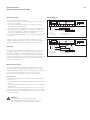
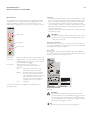
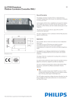
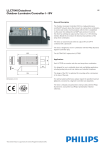
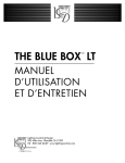
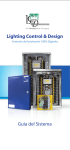
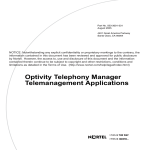
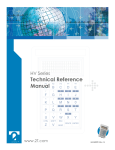
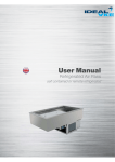
LLC7030 Datasheet
Outdoor Luminaire Controller DALI
1/5
General Description
The Outdoor Luminaire Controller (OLC) is a high-performance
LonWorks® network device that connects to a lamp-driver
combination to control and monitor.
Communication with the OLC is established via the power line utilizing
the LonTalk® open protocol. It interacts with the lamp driver by means
of a DALI interface and when needed, switching its output. Because of
the DALI interface it is possible to control more lamps with less OLC’s,
compared to the 1 – 10V OLC.
The OLC makes use of the DALI commands and therefore extra data
from the driver will be available in the Starsense system.
The OLC can autonomously switch its output ON and OFF if
combined with a photocell.
141.5
63
OLC
LLC7030/00
8222 740 39903
The OLC is designed to work in combination with the Philips Segment
Controller (SC) in a Philips Starsense outdoor lighting telemanagement
system.
Test
2
1
37.5
M6
Applications
Each LLC7030 is able to monitor and control up to two independent
lamp-driver combinations.
156
It is designed for use in highway, residential, street and road lighting
applications including parking lots, ports, train stations and industrial
complexes.
Dimensions in mm
The design of the OLC is optimized for mounting within a luminaire.
05
It is recommended for optimal performance to connect not more than
70 OLC’s to one SC if the two DALI outputs are used (so 140 drivers)
or 140 OLC’s if only one DALI output is used.
The Philips OLC is released and authorized to solely interact with the
Philips SC, consult the local Philips representative if desired otherwise.
When you switch the lamp-driver on/off by a DALI command, there is
the possibility to use the Switched Line Output for another type of load,
like an advert light or Christmas lights.
The LLC7030 OLC DALI doesn’t measure energy consumption; this
information is gathered from the driver. For advanced metering you
may use the LLC7035 OLC DALI that integrates a meter chip with high
accuracy energy metering.
Tip
The Philips Starsense system uses the Philips Starsense
Configurator and Supervisor software. The license to use this
software is embedded in the Segment Controller.
LLC7030 Datasheet
Outdoor Luminaire Controller DALI
General operation
The OLC combines three main functions:
1The controller function receives the incoming commands from the
SC and acts accordingly.
2The OLC switches the Line Output and communicates with the
lamp-driver via the DALI interfaces.
3The monitor function reports data on current, mains voltage, mains
frequency, power factor, burning hours and power consumption of
the connected lamp-driver combination. This information is used to
determine condition of the lamp-driver combination.
A default configured OLC will switch ON its output at maximum level
on power-up.
2/5
Wiring Diagram
Li
The OLC is equipped with a power line transceiver, which can repeat
messages. The SC monitors and controls the dynamic repeating
functionality centrally. If communication fails between the SC and a
specific OLC, another OLC can be designated dynamically by the SC,
which can repeat messages. The SC will autonomously and continuously
keep track of which OLC’s can be reached directly and which ones
require message repeating.
Mounting information
The OLC is designed to be installed inside a luminaire, but can also
be mounted in the pole, gear-trays and separate boxes. If the OLC is
mounted inside a pole it may only be mounted upright. The OLC may
be mounted in any position if the enclosure is IP43 or above.
Please also refer to the installation instruction of the LLC7030.
Released drivers
Currently the lamp-drivers released to interact with the DALI outputs
of the OLC are:
• PHILIPS HID-DV DALI 100/150W SON/CDM with lamps SON and
CDM-TT
• PHILIPS HID-DV DALI Xtreme driver with CPO (Cosmopolis) lamps
60, 90, 140 W
• PHILIPS HF-Regulator II Touch and DALI for PL-L, PL-T, PL-C lamps
Any other component must be validated before it may be used with
the OLC. Contact your local Philips representative about how to obtain
component validation.
Warning
The DALI interface is not using safety isolation
(DA- is internally connected to the Neutral conductor).
Disconnect the main power supply before servicing.
Ni No Lo Ls
Max.
6A
DALI is not using
safety isolation
Lc
DA- DA+ DA- DA+
10 - 11 mm
DALI driver 1
L
DALI driver 2
N
Li = Line input
Ni = Neutral input
No = Neutral output
A backup scenario (safeguard mechanism) is available and can be
configured in different ways. Refer to page 4 of this document and the
Starsense Configurator Manual for more information on this topic.
Repeating
0.25 - 2.5 mm2
Filter
Ls = Switched Line output
Lc = Controlled Line input [Photo cell]
0.25 - 2.5 mm2
Filter
Li
Ni No Lo Ls
DALI is not using
safety isolation
Lc
DA- DA+ DA- DA+
Advert
light
Max.
6A
L
N
Li = Line input
Ni = Neutral input
No = Neutral output
DALI driver 1
DALI driver 2
Lo = Line output (not switched)
Ls = Switched Line output
Lc = Controlled Line input [Photo cell]
10 - 11 mm
LLC7030 Datasheet
Outdoor Luminaire Controller DALI
User interface
The LLC7030 has two pushbuttons. One is for testing the lamp-driver
combination and one to send its unique Neuron® ID number to the
Segment Controller (see Starsense System User Manual for more
information). The test button can also be used as maintenance indicator.
3/5
Test button
• Pressing the test button while the output is OFF will switch the output
ON for 15 minutes at maximum. The output will be turned OFF after
the timer has expired. During this period the red LED 1 blinks slowly.
• Pressing the test button while the output is at maximum level will
cause the output to switch for 15 minutes at dimmed level. The output
will be turned OFF after the timer has expired. During this period the
red LED 1 blinks rapidly.
• Pressing the test button while the output is ON at a dimmed level will
switch the output OFF.
Status LEDs
Attention
The OLCs output will be switched OFF after 15 minutes. Power
cycle the OLC to have the output automatically switched to its
configured power-up level.
Power LED
Maintenance identification
After maintenance has been done on an OLC, press the test button for
4 seconds, an identification message will be send via powerline and will be
made visible in the supervisor software.
Neuron LED
Neuron® ID
Each OLC has a unique fixed 48-bit identifier called Neuron® ID. The
Neuron® ID is printed on the three barcode labels placed on the front
of the OLC, which barcode readers can read.
Status LEDs
LED 1 and 2 will show which output is switched ON.
Power LEDWill show device- or output status, if it’s continuously
in blinking mode the OLC is in error mode, consult
your local Philips representative.
Neuron LED
Will show when Neuron® ID is send.
The yellow service LED indicates the internal
OLC state:
ON: Application-less.The OLC has only
communication parameters loaded.
Blinking: Unconfigured.This OLC state indicates
that it has communication parameters
and an application program and network
address information. This OLC state
is the “idle” state. Commissioning and
configuration need to be performed.
OFF: Configured.
From the factory the OLC is configured for a default lamp and is
operating normally.
OLC label
Attention
When the OLC is installed it is vital for the Starsense system
operation that it knows the Neuron® ID and the location of the
device. A drawing or list indicating which Neuron® ID belongs
to which installed OLC acts as an input for creating the Starsense
telemanagement configuration off-line.
Tip
See Starsense System User Manual for usage suggestions.
LLC7030 Datasheet
Outdoor Luminaire Controller DALI
Powering the OLC ON
Apply mains power to the OLC once it is mounted securely and all
its wiring is connected as shown in the typical wiring diagram. After
power-up, both red LEDs will come ON for 3 seconds. The unit is fully
operational and ready for commissioning and configuration after both
red LEDs go OFF. The green power LED should stay ON continuously
indicating that power is applied and the OLC is running in a correct
mode. The OLC is now in its default configuration. The safe-guard
mechanisms, burning hours counter, power-up behavior and manual
interfaces are operational.
Status messages
The OLC continuously monitors the current internal temperature. Each
newly generated status message is time-stamped. Only the last two status
messages are available via power line messages. Energy consumption
and burning hours are stored in non-volatile OLC memory and can
be obtained, together with status messages, by the SC and Starsense
Supervisor software.
Safe-guard mechanism with photocell
The OLC can (configuration property) fall back onto photocell operation
when it detects a communication failure with the SC. This safe-guard
mechanism prevents light points from staying OFF during the night,
causing dangerous situations, and from staying ON during the day, which
would waste energy. The OLC is equipped with one single-pole 230VAC
input to monitor the photocell operation. When in safe-guard mode,
the OLC will follow the photocell input with its output. A factory default
OLC will switch to the safe-guard state if a 230VAC voltage level is
detected on the photocell input.
Note: It is only possible to connect photocells which use an
electromagnetic relay.
“Door open” detection
The photocell input can also be used as a “door open” detector. Refer
to the Starsense System User Manual on how to configure and use this
feature.
Safe-guard mechanism with back-up scheduler
When no photocell is being used the back-up scheduler can be used.
The OLC can (configuration property) fall back to run according to a
pre-configured schedule when it detects a communication failure with the
SC. The OLC will use this back-up schedule to switch its output. It runs
on its own internal real-time clock if it is in this stand-alone mode. The
switch ON level can be pre-configured through the OLC power-up value.
4/5
Daylight control based on photocell operation
When in daylight control mode (configuration property), the OLC
will follow the photocell input with its output while still receiving and
executing the dimming levels from the segment controller. In this way
the switching points are controlled by the available sunlight and the light
level is controlled by the Starsense system. Lamp-ballast monitoring is
enabled within daylight control. The following functional table is foreseen
for photocell use.
Photocell detection
Dusk
Dawn
Photocell relay
Closed
Open
Photocell Line out
Mains voltage
Nothing
Technical data
Operating conditions
Temperature -25°C to +70°C
Relative humidity 10% to 90%
Max. housing temperature +75°C (on Tc spot, see OLC
cover)
If the Tc rises beyond 85ºC during use, the OLC will switch off the relay
(load).
Non-operating conditions
Temperature Relative humidity Mains connection
Mains voltage
Mains frequency Max. load wattage
Power consumption
Stand-by wattage
Connector block
Mains connector Wire cross section [mm2]
Wire cross section [AWG]
Wire strip length -40°C to +85°C
5% to 90%
220-240V ± 10%
50/60 Hz ± 5%
1000W (2 x 400W) DALI drivers
including advert light
<2W
WAGO 804 series contact cage
clamp connection
0.25 - 2.5 mm2 solid
0.25 - 2.5 mm2 fine stranded
0.25 - 1.5 mm2 fine stranded with
ferrule and plastic collar
0.25 - 2.5 mm2 fine stranded with
ferrule, without plastic collar
20-12 AWG solid
10-11 mm
LLC7030 Datasheet
Outdoor Luminaire Controller DALI
5/5
Power line interface
Channel type PL-20C power line
Coupling Line-to-Neutral, Non-Isolated
Coupling
Protocol ANSI/EIA 709.1
Power line transceivers Compliant to ANSI/EIA 709.2
Frequency band
CENELEC consumer band:
C-band (132.5kHz), automated
B-band (110kHz) selection if
communication on C-band fails
Approval FCC and CENELEC EN50065-1
compliant.
RoHS directive 2002/95/EC
REACH SVHC
Filter
Internal band stop filter, to filter
interference from the lamp driver.
DALI interface
Interface
Number if interfaces
Max. load
LLC7030 OLC DALI
Ordering Data
Type
LLC7030 OLC DALI
322 636 36123
03/2011
Data subject to change
www.philips.com/lightingcontrols
Flammability Glow wire test Protection class Dimensions Weight (PC+ABS Blend)
UL 94V-0 at 1.5mm thickness
850°C
IP20 in any position
IP22 in upright position
H: 15.6 cm, W: 6.3 cm, D: 6.3 cm
0.31 kg
Standards
Safety Immunity Emission EN61347-2-11
EN61547; EN50065-2-1
CISPR15 edition 7.1
Compliant to IEC 60929:2004
Annex E
2 individual digital control outputs
8mA per output
Photocell input
Input
Suitable for magnetic relay type
photocell (without snubber)
Indicators
Power LED (green) This LED is on when the OLC has
power.
Service LED (yellow) This LED is normally off. Blinking
indicates that the application is in
un-configured state.
Output LED (red 2x)
2 red LEDs labelled 1 and 2,
which indicate the output state of
DALI output 1 and 2.
Manual controls
Service button (yellow): Send Neuron® ID
Test button (orange):
Change output states 1 and 2
(100%-50%-OFF)
Barcode code Code128 (Neuron ID)
Back-up scheduler Accuracy ± 0.7%
Safety pre-fuse requirement Max. value pre-fuse: 6 ATH
Packing data
Type
Housing
MaterialBayblend® KU 2-1514
Box dimensions
(mm)
295 x 385 x 165
MOQ
1
LonWorks and Neuron are trademarks of the Echelon Corporation registered in the
United States and other countries.
Qty
Material
24
cardboard
Ordering number
9137 003 38703
EAN code level 1
87115 59732817
Weight (Kg)
net
4.99
EAN code level 3
87115 59732831
gross
5.08
EOC
732817 99