1
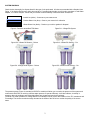
CAPTIVE PURITY
USER’S MANUAL
Please read thoroughly before installing this product!
Congratulations! You are now a proud owner of the finest reverse osmosis filtration system available. Captive Purity has
assembled a high quality water purifying system that turns ordinary tap water into sparkling, great-tasting healthful
drinking and aquarium water by combining filtration and absorption. With this unit you can be assured that your animals
and your family are enjoying the highest quality water possible.
YOUR REVERSE OSMOSIS (RO) or REVERSE OSMOSIS / DEIONIZATION (RO/DI) SYSTEM
SYSTEM SPECIFICATIONS
Sediment Pre-Filter
Carbon Filter
RO Membrane Type
DI CartridgeAvailable on RO/DI Systems
1 Micron Sediment Pre-Filter
0.5 Micron Carbon Block Prefilter (Pro Model)
5 Micron Carbon Block Prefilter (Deluxe Model)
Thin-Film Composite (TFC)
Color Change DI Cartridge (Deluxe Model)
Non-Color Change DI Cartridge (Pro Model)
RO or RO/DI REQUIREMENTS
Operating Pressure
Ideal Input Water Temp.
40-100 PSI
70-77 °F (21-25 °C)
SYSTEM DESCRIPTION
The Captive Purity Reverse Osmosis System is available in a Two-Stage or Three-Stage System. The Captive Purity
RO/DI system is a Four-Stage Reverse Osmosis De-Ionization system.
Sediment Pre-filter
First, the incoming feed water is passed through a micro-tec sediment pre-filter. This filter is required to remove colloidal
and particulate matters that may clog the TFC membrane.
Carbon Block Pre-filter
The second stage of filtration is a carbon block prefilter. This filter removes organics and chlorine from the feed water that
can damage the membrane.
* for the two-stage RO systems, the sediment and carbon block filters are combined into one cartridge.
RO TFC Membrane
The third filtration stage of the system is a high rejection thin film composite (TFC) reverse osmosis membrane. It
removes over 98% of most inorganic salts, heavy metals, bacteria and almost all high molecular weight organics in the
water. The correct waste water to product water ratio is 4 to 1.
Deionization Cartridge (Available on RO/DI Systems)
The fourth stage moves water through a Deionization Cartridge. As water passes through a bed of ion exchange resin,
these resins attract and absorb ionic contaminants: cation resins absorb positively charged ions, and anion resins absorb
negatively charged ions. They are capable of producing 18 meg-ohm-cm resistivity water. Deionization cartridges are
designed to reduce silica, nitrates and phosphate levels in the low ppb range. It is an excellent system for removing
dissolved solids and gases.
1
SYSTEM DIAGRAM
Check the box thoroughly for all parts listed for the type of unit purchased. All units come standard with a Garden Hose
Fitting. If the feed water (faucet or sink) does not have ¾” garden hose threads, you will need to purchase a Feed Water
Adapter, or a Faucet Coupler. Check with your retailer for the availability of these and other accessories.
Intake Line (white) – Connects to your water source
Product Water Line (blue) – Goes to your reservoir for collection
Waste Water Line (black) – Drains to your sink or garden for disposal
Figure A: Pressure gauge/Dual TDS Meter
Figure B-1: 2-Stage RO System
Figure B-2: 3-Stage RO System – Deluxe
Figure B-3: 3-Stage RO System – Pro
Figure B-4: 4-Stage RO/DI System – Deluxe
Figure B-5: 4-Stage RO/DI System – Pro
The pressure gauge (Figure A; standard on RO/DI Pro models) will allow you to monitor the pressure of the system and
make sure that the filter is receiving sufficient water pressure to operate efficiently. It will also indicate, via a drop in
pressure, when the sediment and carbon block filters are clogged and need to be replaced.
The Dual TDS meter (standard on 4-stage RO/DI Pro models) is used to monitor the condition of the TFC membrane and
DI cartridge. The sensor can also be easily relocated to the intake of the RO unit to monitor the quality of the source
water.
2
INSTALLATION INSTRUCTIONS
NOTE: It is recommended to have this unit installed by a licensed plumber to adhere to all local codes. It is the
responsibility of the purchaser to insure that all fittings are tight and that codes are met.
WARNING: Household water pressure can cause leaks and damage the surrounding building or fixtures if not properly
installed. User must check all fittings for tightness. Bayside Aquarium Supply assumes no responsibility for water
damage due to leaks.
Captive Purity Systems can be mounted to any secure location using hardware screws. Keep in mind that the filter
system will gain a substantial amount of weight when it is full of water. For this reason, it is necessary that the filter
system be mounted to a strong backing. Mount the filter system level with clearance for all housings and hoses. Also
keep in mind that there will be space needed to accomplish regular maintenance of the filter system such as pre-filter
removal. If needed, additional hardware and plumbing can be found at most hardware or plumbing supply stores.
Attach the garden hose adapter to your cold-water source. Never run hot water (greater than 100 degree Fahrenheit, 38
degree Celsius) through the system.
Place the black waste water line and blue product water line into your drain. Do not restrict flow from these lines. Do not
install the TFC membrane at this point. Slowly open the cold water supply valve and allow the first two housings to fill. You
may use pressure up to 100 psi (5.5 bar). Double check the system to ensure that all fittings are tight and leak-free before
leaving the system unattended.
* for a four-stage RO/DI unit, you will need to first remove the DI cartridge.
Allow the water to run for 15 minutes to flush the sediment and carbon-block filter cartridges. Flushing the pre-filters will
help to maximize the TFC membrane life.
Next, turn off the water supply. Remove the TFC membrane from the protective bag and install the membrane into the
TFC housing at the top of the RO unit. You will need to disconnect the tubing to be able to unscrew the cap. Securely seat
the TFC membrane in to the housing: there should be about ¾” of space from the lip of the housing to the top of the TFC
membrane. Once the TFC membrane is seated, screw on the top and reconnect the tubing. Reverse osmosis membranes
are packed with an anti-bacterial agent to keep them sterile prior to use. This agent should be flushed away to avoid
human or animal consumption. Turn on the water once again and allow the unit to run for 30 minutes to flush out the antibacterial agent.
After the system has been allowed to run for 30 minutes, the water from the product water line can now be collected for
use.
* for a four-stage RO/DI unit, you can now reinstall the DI cartridge and start collecting water for use. Trapped air in the DI
cartridge is a normal condition and will not affect the operation of the DI cartridge.
MEMBRANE & FILTER CARTRIDGE REPLACEMENT SCHEDULE
Sediment Cartridge – change when visibly dirty (4-8 months)
Carbon Cartridge – change at the same time the sediment filter is changed (4-8 months)
DI Cartridge – For the Deluxe models, the color of the DI resin will start to turn orange from the bottom up. Replace the
cartridge once it has reach to about 1” from the top of the cartridges. For the Pro models, use your TDS meter to
determine when the cartridge should be changed. You will notice a dramatic rise in the TDS level once the resin is
exhausted.
Thin Film Composite (TFC) Membrane – should be changed every 2-3 years or when TDS reading is above 30-40 µs.
The use of a flush valve kit is recommended to help extend the life of the TFC membrane.
*All listed service times are approximate. Actual service life may be longer or shorter depending on the water source
quality and how often the unit is used.
STORAGE
When the unit is not in use, it is important to keep the TFC membrane hydrated. The TFC membrane must not be allowed
to dry out. Keep the unit in a cool location and keep all inlet and outlet lines above the unit so the water will remain in the
3
unit. If the RO (or RO/DI) system will not be used for more than 4 weeks, remove the TFC membrane and store it in a
refrigerator inside a Ziploc bag filled with a small amount of purified water. Do not allow the RO (or RO/DI) unit to be
exposed to freezing conditions or temperatures above 100°F.
TROUBLESHOOTING
Your new Captive Purity RO or RO/DI filter should work trouble free out of the box. If you have difficulties or questions,
please contact your local Captive Purity Retailer. NOTE: The water supply should be turned off and the water pressure
should be bled off prior to working on the filter system itself. Following are some common problems and their solutions:
Problem: The filter system does not produce any product water.
Solution: A missing, clogged or defective flow restrictor is most likely the cause of this problem. Check the waste water
line to make sure that the capillary flow restrictor is installed inside the tubing. If the flow restrictor is clogged, it will need
to be replaced. Please contact your local dealer and inform them of the exact model of your Captive Purity System. Flow
restrictors are different based on the gallons per day rating of your filter system.
Problem: I’m not getting the rate capacity out of the unit what could be wrong?
Solution: Output capacity of your RO or RO/DI unit can be affected by many variables. Temperature of source water, low
water pressure, clogged sediment or carbon cartridge, and exhausted membranes are some variables that can affect your
water output. The production rates are rated at 65PSI and 70º F feed water temperature. Booster pumps can be used to
boost the line pressure and increase water output. If the problem is caused by a filter cartridge or membrane, it will need
to be replaced.
Problem: Too much product water, little waste or resin exhausts quickly
Solution: This is usually the result of the TFC Membrane not seated properly or a ruptured membrane. Open the TFC
Housing and firmly push the membrane in place. If the membrane is ruptured, it will need to be replaced.
Problem: Not enough product water, lots of waste
Solution: Check the TDS, high TDS can lower the output. Check the Temperature of the feed water, low water
temperatures like 50º F, 10° C will restrict the output to half. Check the pressure, the ideal water pressure should be 65
psi.
LIMITED WARRANTY
Bayside Aquarium Supply, Inc. warrants each new Reverse Osmosis & Deionization system to the original owner only to
be free from defects in material and workmanship under normal use and conditions for a period of 90 days from the date
of original purchase.
Bayside’s liability under this warranty shall be limited to repairing or replacing on Bayside’s option, without charge, F.O.B.
Bayside Aquarium Supply’s factory, any product of Bayside’s manufacture. Bayside will not be liable for any cost of
removal, installation, transportation, or any other charges which may arise in warranty claim.
NOTE: This warranty is void if the product is: 1) Damaged through abnormal operating conditions, accident, abuse,
misuse, unauthorized alteration, or repair. This includes, but is not limited to, failure to regularly replace carbon and
sediment filters. 2) Damaged by poor local tap water conditions. 3) Damaged due to connection of equipment other than
supplied by Bayside Aquarium Supply, or modification by the user. 4) Damaged by hot water, freezing, flood, fire, or acts
of God.
This warranty is valid only in the U.S. and is non-transferable. No other warranties are expressed or implied and any
other warranties required by law are limited in duration to 90 days. This product is not warranted for any specific purpose.
Bayside Aquarium Supply will not be responsible for consequential damages arising from installation or use of the
product, including any flooding which may occur due to malfunction or faulty installation including, but not limited to failure
of installer to tighten all fittings.
Gallons per day are not warranted since it is dependent on the users water conditions (i.e., temperature, pressure, and
total dissolved solids).
4