1
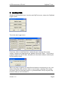
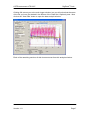
© ETB Instruments LTD 2007
DigiDash2 Tools
DigiTools
Software User Manual
www.etbinstruments.com
Version: 1.0
Page 1
© ETB Instruments LTD 2007
DigiDash2 Tools
1
DigiDash2 DigiTools Introduction .................................................................................................................... 5
2
Loading Data ............................................................................................................................................................... 6
3
Comparing two laps................................................................................................................................................ 8
4
Selecting the data features to be plotted ................................................................................................. 10
5
Track Mapping ......................................................................................................................................................... 12
5.1
6
7
Mini Track Map .........................................................................................13
Markers and Labels............................................................................................................................................... 14
6.1
Maximum, minimum and average statistics ..........................................16
6.2
Labels ........................................................................................................16
Examining data in detail – Zoom and Pan.................................................................................................. 18
7.1
Function Key Shortcuts ...........................................................................19
8
G Circles..................................................................................................................................................................... 20
9
Data Smoothing.......................................................................................................................................................22
10
Changing the X axis.............................................................................................................................................. 23
11
Engine Analysis .......................................................................................................................................................24
12
Lap times tab ........................................................................................................................................................... 26
13
14
12.1
Distances & average distance.................................................................26
12.2
Split times/Segment times/deltas ...........................................................26
12.2.1
Split/Segment times............................................................................26
12.2.2
Sorting Laps .......................................................................................26
Option tab ................................................................................................................................................................... 27
13.1
G sensor settings .....................................................................................27
13.2
Speed correction ......................................................................................27
Exporting data ......................................................................................................................................................... 28
14.1
Printing or saving plots ...........................................................................28
14.2
Exporting and using CSV files ................................................................28
Version: 1.0
Page 2
© ETB Instruments LTD 2007
DigiDash2 Tools
15
Video Overlay........................................................................................................................................................... 30
16
Split times, Segment times and lap comparisons............................................................................... 32
17
GPS Features............................................................................................................................................................ 36
18
Analog Channels.................................................................................................................................................... 38
18.1
19
Analog Sensor Calibration ......................................................................40
Data Features ........................................................................................................................................................... 41
19.1
Pro tab .......................................................................................................41
19.1.1
RPM....................................................................................................41
19.1.2
Speed .................................................................................................41
19.1.3
Gear*10 ..............................................................................................41
19.1.4
Oil Pressure........................................................................................42
19.1.5
Oil Temperature..................................................................................42
19.1.6
Water Temperature ............................................................................42
19.1.7
Aux Pressure ......................................................................................42
19.1.8
Fuel % ................................................................................................42
19.1.9
Battery ................................................................................................43
19.1.10
Brake % ..........................................................................................43
19.1.11
G Lat *10 ........................................................................................43
19.1.12
G Long * 10.....................................................................................43
19.1.13
Odometer........................................................................................43
19.1.14
Lap Time.........................................................................................43
19.1.15
Time Slip, Odo Slip .........................................................................43
19.2
Pro+ Extra tab ...........................................................................................44
19.3
Ch 1-8 tab ..................................................................................................44
19.4
Ch 9-16 tab ................................................................................................45
19.5
Other tab ...................................................................................................45
Version: 1.0
Page 3
© ETB Instruments LTD 2007
19.5.1
GPS Module – Speed and Altitude.....................................................45
19.5.2
Gear Module – Act Gear *10 ..............................................................45
19.5.3
Sensor Module 1, 2 – Additional speed channels ..............................45
19.5.4
Engine Analysis ..................................................................................46
19.6
20
DigiDash2 Tools
Math Ch 1-3 tab.........................................................................................46
APPENDIX 1 – Warranty ........................................................................................................................................ 48
Version: 1.0
Page 4
© ETB Instruments LTD 2007
DigiDash2 Tools
1 DigiDash2 DigiTools Introduction
This document describes the DigiTools software that is provided with the DigiDash2
Lite, DigiDash2 Pro and DigiDash2 Pro+. It shows a selection of tips and techniques
for analysing data logged by your DigiDash 2 using the Digitools Software. It
assumes that
you have the Digidash properly configured for your car (revs, speed, brakes, etc)
you have run it at a race track to generate some data (at least one set)
you have installed the Digitools software on your PC
you have downloaded that data from the Digidash to your PC, with the Digitools
software installed.
Basic instructions on the installation and use of the DigiDash2 and DigiTools is
contained in the main DigiDash2 Manual.
Version: 1.0
Page 5
© ETB Instruments LTD 2007
DigiDash2 Tools
2 Loading Data
Starting at the most basic level, from the main DigiTools menu, choose the “DigiDash
Logger” option.
This is the main Logger menu
From here, click on ‘Load Data Set A’, which will open a standard file browse
window. Browse to the appropriate file, highlight it and press ‘Open’. You will see a
progress window as the file loads, followed by an information window confirming the
file successfully loaded.
TIP: It may help to organise your data files into folders for each track you visit – this
makes finding data from previous visits to a circuit easier. Adopting a file naming
convention (such as track-date-session, e.g. Brands-050927-race1) may also help
locate the data you are interested in.
Version: 1.0
Page 6
© ETB Instruments LTD 2007
DigiDash2 Tools
Clicking OK returns you to the main logger window, but you will notice that the name
of the file you have just loaded in the bottom of the ‘Data Set A Options’ pane. Now
click on the ‘View Data’ button to open the data analysis window.
Each of the remaining sections of this document start from this analysis window.
Version: 1.0
Page 7
© ETB Instruments LTD 2007
DigiDash2 Tools
3 Comparing two laps.
You can compare 2 laps of data, either from the same data file or from separate files
(sessions).
Click on the “View” tab on the left hand pane, and towards the top of the View
Options pane click the “Lap Overlay” option. You will be prompted with a dialog box
to choose laps from the Lap Times area. Click on the ‘Lap Times’ tab of the right
hand pane to display all laps in the current file. The upper table shows all the laps in
data set A, with details of the best lap below. The lower table shows data set B’s
laps, if you have loaded a second set of data.
Click on the “Lap Times” tab of the main pane. Each lap of the loaded file (or files) is
displayed in a separate table for each file with the lap time, distance, MPH and split
times.
Note that the distance recorded for that lap should be checked to ensure that any lap
you are considering is complete and correct. For instance, sometimes because of
the position of other cars, the lap trigger may not “see” the trackside beacon on one
lap – the DigiDash will miss the end of that lap and will instead record one long lap
whose distance is roughly double the norm. At the bottom of each lap table are
statistics highlighting the best lap, a theoretical best lap time (taking the aggregate of
the lowest time recorded in each segment) and the average distance of all laps.
If you identify unrepresentative laps, you can uncheck the tick box at the left of that
row. This lap will then not be included in calculation of any of the statistics.
Version: 1.0
Page 8
© ETB Instruments LTD 2007
DigiDash2 Tools
Using the Lap Time Options pane you can choose whether the split times are used to
display split times (the cumulative time to reach each split point in the lap) or
segment times (the time to travel between 2 consecutive split points). You can vary
the number of split points – the chosen number of split points will be distributed
evenly around the lap distance.
Using the Lap Time Options pane you can also sort laps either by lap number
(default, unsorted), lap time (to highlight your best laps) or by time in any selected
segment.
You can now select the 2 laps you wish to compare in the drop down boxes at the
bottom of the lap times pane. These laps can be from either or both the data sets, so
for instance you can compare the best laps from each of 2 sessions or 2 laps from
the same session. Note that all laps from session A and then from session B are
shown in both drop down lists.
On the lower right of the lap times pane are the “further lap analysis” radio buttons –
if you have selected 2 laps you can choose which of these laps will be used to draw
the G track map and G circles.
Clicking on the “plot data” tab on the main pane will display the selected data for both
laps overlayed over each other. By default, selection 1 is in solid line, selection 2 in
dotted line. You can change these display options using the buttons at the bottom of
the main pane.
Version: 1.0
Page 9
© ETB Instruments LTD 2007
DigiDash2 Tools
4 Selecting the data features to be plotted
Click on the “Data” tab on the left hand pane.
Clicking on the check boxes on this pane switches on or off the trace for the
corresponding data feature for both selected laps or sessions.
You can change the colour of the trace for any data feature for one or both the
selections to make the plot easier to read. You can also use the buttons at the
bottom of the main pane to select whether each selection is plotted at all, as a solid
or dotted line or points.
TIP: Selecting the “Time Slip” or “ Odo Slip” trace at the bottom of the data tab
displays a plot of the cumulative difference between the 2 laps shown. At most one
of these trace options is available, depending on whether the X axis selected is
Distance or Time.These traces are very useful for highlighting where time is being
won or lost between 2 laps- even if the ultimate lap time is similar.
To allow the differences between the laps to be clear, you can select a scaling factor
for the slip plot.
Version: 1.0
Page 10
© ETB Instruments LTD 2007
DigiDash2 Tools
TIP: You can save your preferences for data trace selection, colours etc by going to
the File tab and clicking on ‘save file’ in the Display Preferences section. If you save
as ‘default.cfg’ in the digidash directory, the current settings will be used as default
each time you open Digitools. You may find it useful to save settings for different
types of data analysis, for instance:
“systems analysis”, plotting all plot data for the session and displaying speed, oil and
water temperature and pressure, aux. pressure and battery voltage. This is useful for
seeing how your engine is coping throughout the session.
“Lap analysis”, plotting RPM, Speed, Gear, Brake, G lat, G long and delta Odo.
These traces are more useful for comparing your fastest laps from the session or
with a previous session
Each configuration can be loaded in a moment using the “Load File” button in the
Display Preferences section of the File tab.
Version: 1.0
Page 11
© ETB Instruments LTD 2007
DigiDash2 Tools
5 Track Mapping
Digitools can draw a map of the circuit so long as the speedo sensor and G force
sensors are correctly configured and logged. The software uses the lateral G force
and the distance travelled to draw the map, and applies error correction to ensure the
map forms a complete circuit.
Note: With the Pro+ and optional GPS module, more accurate track mapping can be
displayed from the GPS positioning data. This allows actual lines through each
corner to be compared – a level of detail not possible with the G force mapping.
To enable the track mapping, you need to plot the data by lap and to select one or 2
laps to view (see “Comparing two laps”).
Clicking on the “Track Map” tab of the right hand (data plot) pane shows a full size
map of the track.
The line forming the track is coloured red or green. By default, this colour indicates
the longitudinal G at that point in the lap – Green for acceleration and Red for
deceleration. By selecting the ‘View Braking (Blue)’ check box, you can highlight on
the track map where brakes are being used.
TIP: By using the braking view on the track map, you can see where on the lap you
are slow coming from the accelerator to the brake pedal, and where you may be
coasting off the brakes rather than getting back on the power.
Version: 1.0
Page 12
© ETB Instruments LTD 2007
DigiDash2 Tools
In the Track Analysis section of the pane you can change this, for instance to Delta
Segments, which (where you have 2 laps selected) shows the difference in times
between the 2 laps for each segment, allowing clear visual comparison of where on
the circuit one lap is better than another. Checking the ‘Delta Seg Width’ check box
alters the thickness of the track line (in addition to its colour) depending on the
amount of difference between segment times of the 2 laps for each segment.
On the upper right corner of the track map pane you can select the Plot Mode –
Circuit or Sprint/Hill Climb. In Circuit mode when using G force track mapping,
Digitools applies error correction to the data to ensure that the 2 ends of the lap meet
up. If you are logging data from a ‘point to point’ run (i.e. not a circuit where the 2
ends of the run should meet up) selecting hill climb or rally stage will plot the data in
its raw (uncorrected) form.
To switch to using GPS data for the map, use the “source” pane to the right of the
window.
If using G force mapping, only 1 lap is mapped – use the Track Map Lap options to
select which lap is plotted at any time.
If using GPS mapping, you can use the “Options” pane to choose to overlay the
maps of both laps and whether the second lap should be displayed as a dotted line to
allow the 2 laps to be differentiated.
5.1 Mini Track Map
In the Plot Data tab on the main pane, you can display (or switch off) a mini track
map by checking (or unchecking) the “Lap Track” box in the View tab of the left hand
pane. This mini map is useful as a reference when looking at the data, and coloured
dots will indicate where on the lap each marker is currently placed (see “Markers”
section).
Version: 1.0
Page 13
© ETB Instruments LTD 2007
DigiDash2 Tools
6 Markers and Labels
You can set markers on the plot data, which allow you to take accurate pinpoint
readings of any trace, and show the differences between 2 points (in terms of
time/distance and reading) by using markers.
Click on the “Marker” tab on the left hand pane.
Click on the “on” option on the radio button at the top of the Marker tab. Now, if you
click and drag your mouse pointer in the main plot area, blue or red horizontal marker
lines follow the mouse until you drop them at the desired point on the plot. Once you
have placed the first marker, you can introduce the second marker by dragging the
mouse from the left edge of the plot area.
To reposition a marker, click the mouse near the current position and drag it to the
new position. The marker closest to where you start dragging will be picked up, the
other marker will remain where it is.
With markers switched “on”, as you move the mouse over the plot area you can see
the readings corresponding to the current cursor position in the white area of the
“Marker Data” section.
Version: 1.0
Page 14
© ETB Instruments LTD 2007
DigiDash2 Tools
In the example above, you can see the red and blue markers have both been
positioned. From the mini track map at the bottom right of the plot area the blue and
red dots show where on the circuit the markers have been placed (the braking area
on the entry to Druids at Brands Hatch Club, UK in this case). In the main plot area,
you can see the red and blue “cross hairs” of the 2 markers, corresponding to the
highest speed at the end of the straight and the lowest speed at the apex of the
corner.
Looking at the “Marker Data” area of the left hand pane, we can see the blue
marker’s figures printed in blue, showing that it is at 41.94 on the Y axis and 15.72 on
the X axis. Since we have aligned this marker with speed, this indicates that the car
was doing 41.94 MPH at the apex, and this was 15.72 seconds into the lap.
Similarly the red marker (just as the brakes are applied at the end of the preceding
straight) shows 106.4MPH and 12.01seconds.
The black Delta figures show that between these 2 markers the car lost 64.46 MPH
over the course of 3.72 seconds. This might be useful information for assessing how
efficient the car’s brakes (or the driver’s use of them) are.
You can use similar marker techniques for measuring acceleration times, G loadings
etc.
Version: 1.0
Page 15
© ETB Instruments LTD 2007
DigiDash2 Tools
6.1 Maximum, minimum and average statistics
At the bottom of the Marker tab is the Statistics area. This is only available if the X
axis is set to “Time” (e.g. not distance, etc).
You can use this facility to see the maximum, minimum or average of any one of a
number of data features, in each of the selected data sets. You can choose to
measure the statistics either across the whole selection or just the data currently
visible in the plot area (see Zoom and Pan section for how to narrow down the visible
data set).
TIP: This feature is useful, for instance, for very quickly seeing how hard a session
has been on the car:
What were the maximum revs? (has the driver ‘buzzed’ the engine)?
What was the maximum oil and water temperature?
What was the minimum oil pressure during a lap?
What was the average lap speed?
The statistics can show you this information far more quickly and accurately than
looking through the data and placing markers.
6.2 Labels
You can set labels on the plotted data to highlight features of a plot (for instance if
you are printing it out), or as reminders.
Version: 1.0
Page 16
© ETB Instruments LTD 2007
DigiDash2 Tools
Labels can consist either of the X and Y coordinates of the marker (use “Set Label”)
or your own text reminder (use “Set Text”).
To set a label, select either “Set Label” or “Set Text” in the Labels area of the Marker
Tab, then drag the mouse pointer to where you want to place the label. If you are
using “Set Text”, type the text you want to use as a label into the white text box
before placing the label.
You can switch between viewing or not viewing the labels on the plot by using the
“view” and “Off” radio buttons.
If you make a mistake, or want to reposition a label, click “clear last” to remove the
last label you placed. You can then re-place it. Clear all removes all labels you have
set.
You can save a set of labels or reload a previously saved set using the save and load
labels buttons. For instance you could create a set of labels identifying each of the
corners for a particular circuit for easy reference. Save this, then you can reload it for
any subsequent data set, and the labels will appear in the same positions.
Version: 1.0
Page 17
© ETB Instruments LTD 2007
DigiDash2 Tools
7 Examining data in detail – Zoom and Pan
Sometimes you need to examine part of a lap or session more closely than is
possible with the whole lap or session on screen. DigiTools allows you to zoom in on
a section of data, and then “Pan” around (like a movie camera) to move the view to
different areas of the data.
Click on the View tab in the left hand pane. The visible section of data is changed
using the options in the ‘Plot Area Zoom Options’ section.
To zoom into an area of the data you are interested in, click the “Zoom Box” radio
button. Then click in one corner of the rectangular area of the displayed data that
you want to focus on, and drag the pointer over to the opposite corner – a rectangle
is drawn showing the area that will be displayed. When you release the mouse
button the area within the rectangle will be expanded to fit the full available screen
area. Axes are re-scaled automatically to make the data fit the screen.
In the example below we have zoomed in on the braking zone on the approach to
Druids - the same area we looked at in the Markers section. You can see much
more clearly the transition from throttle to brake, the 3 down changes and the degree
of trail braking as the lat G trace (purple) starts to show cornering about half a
second before the brake is released. Note also from the longitudinal G trace (blue)
how the deceleration reduces as the cornering begins – the brakes have been eased
to allow the tyres to cope with the cornering. We will analyse this in more detail in
the G Circle section.
If you are not happy with the area you have selected with the Zoom Box, or you want
to return to a wider view you can return to display all the data by clicking on the “Full”
button
Version: 1.0
Page 18
© ETB Instruments LTD 2007
DigiDash2 Tools
Having zoomed in, you can move the view around the rest of the data (“Pan”) by
clicking the “Pan All” radio button. Now, clicking and dragging the mouse in the plot
pane moves the data under the window. If you only want to go left and right (and not
up and down) you can click “Pan All Horiz”.
7.1 Function Key Shortcuts
Pressing “F1” will bring up a help guide to the function key shortcuts available in
DigiTools. These function keys cover most of the frequently used zoom, pan and
marker actions, greatly speeding up the analysis of your data.
Version: 1.0
Page 19
© ETB Instruments LTD 2007
DigiDash2 Tools
8 G Circles
If you have read any books on car performance and control you should be familiar
with the concept of the “traction circle”. In summary, a tyre can only provide a certain
amount of grip, and the driver must choose in which direction this grip is used, and
how much grip is used from time to time. Therefore, if the driver is asking the tyre to
use 100% of its grip in braking, any attempt to turn the car without reducing the
braking effort will result in the car sliding or losing control.
If we plot the lateral and longitudinal G forces produced by a car at the limits of grip,
in theory we might expect the pattern to form a circle – this is known as a traction
circle or “G Circle”. In practice of course, the tyres have differing levels of grip in
cornering (across the tyre tread and across the car’s track) from braking (along the
tyre tread and along the car’s wheelbase) and acceleration (where there may only be
1 pair of tyres contributing to the acceleration on a 2 wheel drive car).
The G Circle tab on the right hand pane plots the lat and long G readings for each
moment of data on a G circle.
If you are viewing all plot data, the G circle will cover the entire session. If you are
viewing lap overlay, the G circle will be plotted for the lap(s) you have selected.
The laps are colour coded (green and purple) and each can be switched on or off
using the check boxes in the “Data Key” area at the bottom of the main pane. The
points where brakes are applied are highlighted with a lighter shade. Note on the
example above how the lower part of the plot is lighter green showing how higher
levels of deceleration are achieved under braking, as you would expect.
You can use the Zoom/Pan functions at the bottom of the main G Circle pane to
focus on smaller areas of the plot or to make it fit the screen better.
Version: 1.0
Page 20
© ETB Instruments LTD 2007
DigiDash2 Tools
On the View tab on the left pane, there is a check box for “Lap G Circle”. Checking
this box switches on a miniature version of the G circle plot on the main “Plot Data”
tab.
This mini G circle plot comes into its own when combined with markers. Switch on
the markers (in the Marker tab in the left hand pane, as described in the “Markers
and labels” section), and as you drag a marker across the data, the corresponding
point on the G circle is highlighted by a spot of the same colour.
By moving the markers back and forth, especially around transition areas between
braking and acceleration, you can see how efficiently the tyres are being used by the
driver. Ideally, the point will “roll” around the circumference of the circle as the
brakes blend into cornering into acceleration. Any time the point is not at the edge of
the circle plotted, the tyres are not producing the maximum possible G force or
traction.
Zooming in to a more detailed view of the data (see the “zoom and pan” section)
allows a much more detailed analysis of these transitions.
This analysis is complicated by the fact that the car is not grip limited accelerating
away from a fast corner (it is power limited), and differing track conditions (camber,
gradient change) may affect the grip available.
Version: 1.0
Page 21
© ETB Instruments LTD 2007
DigiDash2 Tools
9 Data Smoothing
By default, when a data file is loaded into the Digitools, the data is displayed as it
was logged, which may show noise or interference. Inevitably, the raw data logged
has spikes or uneven readings – for instance the G sensors will pick up shocks and
bumps from the track.
If you would rather filter out this noise and see smoother data traces, the smoothing
can be used function to even out these shocks or noise and make the data easier to
read and analyse. Note, though, that smoothing is effectively removing information
from the trace, so should be used with care.
To see smoothed data, on the View tab, check the “Filter when Data Loaded” box at
the bottom. Then return to the File tab and load the data session. This will apply a
small amount of smoothing to every trace.
If you only want to smooth one or a few traces, you can select the trace in the drop
down list of the Data Smoothing area, and click Smooth. If you click the Smooth
button multiple times, more and more smoothing will be applied and progressively
more unevenness will be removed from the selected trace.
As you are removing information from the trace by smoothing, to go back to an
unsmoothed trace you must reload the file from the file tab.
Version: 1.0
Page 22
© ETB Instruments LTD 2007
DigiDash2 Tools
10 Changing the X axis
The data tab (left hand pane) gives the option to change the data used for the X axis
from the default of “time” to any one of the main DigiDash2 Pro data features.
The obvious alternative to time is distance- choosing distance allows 2 laps to be
compared so that (apart from allowances for different recorded distances for different
lines, wheelspin or brake lockup) each lap is at the same place on the lap for a given
point on the X axis. So:
you can see the relative speeds etc. for each lap at, say, the apex of the first corner,
or
see where in one lap the driver is on the brakes at a later point on the circuit (rather
than just being later on the brakes as he was behind the comparative lap by that
point but perhaps actually braking at the same place).
Another useful option is to plot against revs on the X axis.
The figure above shows oil pressure plotted on the Y (vertical) axis, with RPM on the
X axis, for a single lap with the oil heated up. You can see how oil pressure rises
more or less linearly with revs until around 65PSI, where the pressure bypass valve
limits the pressure regardless of revs.
Other uses might be to plot airbox pressure against speed, etc.
Version: 1.0
Page 23
© ETB Instruments LTD 2007
DigiDash2 Tools
11 Engine Analysis
The engine analysis tab presents a plot of engine power and torque similar to that
which you would get from a rolling road session. These curves are calculated from
the longitudinal G, speed and RPM data throughout the data session.
The maximum power and torque recorded is calculated at each RPM point and these
maxima are plotted. So, only time spent at full throttle is relevant to this plot.
2 curves can be plotted simultaneously. However, these 2 plots will always relate to
the whole data files loaded, rather than (as in the “plot data” tab) laps selected in the
Lap Times tab. If only one file is loaded into the DigiTools, only one plot will be
available.
Plot colours are controlled by the Power and Torque settings at the bottom of the
Data tab’s, “Other” sub-tab, in the left hand pane. The appearance (solid, dotted line
or points) or non-appearance (on or off) of each plot is controlled by the settings at
the bottom of the Plot Data tab in the right hand pane.
The RPM Histogram plot shows the proportion of time spent at each RPM level in the
plotted data. This is useful for evaluating gearing on a lap, and which areas of the
power curve are most important to lap time (for instance in the plot above, it is clear
that little time is spent below 7000 RPM, so there is little point in trying to increase
torque or power below this level.
As you move the cursor across the engine analysis plot area, at the bottom left of the
engine analysis tab are the data corresponding to the cursor position – power,
torque, RPM as well as estimated flywheel BHP.
Version: 1.0
Page 24
© ETB Instruments LTD 2007
DigiDash2 Tools
The base power calculation is “power at the wheels” since it is calculated from the
car’s performance on the road. Power at the flywheel can be estimated
(independently for each data file) by configuring the transmission losses. This is the
amount of power lost between the engine flywheel and the road – in the gearbox,
transmission, differential, bearings and tyres. The default settings of 12% plus a
fixed 10bhp loss are commonly accepted, but you may change these if you think your
car is more or less efficient.
The plotting of the flywheel power can be turned on or off and its colour (for each
data session) controlled in the “Plot Control” area.
Also configured for each data file is the car’s weight. The default value is that
configured into the Digidash by the configuration tool. However, as the car runs
through a session, it will have differing levels of fuel and hence different weight.
Different drivers will also affect the car’s weight. Remember, the weight used here
should be the all up weight of the car as it is running on the track, not the dry weight
or kerb weight excluding driver, and will directly affect the power levels (but not the
overal shape) of the plotted curve.
By carefully setting the configuration for each data session, power output between
different cars, or with different settings on the same car can be compared, just as you
would do on a rolling road, though potentially at much lower (or no) cost. Ideally, if
you are working on engine tuning, you would perform repeatable runs on a straight
piece of track to avoid differences caused by corners, driving technique, hills etc.
Version: 1.0
Page 25
© ETB Instruments LTD 2007
DigiDash2 Tools
12 Lap times tab
12.1 Distances & average distance
In the lap times tab of the right hand pane, the information on each lap includes the
Distance recorded for that lap. At the bottom right of each file’s information is the
average distance for all laps.
When considering lap times, check that the lap distance is close to the average –
sometimes (due perhaps to interference from another car or poor positioning of the
sensor or beacon) the lap will be triggered by a different beacon on the pit wall or
may even miss the beacon for a lap (leading to a double length lap). Checking the
lap distance ensures that you are examining a full valid lap, rather than one that is
significantly shorter or longer than the real lap length.
12.2 Split times/Segment times/deltas
At the bottom of the lap times tab, there is a set of radio buttons that affect the data
displayed in the split/sec columns in the main data tables.
12.2.1 Split/Segment times
Split times show the cumulative lap time at each split point for each lap.
Segment times show the time taken to cover the distance from one split point to the
next.
12.2.2 Sorting Laps
Sometimes it is helpful to see the laps in a session sorted by lap time or by segment
time to see the best time and the spread of times below that. Use the Sort check box
and Sort Parameters to achieve this.
Version: 1.0
Page 26
© ETB Instruments LTD 2007
DigiDash2 Tools
13 Option tab
13.1 G sensor settings
Depending on the orientation in which your Digidash Logger unit is mounted, you
may need to use the “G Sensor Settings” options.
If the logger box is mounted “across” the car (with the cable connections to the left
and right of the car), you should check the “swap lat and long” box to align them
correctly. If it is mounted upside down you may need to change the sign of either Lat
or Long G.
Note that the DigiDash configuration allows you to correct for these orientation
issues. You should therefore only need to use this facility of DigiTools if one of your
2 files for comparison has not been properly configured in the dash.
13.2 Speed correction
By default, the Digidash speed reading is calibrated to over-read by 3%. This
ensures that it does not under read – vital for legality on the road.
To return to the true speed, check the “-3% calibration” box in the Speed box. With
the box unchecked, you may be over-estimating your speed on track – good for your
ego and for psyching out the opposition, not so good for accurate analysis.
Version: 1.0
Page 27
© ETB Instruments LTD 2007
DigiDash2 Tools
14 Exporting data
14.1 Printing or saving plots
From the File tab, you can save an image of the current contents of the plot area
either by printing it (“Print to Device” button) or saving it to a bitmap image file (“Print
to File .bmp” button).
You can also copy the plot image to the clipboard using the “Send to Clipboard”
button). The image can then be pasted into another document, like this:
14.2 Exporting and using CSV files
There may be times when Digitools does not allow you to do the analysis you
require. Digitools allows you to export the data from a lap as a Comma Separated
Variable (CSV) text file.
CSV files can be read into a spreadsheet very simply, and from there you can use
the spreadsheet’s calculation, statistics and plotting functionality to work with your
data.
To export the data, go to the lap times tab, and select the lap that you want to export
in either the Selection 1 or Selection 2 drop down box at the bottom. Over in the
bottom right corner, select the Lap Selection radio button (1 or 2) that corresponds to
the lap selection you are interested in. Click on “Export Lap” button, and select the
file name and location to save the .csv file.
Version: 1.0
Page 28
© ETB Instruments LTD 2007
Version: 1.0
DigiDash2 Tools
Page 29
© ETB Instruments LTD 2007
DigiDash2 Tools
15 Video Overlay.
The video overlay tab allows you to overlay your race data, track map, lap position
and company logos onto the original video stream. The data can then be saved to file
for posting onto your website or for future reference.
You can overlay data by adjusting the video bar and data bar bars to synchronise
your data to the video. Then click the Lock checkbox to lock the data sets together.
Press Play on the video and the data set is scanned through with your video
synchronised to the data.
Selecting an individual lap within the video allows the you to select the track map and
plot the vehicle position around that lap.
A second video file maybe loaded into the Video B section and the same process
used for synchronising another data set to the video. The videos can then be played
together by clicking the play button in the Video A&B box at the bottom of the video
window. You can then compare the video from two laps or video sources side by
side.
Pleae note that the processing rquired for some video codecs is very high and
MPEG2 is reccomended as the video source file type.
Version: 1.0
Page 30
© ETB Instruments LTD 2007
DigiDash2 Tools
The Display Mode box allows you to put a scaled version of the video into another
window or monitor.
Version: 1.0
Page 31
© ETB Instruments LTD 2007
DigiDash2 Tools
16 Split times, Segment times and lap comparisons
The DigiDash2 and Digitools allows you to specify a number of split points round the
lap. “Split time” is the time taken to travel from the Start/Finish line to a given split
point. “Segment time” is the time taken to travel between 2 consecutive split points
(the S/F line is a split point in this case).
Segment times can be used to give you more detailed information on where and why
one lap is faster than another, and allow you to focus your analysis on what is
different between the 2 laps in those areas where there is the biggest gain in time.
DigiTools offers a number of ways of presenting this information to make the analysis
easier.
By example, we have the data set below in the Lap Times view, in which the best lap
(53.14) was on lap 4. The following lap, lap 5, was .17 seconds slower, which might
appear to be only a relatively small difference, but it would be nice to know where this
difference comes from. Also, the calculated theoretical best lap (calculated by
summing the best segment time from each segment across all laps).
We can start to make the analysis clearer: Firstly, by unchecking the laps we are not
concerned with, only the segment or split times we are interested in are displayed.
Also, we are mainly concerned with segment times rather than split times, so we’ll
select “Segment” at the bottom of the window. Note that by delselecting some laps,
only the selected laps are used to calculate the theoretical best lap.
Version: 1.0
Page 32
© ETB Instruments LTD 2007
DigiDash2 Tools
Looking at the segment times, we can see that though lap 4 is faster overall, lap 5 is
half a tenth faster in the first segment. To visualise this better, go to the track map
view, and in the track analysis section at the bottom of the menu select “delta
segments”.
The first segment extends from the start line to the apex of Druids hairpin. The
second extends round to the entry of clearways, and the third extends from there
back round to the start finish line. Note that the split points are equally split round the
lap distance, rather than placed at particular points.
Version: 1.0
Page 33
© ETB Instruments LTD 2007
DigiDash2 Tools
The key in the bottom right of the plot area explains that in red segments lap
selection 2 (lap 5) is slower than lap selection 1 (lap 4). The thickness of the line
indicates the relative differences in lap times (thicker is more difference). As we have
seen from the lap chart, lap 5 is slightly faster in the first segment, slightly slower in
the second segment but loses most of its time in the final segment.
We can get a more detailed view, and perhaps arrange the split points in more
convenient positions, by altering the number of split points (and therefore segments)
– return to the lap times view, and alter the number of splits in the lap split and
segment times area at the bottom of the screen. Returning to the track map we get
the following:
Now we can see that lap 5 makes its time up mostly in the run up and through
Druids- perhaps by better exit speed from Paddock (turn 1), and that most of lap 4’s
gain is in segment 4, through Surtees (the left hander at the end of the back straight)
and the earlier part of the following Clearways.
This information can alternatively be displayed in the main plot window, using the
Odo Slip or Time Slip traces. Below, the green trace is Odo (distance) slip, which
shows the same overall information – lap 4 gains time just after the start/finish line,
loses some at the beginning of the second half of the lap and then wins it all back
and more in the last part.
To continue the analysis further, we would look in more detail at this plot to try to see
*why* each lap was better in particular sectors – earlier throttle application, later and
harder braking, higher apex speed etc.
Version: 1.0
Page 34
© ETB Instruments LTD 2007
Version: 1.0
DigiDash2 Tools
Page 35
© ETB Instruments LTD 2007
DigiDash2 Tools
17 GPS Features
This section applies only to the DigiDash2 Pro+ model with optional GPS module.
The GPS module logs the car’s position 5 times per second (5 Hz). This is fast
enough to plot an accurate track map that enables you to see different lines round
the track on different laps. Critical points, such as the start finish line, are
interpolated between plotted points where necessary to ensure that lap times are
accurate to within around 0.01 second, rather than the 0.2 second that simply relying
on the nearest plot to the finish line would offer.
Taking data logged with the GPS module, you can switch the track map from G force
data to GPS data using the radio button to the right of the track map.
The plot below compares a fastest race lap at Lydden Hill in Kent (43:37, Selection 1)
with a lap later in the same session (44.58, Selection 2). We have selected 4 split
points and the track map is showing delta segments. Note that most of the 1.2s lap
time is lost in the left handed “Devil’s Elbow” and the final “Paddock” corner. These 2
corners require the most commitment, so it is not surprising to see times backing off
later in the race, especially if there was not a close battle for position.
Clicking on “Overlay Tracks” in the Options section of the track map screen removes
the delta segment thickness to the plot, and shows both lap traces on screen.
Selecting “Selection 2 Dotted Trace” allows the 2 laps to be differentiated more
easily.
Version: 1.0
Page 36
© ETB Instruments LTD 2007
DigiDash2 Tools
Looking at the lines taken on the 2 laps, the major differences that can be seen are
that on the second (slower) lap the driver missed the apex of Devil’s Elbow (which
would account for the loss in time there) and made an earlier entry to the following
hairpin which might also explain the small time loss in that sector. Using the zoom
function to look at the hairpin in more detail, we can see that the whole run up to the
hairpin stays to the right of the track on the second lap, leading into the earlier entry.
This is quite likely to be due to passing a back marker, so perhaps the time lost here
is not simply due to the driver “backing off”.
Note that overlay tracks is also available when plotting G Force track maps, but the
inaccuracies inherent in the GForce plotting (which is affected by body roll, hills and
tail-out slides) make this far less reliable.
Version: 1.0
Page 37
© ETB Instruments LTD 2007
DigiDash2 Tools
18 Analog Channels
The DigiDash2 Pro+ offers 4 generic analog channels (0-5V) in addition to the
standard dedicated Pro channels. Either the Pro or the Pro+ can be expanded with
an additional module (or 2) that provides 8 analog channels plus 2 additional speed
(pulse) channels.
These channels are typically used to log
steering position (measured using either linear or rotary potentiometers)
throttle position (either using a dedicated potentiometer or simply tapping into the
signal from an existing throttle pot used by the engine’s ECU)
air/fuel ratio (using a 3rd party narrow or wideband Lambda module)
suspension positions (using linear or rotarty potentiometers)
airbox air pressure (using a pressure sensor)
additional temperature or pressure sensors
essentially, anything that can be measured using a potentiometer (variable resistor)
or that can output a signal between 0 and 5Volts.
When using potentiometers, there are 3 terminals. The resistance between 2 of
them will not change as the potentiometer is moved – these terminals should be
connected to the +5v and 0V (Earth) from the DigiDash analog channel loom. The
3rd terminal should be connected to the signal wire of the analog channel. Connected
thus, the signal wire will vary between 0 and 5V as the potentiometer is moved.
Sensors such as the Throttle Position Sensor (TPS) that is used by the engine’s ECU
are also potentiometers, and can be logged by the Digidash2. However, as the
engine’s loom will already provide the +5v feed, you should simply identify the signal
and earth wires to the TPS and tap the signal and earth wires from the DigiDash
analog channel into them.
Having wired up your sensors, DigiTools needs to be configured. Each analog
channel is available in the Data tab, either in the Pro+ Extra sub-tab (Pro+ 4
additional analog channels) or the Ch1-8 tab (Analog Sensor expansion module). In
either case, for each channel you should:
Name the channel in the text box (default “Title Chn”).
Select the type of sensor – either universal 0-5V, or one of the standard sensor types
available from ETB, which are pre-calibrated in DigiTools.
Calibrate the sensor (see later).
Version: 1.0
Page 38
© ETB Instruments LTD 2007
DigiDash2 Tools
An example of a data plot using analog channels is shown below.
Steering is the black plot at the top of the trace. It has been arbitrarily scaled to give
a good visual range on screen and offset to move the plot away from the other
traces. Note that this car uses a rotary potentiometer (actually a TPS from a
Vauxhall road car) with a lever arm and linkage to the steering arm. The geometry of
this linkage magnifies more extreme steering movements, and sharp oversteer
corrections can be seen in the slower corners.
Throttle position is the purple plot that runs between 30 and 80. This has again been
scaled to make it easier to differentiate from the blue braking plot, which has a similar
“square wave” shape to it and which goes from 0-100. Otherwise a more logical
scaling might have the TPS trace go from 0-100%.
Here we can see that the power is applied fairly rapidly at the apex of the first corner
as soon as a big oversteer moment is recovered (big spike in the steering plot
followed by a swift rise in the TPS). There is one significant lift towards the exit of the
first corner (accompanied by a smaller oversteer moment on the steering trace). The
brief drops in throttle position in the run up to the final braking zone of the lap indicate
upshifts, and coincide with the gear trace.
In the plot above the following traces are visible:
Steering (black, between 130 and 210)
revs (red, between 70 and 110, 7000 and 11000 rpm)
speed (purple in the same region as revs)
Version: 1.0
Page 39
© ETB Instruments LTD 2007
DigiDash2 Tools
Brake (blue, square wave, 0 or 100)
Throttle position (purple, between 30 and 80)
Gear (step form trace between 20 and 50)
Battery (steady dark red at around 13)
GLong (blue between 5 and -15)
GLat (purple between 20 and -15)
18.1 Analog Sensor Calibration
A 0-5V sensor will read between 0 and 5 in the Digidash data. By default, this will
not be very visible, since the Y scale is likely to be up to around 100 or more to cope
with revs and speed. The Digitools provide a multiplication factor and an addition
offset. Putting, say, 10 in the multiplication factor would make the trace read
between 0 and 50, which will be more visible. Putting a non-zero value in the
addition offset will move the whole trace up or down (for a negative value) on the
plot, which can be useful to move it to an area of the plot that is not as cluttered as
the 0-n range.
The 0-5 reading is a theoretical range, and is dependant on the full travel of the
potentiometer/sensor. Typically, when installed on the car, the sensor will not travel
through its full range, so you may for instance see only a range of 1.5-4.3 in the data.
You may find it more useful to display this data as 0-100% of available range. To do
this, you should use the following formulae:
Scaling factor = 100/([max reading]-[min reading])
Offset = -1* (min reading * scaling factor)
If the trace is “upside down” compared to how you would prefer to see it (perhaps the
TPS trace goes down as the throttle is opened rather than up) multiply the scaling
factor by -1.
Version: 1.0
Page 40
© ETB Instruments LTD 2007
DigiDash2 Tools
19 Data Features
This section describes the various data variables logged by the DigiDash and
available for plotting by Digitools.
The variables are divided into a number of tabs within the data tab.
For each variable, you can select the display colour for the variable plot for each of
the 2 data sets. You can toggle the plot of the variable on or off by checking and
unchecking the corresponding tick box.
19.1 Pro tab
19.1.1 RPM
Engine RPM as measured by the DigiDash. If the values logged here are
significantly different to those you would expect, the DigiDash may not be properly
configured – check the pulses per cycle in the Calibration section of the Configuration
tool in DigiTools.
19.1.2 Speed
Vehicle speed as picked up by the Digidash’s speed sensor. If the values recorded
are not those you would expect, check the configuration in the Calibration section of
the Configuration tool.
The normal sensor used by the Digidash picks up a series of magnets glued to a
hub, propshaft etc. Check that the magnets are all present, that the sensor is rigidly
mounted and close enough to the magnets as they rotate.
The speed plot can be switched between MPH and KPH in the Option tab of the View
Data window.
19.1.3 Gear*10
This is the gear calculated by the digidash from the speed and RPM. If this is not
showing the values you expect, check the correct speed and revs calibration as well
as the calibration of the gears in the gears tab of the configuration tool.
The gear reading is multiplied by 10 to make it easier to read on the plots.
TIP: If the speed pickup is on an undriven wheel (i.e. a front wheel of a rear wheel
drive car), fluctuation in the gear reading can indicate wheel spin at that point on the
lap.
Whatever the set up, fluctuating gear reading can also indicate a slipping clutch.
Version: 1.0
Page 41
© ETB Instruments LTD 2007
DigiDash2 Tools
19.1.4 Oil Pressure
Oil pressure as read by the Digidash oil pressure sensor.
Oil pressure will typically vary to some extent with revs. However, a drop in oil
pressure combined with high revs indicates possible oil starvation or oil surge.
The pressure plot can be switched between PSI and Bar in the Option tab of the
View Data window.
19.1.5 Oil Temperature
Oil temperature as read by the Digidash oil temperature gauge.
Note that the position of the temperature sensor in the oil circuit can affect the
temperatures logged, particularly whether the sensor is before or after the oil cooler
or dry sump tank. Care should be taken of this issue when comparing temperatures
between different cars.
The temperature plot can be switched between Centigrade and Farenheit in the
Option tab of the View Data window.
19.1.6 Water Temperature
Water temperature as read by the Digidash water temperature gauge.
Note that the position of the temperature sensor in the water circuit can affect the
temperatures logged, particularly whether the sensor is before or after the radiator.
Care should be taken of this issue when comparing temperatures between different
cars.
The temperature plot can be switched between Centigrade and Farenheit in the
Option tab of the View Data window.
19.1.7 Aux Pressure
Pressure as read by the Digidash auxiliary pressure sensor.
Typically the Aux pressure sensor may be used to monitor fuel pressure on a fuel
injected engine. This allows the action of the fuel pump and pressure regulator to be
monitored, and may help in diagnosing misfires. It could also be used to record
airbox pressure, showing the effects of any ram air system.
The pressure plot can be switched between PSI and Bar in the Option tab of the
View Data window.
19.1.8 Fuel %
Fuel level as measured by the Digidash fuel level sensor.
Version: 1.0
Page 42
© ETB Instruments LTD 2007
DigiDash2 Tools
Fuel level is useful for estimating the weight of the car at any point in a session,
which will affect lap times and power calculations.
Ensure that the correct gauge is configured in the Fuel tab of the configuration tool.
19.1.9 Battery
Battery voltage as supplied to the Digidash logger box.
19.1.10
Brake %
Shows 0 when brakes are not applied, 100 when they are applied.
19.1.11 G Lat *10
Lateral (cornering) G force, multiplied by 10 to aid readability.
19.1.12 G Long * 10
Longitudinal (acceleration and braking) G force, multiplied by 10 to aid readability.
19.1.13
Odometer
The distance travelled in this session (cumulative).
Units can be switched from Metres to Feet using the Option tab.
19.1.14 Lap Time
The lap time of the current lap.
One use of this plot is, when viewing multiple laps simultaneously on screen, to show
graphically how lap times have varied over the session (by looking at the peak height
of the ‘sawtooth’ pattern).
19.1.15
Time Slip, Odo Slip
This feature is only available for selection when 2 laps are selected (in the Lap Times
tab) for comparison. Time slip is only available when Distance is on the X axis. Odo
Slip is only available when Time is on the X axis.
This is a very useful data feature, which shows the difference in distance covered or
time in each lap for the same number of seconds or metres into the lap. It is a
measure how far ahead or behind the car on one lap would be versus the car on the
other lap if they had crossed the start line (lap beacon) at the same moment.
Version: 1.0
Page 43
© ETB Instruments LTD 2007
DigiDash2 Tools
This can be used to identify clearly where time/distance is being made up or lost
between laps by the same or different drivers, enabling driving technique or setup
changes to be analysed.
For instance, if on one lap the car exits a given corner faster than the other lap, all
other things being equal the odo slip/time slip reading will begin to increase (or
decrease depending on which lap was faster) from that corner along the following
straight until the next corner is reached, showing that the first lap was traveling faster
down the straight.
Odo slip units can be switched from Metres to Feet using the Option tab.
19.2 Pro+ Extra tab
These channels are only logged by the DigiDash2 Pro+. They comprise 4 analog
channels, which can be connected and labelled (by entering channel names in place
of “Title ChN”.
For each channel, not only can the colour of the plot be chosen for each trace, but
the channel reading can be scaled and shifted.
For each expansion channel in use on the car, use the drop down box to change the
channel from “off” to select the appropriate sensor type. Fluid temperature, air
temperature, and boost have non-linear outputs, which are compensated
automatically by Digitools. For other (linear) sensors (such as potentiometers etc)
choose the 0-5v scale option.
To adjust the scale and position of the data, use the 2 numeric fields – the left hand
field multiplies the value, while the right hand field is added to the result to shift the
trace up (or down for a negative value).
19.3 Ch 1-8 tab
These channels are only logged when the Alanog Sensor module is connected to the
DigiDash2 Pro or Pro+.
They comprise 8 analog channels, which can be connected and labelled (by entering
channel names in place of “Title ChN”.
For each channel, not only can the colour of the plot be chosen for each trace, but
the channel reading can be scaled and shifted.
For each expansion channel in use on the car, use the drop down box to change the
channel from “off” to select the appropriate sensor type. Fluid temperature, air
temperature, and boost have non-linear outputs, which are compensated
automatically by Digitools. For other (linear) sensors (such as potentiometers etc)
choose the 0-5v scale option.
Version: 1.0
Page 44
© ETB Instruments LTD 2007
DigiDash2 Tools
To adjust the scale and position of the data, use the 2 numeric fields – the left hand
field multiplies the value, while the right hand field is added to the result to shift the
trace up (or down for a negative value).
19.4 Ch 9-16 tab
These channels are only logged when a second Alanog Sensor module is connected
to the DigiDash2 Pro or Pro+.
They comprise 8 analog channels, which can be connected and labelled (by entering
channel names in place of “Title ChN”.
For each channel, not only can the colour of the plot be chosen for each trace, but
the channel reading can be scaled and shifted.
For each expansion channel in use on the car, use the drop down box to change the
channel from “off” to select the appropriate sensor type. Fluid temperature, air
temperature, and boost have non-linear outputs, which are compensated
automatically by Digitools. For other (linear) sensors (such as potentiometers etc)
choose the 0-5v scale option.
To adjust the scale and position of the data, use the 2 numeric fields – the left hand
field multiplies the value, while the right hand field is added to the result to shift the
trace up (or down for a negative value).
19.5 Other tab
19.5.1 GPS Module – Speed and Altitude
These channels are only logged when a GPS module is connected to the DigiDash2
Pro+. They comprise Speed and Altitude, as logged by the GPS system.
19.5.2 Gear Module – Act Gear *10
This channel is only logged when the optional Gear Module is connected, and is the
engaged gear registered by the module (as opposed to the standard gear in the Pro
tab, which is calculated from the speed and revs).
19.5.3 Sensor Module 1, 2 – Additional speed channels
These channels are only logged when one (or 2) Analog Sensor modules are
connected to the DigiDash2 Pro or Pro+. Each module provides 2 speed channels
(S1, S2) which may be used to record additional wheel speeds (to monitor wheelspin,
diff operation or brake lockup for instance) or any other rotating part on the car.
Version: 1.0
Page 45
© ETB Instruments LTD 2007
DigiDash2 Tools
The appropriate calibration value should be entered for each speed channel used in
Pulses Per Mile. To calculate this value use the following formula (assuming the
sensor is reading magnets attached to a wheel hub or half shaft):
PPM = (1609 * [number of magnets])/[Rolling circumference of wheel in Metres]
If the sensor is reading prop shaft revolutions, the above formula should be multiplied
by the diff ratio (e.g. 3.54)
19.5.4 Engine Analysis
19.5.4.1
Power (BHP)
The estimated (calculated) power deployed at the wheels at that point in the session.
This is based on the acceleration (G Long), speed, revs and the weight configured in
the Engine Analysis tab. Note that the BHP figure produced depends for its accuracy
on the accuracy of this weight (which will vary somewhat with fuel load etc) as well as
the contour of the track – accelerating down and up hill is likely to skew the figures.
Power will vary not only with the engine’s power curve but also with the % throttle
used over the lap.
19.5.4.2 Torque (LbFt)
The estimated (calculated) torque deployed at that point in the session
(corresponding to the power given the RPM at that time).
19.6 Math Ch 1-3 tab
DigiTools provides 3 Math channels which are themselves calculated from other
channels. Possible uses for these include:
Subtracting a front wheel speed from a rear wheel speed to show wheelspin
Comparing suspension position left to right or front to back to shoe roll or pitch
Comparing speed between 2 laps to show speed differential.
Scaling or shifting an existing Pro channel to display more clearly on the plot.
To configure math channel:
Select the 2 traces you wish to use in the math channel
Version: 1.0
Page 46
© ETB Instruments LTD 2007
DigiDash2 Tools
If you wish to use data from both sets of data (as opposed to 2 data variables from
the same data set) check the “Switch Sets” box. V1 will be taken from data set A,
while V2 will be taken from data set B, and only 1 math channel trace will be plotted.
If the “Switch Sets” box is unchecked, V1 and V2 will be taken from the same data
set, and the math channel will be plotted for each data set.
Select the operator to be used to combine V1 and V2, from Add, Subtract, Multiply,
Divide or Scale V1. If Scale V1 is selected, V2 is ignored and the math channel will
simply multiply V1 by a constant and offset it by a second constant.
Enter the scaling and offset constants.
Version: 1.0
Page 47
© ETB Instruments LTD 2007
DigiDash2 Tools
20 APPENDIX 1 – Warranty
Version: 1.0
Page 48