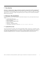
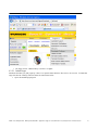
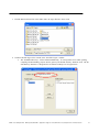
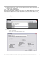
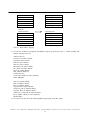
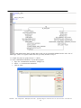
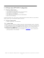
1
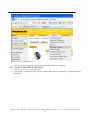
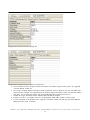
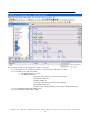
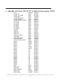
SARTUP GUIDE
BLXX-PG-EN for GE 90-30 Series
G1024
Published 8/28/2013
Content
1
2
3
4
Introduction ....................................................................................................................................................... 3
Reference Documentation ................................................................................................................................. 3
System Overview ............................................................................................................................................... 3
BL67 Configuration ............................................................................................................................................ 4
4.1
Hardware Requirements .......................................................................................................................4
4.1.1
Hardware Setup .................................................................................................................. 4
4.2
Software Requirements .........................................................................................................................5
4.2.1
IO Assistant ......................................................................................................................... 5
4.2.2
BL67 Program...................................................................................................................... 5
4.2.2.1
Install Target................................................................................................................................. 6
4.2.2.2
Create BLident CoDeSys Project ................................................................................................... 9
5 GE Fanuc Series 90™-30 PLC Configuration ..................................................................................................... 14
5.1
Hardware Requirements .....................................................................................................................14
5.2
Software Requirements .......................................................................................................................14
5.2.1
Software Setup .................................................................................................................. 14
5.2.2
Create GE Series 90™-30 PLC Project ................................................................................. 15
6 Appendix A GE Series 90™-30 PLC Variable List for program _MAIN................................................................. 19
7 Appendix B GE Series 90™-30 PLC ladder logic program _MAIN....................................................................... 21
7.1
Initialization of Communication Channels ...........................................................................................21
7.2
Read Operation ..................................................................................................................................21
7.3
Write Operation .................................................................................................................................21
7.4
Close Operation..................................................................................................................................22
7.5
Ladder Logic _MAIN Program .............................................................................................................22
TURCK 3000 Campus Drive Minneapolis, MN 55441 Application Support: 1-800-544-7769 Fax: (763) 553-0708 www.turck.com
2
1 Introduction
The purpose of this document is to guide you through the configuration of Programmable Modbus TCP/IP BL20 and
BL67 gateways and RFID modules, BLident system and integration with GE Series 90™-30 PLC. The RFID interface
logic is handled by the Programmable gateway and control, status, and data are mapped to the higher level controller,
GE Series 90™-30. Tools used to configure and program this system are CoDeSys 3S, IO Assistant, and GE Machine
Edition Logic Developer-PLC.
2 Reference Documentation
Following publications provide related information and technical description of the system components used by the
system:
• BLident Modular RFID System
• BL67 User Manual for Modbus TCP/IP
• BL67 IO User Manual
• BL20 User Manual for Modbus TCP/IP
• BL20 IO User Manual
• IOAssistant – configuration software
• TCP/IP Ethernet Commications for Series 90™ PCL User’s Manual (GFK-1541B)
3 System Overview
The system presented in this example consists of BL67 Programmable Modbus TCP/IP gateway with 2RFID-A module
and Series 90™-30 PLC. The BL67 gateway act as a Modbus TCP/IP slave and implement RFID interface internally via
Proxy Indent Block, BLident function block. Series 90™-30 PLC implement Modbus TCP/IP master functionality by
periodically polling BL67 slave device. See Diagram 3.1for graphical representation of system control flow.
TURCK 3000 Campus Drive Minneapolis, MN 55441 Application Support: 1-800-544-7769 Fax: (763) 553-0708 www.turck.com
3
Diagram 3.1: Data and control flow of BLident system and GE Series 90™-30 PLC
4 BL67 Configuration
4.1 Hardware Requirements
•
•
•
•
•
•
•
BL67 Programmable Modbus TCP/IP Gateway (BL67-PG-EN) firmware rev. 1.0.0.1 or later
RFID Module (2RFID-A)
BL67 base module (BL67-B-4M12)
RFID transceiver head TB-M18
RFID tag TW-R16-B128
Ethernet 4 pin eurofast cable
24 VDC power supply
4.1.1 Hardware Setup
1.
2.
3.
Assemble BL67 gateway with base module and RFID module.
Set the IP address of the gateway. The rotary switches should be set to a value between 000 and 254. In this
case the first three bytes of the IP address are always 192.168.1. The last byte of the IP address is set using
the rotary switches. For this example, set IP address to 192.168.1.1
Power up the programmable gateway.
TURCK 3000 Campus Drive Minneapolis, MN 55441 Application Support: 1-800-544-7769 Fax: (763) 553-0708 www.turck.com
4
4.
Push the SET button for 10 seconds to store the gateway configuration.
4.2 Software Requirements
•
•
IO Assistant Software
CoDeSys v 2.3.5.8 (www.turck-usa.com/Support/Downloads_~_Software/)
4.2.1 IO Assistant
Using IO Assistance, confirm that BL67 system is configured as displayed on Diagram 4.2.
Diagram 4.2: IO Assistant BLident system configuration
4.2.2 BL67 Program
To implement BLident system on Programmable gateway, you need to write program including BLident function
block to handle Proxy Identification with the RFID read/write heads. Following is the list of required libraries and
supplementary files to create BL67 program:
• BL67_PG_EN_Target.zip – Target file for CoDeSys
(www.turck-usa.com/Support/Downloads_~_Software/)
TURCK 3000 Campus Drive Minneapolis, MN 55441 Application Support: 1-800-544-7769 Fax: (763) 553-0708 www.turck.com
5
•
BL_ident v0.4.lib – Blident library version 0.4 or higher.
4.2.2.1 Install Target
Download the BL67_PG_EN_target.zip. There is no specific folder that these files need to be saved in. To install the
target files into the CoDeSys software follow the instructions below.
1. Open the InstallTarget program.
TURCK 3000 Campus Drive Minneapolis, MN 55441 Application Support: 1-800-544-7769 Fax: (763) 553-0708 www.turck.com
6
2.
Click on the “Open…” button.
TURCK 3000 Campus Drive Minneapolis, MN 55441 Application Support: 1-800-544-7769 Fax: (763) 553-0708 www.turck.com
7
3.
Find the BL67-PG-EN.tnf file in the folder where the target files have been saved.
4.
The BL67-PG-EN target will be located in the “Possible Targets:” window.
a. The “Installation directory:” will be filled in automatically. To avoid possible errors while opening,
compiling and downloading projects into the gateways the default directory should be used. The default directory should be C:\Program Files\3S Software\CoDeSys V2.3\Targets\Turck\.
TURCK 3000 Campus Drive Minneapolis, MN 55441 Application Support: 1-800-544-7769 Fax: (763) 553-0708 www.turck.com
8
5.
Highlight BL67-PG-EN in the “Possible Targets:” and click on “Install” button. The BL67-PG-EN target can
now be seen in the “Installed targets:
4.2.2.2 Create BLident CoDeSys Project
The following instructions will take you through the steps required to create BLident CoDeSys project. It is assumed
you are familiar with CoDeSys software to complete this instruction set. The CoDeSys software will need to be installed for the following steps. The recommended version is 2.3.5.8. The hardware will not work with versions higher
than 3.0.
1.
2.
3.
Start CoDeSys
Open a new project
a. File >> New
Select the BL67-PG-EN target
4.
Push OK
a. Use the default settings
b. NEVER change the “Byte Addressing Mode” setting
TURCK 3000 Campus Drive Minneapolis, MN 55441 Application Support: 1-800-544-7769 Fax: (763) 553-0708 www.turck.com
9
5.
6.
7.
8.
a programming language
This example project is written in LD (ladder logic)
default Name “PLC_PRG.”
PLC_PRG is similar to OB1 in Siemens. This is the program that gets executed automatically. If you
change the name, and do not do a TASK configuration, the program will not run.
b. The Type of the POU should be “Program.”
Go to Resources tab >> Library Manager and add BL_ident v0.4.lib to the list of available libraries.
Go to Resources tab >> PLC Configuration >> Configuration BL67-PG-EN >> BL67-IO[SLOT] >> Input/Output and insert 2RFID-A module
Choose
a.
Use the
a.
9.
For this example we want to be able to see BLident system status, issue commands and send and receive at
lease 1 word long register from the GE controller. To accomplish this, we need to create two input and two
output Modbus registers in the PLC Configuration.
a. Resources tab >> PLC Configuration >> Configuration BL67-PG-EN >> Modbus_Registers[SLOT]
>> Input/Output tab
b. Insert two input and two output registers by highlighting the registers and clicking the “Select>>”
button
10. The BL67-PG-EN gateway communicates with a Mobdus Master via the Modbus Registers that are created in
the PLC configuration. In the previous steps, two input and two output registers were created in the configuration. These registers were aliased as Modbus_In and Modbus_Out respectively and used in the program.
The Modbus I/O registers that are created in the PLC configuration are mapped to the PC, PLC or other Modbus masters according to the tables below.
PC or PLC Modbus
Registers
BL67-PG-EN Modbus
Registers
Inputs (Read only)
Output Registers
TURCK Inc. 3000 Campus Drive Minneapolis, MN 55441
Application Support: 1-800-544-7769 Fax: (763) 553-0708 www.turck.com
10
16384
16385
16386
16387
…
17407
Output
Output
Output
Output
…
Output
Register 0
Register 1
Register 2
Register 3
Outputs
(Read and Write)
17408
17409
17410
17411
…
18431
Input Registers
Input Register 0
Input Register 1
Input Register 2
Input Register 3
…
Input Register 1023
Register 1023
Table 4.1: BL67 Modbus Mapping
11. To associate variables in our program with Modbus registers, go to Resources tab >> Global Variables and
add the following to the list:
Channel: INT:=0;
Transceiver AT %IX4.0: BOOL;
Tag_ID AT %IX4.1: BOOL;
Read AT %IX4.2: BOOL;
Write AT %IX4.3: BOOL;
Mem_Status AT %IX4.4: BOOL;
Dev_Status AT %IX4.5: BOOL;
Reset AT %IX4.6: BOOL;
Start_Address: DINT:=0;
Length: INT:=13;
TX AT %IW3: ARRAY [0..1023] OF BYTE;
Status: DWORD;
Done AT %QX4.0: BOOL;
Busy AT %QX4.1: BOOL;
Error AT %QX4.2: BOOL;
Tag_Present AT %QX4.3: BOOL;
Transceiver_On AT %QX4.4: BOOL;
Tag_Fully_Read AT %QX4.5: BOOL;
Transceiver_Connected AT %QX4.6: BOOL;
RX AT %QW3: ARRAY [0..1023] OF BYTE;
TRLEN: DINT;
12. Go to POUs tab and create the following ladder logic program in the PLC_PRG:
TURCK Inc. 3000 Campus Drive Minneapolis, MN 55441
Application Support: 1-800-544-7769 Fax: (763) 553-0708 www.turck.com
11
Using BL_ident_RFID function block from BL_ident v0.4.lib you can accomplish full RFID interface with 1 line of
ladder logic. Notice use of global variable that were previously declared in step 11.
13. Compile the project by going to Project >> Build.
14. Verify Communication Parameters of your BL67 program.
a. Open the “Communication Parameters” dialogue box.
b. Online >> Communication Parameters
c. Click on “New”
TURCK Inc. 3000 Campus Drive Minneapolis, MN 55441
Application Support: 1-800-544-7769 Fax: (763) 553-0708 www.turck.com
12
d.
Enter a name, select “Tcp/Ip (Level 2)” and click “OK”
e.
Enter the IP Address of the gateway, change the Motorola byteorder to Yes and click “OK”
15. Login to the BL67-PG-EN gateway, download the run the project
TURCK Inc. 3000 Campus Drive Minneapolis, MN 55441
Application Support: 1-800-544-7769 Fax: (763) 553-0708 www.turck.com
13
5 GE Fanuc Series 90™-30 PLC Configuration
5.1 Hardware Requirements
•
•
•
•
•
•
CPU 5 Slot Base part # IC693CHS397
CPU 366 Module with Profibus DPV1 scanner part # IC693CPU366
Ethernet Interface TCP/IP Module part # IC693CMM321
Power Supply part # IC693PWR330
Horner SNP to RS-232 Programming Cable part # HE693SNPCBL
Ethernet Cable with RJ45 plug
Assemble all component of the system referring to standard GE operation instructions. Make sure to place Ethernet
Interface module in Slot 2 of the Main Rack (right after CPU block).
5.2 Software Requirements
•
GE Fanuc Logic Developer – PLC version 5.60
5.2.1 Software Setup
The GE Series 90™-30 PLC is going act as a Modbus TCP/IP master to BL67 Programmable gateway. As described
previously, all RFID interface logic is realized within BL67 program. Therefore, GE Series 90™-30 PLC program will
be responsible for higher level control of the BLident system. The GE Series 90™-30 PLC program will allow you to
see operational status of the BLident system, issue write and read commands, view 1 receive buffer and send 1
transmit buffer back to the BLident system.
• The project for GE Series 90™-30 PLC can be downloaded from www.turck.com website and Restored in
your Logic Developer – PLC environment.
TURCK Inc. 3000 Campus Drive Minneapolis, MN 55441
Application Support: 1-800-544-7769 Fax: (763) 553-0708 www.turck.com
14
TURCK website Download/Software
•
If you wish to write project from scratch, follow instruction set in the next subsection.
5.2.2 Create GE Series 90™-30 PLC Project
1.
2.
Create new project in Logic Developer PLC.
Setup Hardware Configuration in the Navigator window. When all done, the Hardware Configuration should
look like this:
TURCK Inc. 3000 Campus Drive Minneapolis, MN 55441
Application Support: 1-800-544-7769 Fax: (763) 553-0708 www.turck.com
15
Logic Developer PLC Hardware Configuration
3. Right click on Target and select Properties. In the Inspector window configure the Physical Port parameter.
Logic Developer PLC Target Properties in Inspector window
4.
Right click on Slot 2 (IC693CMM321) in the Navigator window and select Configure. Setup IP Address and
Subnet parameters under Settings tab to work with your network configuration. Make sure that IP Address
does not conflict with any other devices on your network. Also, configure Software Load tab parameter to
match your Physical Port settings.
TURCK Inc. 3000 Campus Drive Minneapolis, MN 55441
Application Support: 1-800-544-7769 Fax: (763) 553-0708 www.turck.com
16
Configuration of Ethernet Interface, Settings tab
Configuration of Ethernet Interface, Software Load Port tab
5. Go to Variables tab of the Navigator window and declare all variables required for the project. See Appendix
A for the detailed variable list.
6. Go to Logic->Program Blocks in Navigator window and double click on _MAIN to open the mail ladder logic
program for the controller. See Appendix B for the detailed program description. Notice, that BL67 IP Address
(192.168.1.1) is set within the program logic using COM_REQ function block (run 6 and 12).
7. Validate the Target, download it to the controller and start Run the program.
8. In order to be able to set variables in the PLC Set Programmer Mode while “Online” with the Target.
9. To issue commands to the BLident system, toggle PLC command variables TR_ON, TAG_ID, READ, WRITE,
MEM_STAT, DEV_STAT, or RESET.
TURCK Inc. 3000 Campus Drive Minneapolis, MN 55441
Application Support: 1-800-544-7769 Fax: (763) 553-0708 www.turck.com
17
PLC Command variables can be toggled while “Online” with Target
10. To turn transceiver on, set TR_ON variable to 1. Observer status of the transceiver head.
11. To write data to a tag and read it back:
a. Set RFID_INPUTS[1] to a value
b. Set WRITE variable to 1.
Present tag to the transceiver head for write operation.
Reset WRITE variable to 0.
Set READ variable to 1.
Present tag to the transceiver head for read operation.
Reset WRITE variable to 0.
Verify that value of RFID_INPUTS[1] is now equal to RFID_OUTPUTS[1]
12. To see Operational Status of the RFID system
13. See value of RFID_OUTPUTS[0] variable.
TURCK Inc. 3000 Campus Drive Minneapolis, MN 55441
Application Support: 1-800-544-7769 Fax: (763) 553-0708 www.turck.com
18
6 Appendix A GE Series 90™-30 PLC Variable List for program _MAIN
Name
CLOSE_FLT
CLOSE_FLT_WRITE
CLOSE_REQ
CLOSE_REQ_WRITE
CLOSE_SUCCESS
CLOSE_SUCCESS_WRITE
DEV_STAT
DO_CLOSE
DO_OPEN
DO_READ
DO_WRITE
ETH_READY
LAN_OK
LANIFOK
MEM_STAT
OPEN_FLT
OPEN_FLT_WRITE
OPEN_REQ
OPEN_REQ_WRITE
OPEN_SUCCESS
OPEN_SUCCESS_WRITE
R00010
R00011
R00012
R00013
R00014
R00015
R00301
R00308
R00351
R00358
R00401
R00408
R00451
R00458
R00481
R00488
R00581
R00588
READ
READ_FLT
READ_REQ
READ_SUCCESS
READ_TMR
READ_TMR[0]
TURCK Inc. 3000 Campus Drive Minneapolis, MN 55441
DataType
BOOL
BOOL
BOOL
BOOL
BOOL
BOOL
BOOL
BOOL
BOOL
BOOL
BOOL
BOOL
BOOL
BOOL
BOOL
BOOL
BOOL
BOOL
BOOL
BOOL
BOOL
WORD
WORD
WORD
INT
WORD
WORD
INT
INT
INT
INT
INT
INT
INT
INT
INT
INT
INT
INT
BOOL
BOOL
BOOL
BOOL
DWORD
DWORD
IOAddress
%M00010
%M00254
%M00009
%M00255
%M00011
%M00256
%M00142
%M00257
%M00002
%M00130
%M00129
%M00001
%I00285
%I00288
%M00141
%M00004
%M00251
%M00003
%M00252
%M00005
%M00253
%R00010
%R00011
%R00012
%R00013
%R00014
%R00015
%R00301
%R00308
%R00351
%R00358
%R00401
%R00408
%R00451
%R00458
%R00481
%R00488
%R00581
%R00588
%M00139
%M00007
%M00006
%M00008
%R00712
%R00712
Application Support: 1-800-544-7769 Fax: (763) 553-0708 www.turck.com
19
READ_TMR[1]
READ_TMR[2]
RESET
RESET_TMR
RFID_INPUTS
RFID_INPUTS[0]
RFID_INPUTS[1]
RFID_OUTPUTS
RFID_OUTPUTS[00]
RFID_OUTPUTS[01]
RFID_OUTPUTS[02]
RFID_OUTPUTS[03]
RFID_OUTPUTS[04]
RFID_OUTPUTS[05]
RFID_OUTPUTS[06]
RFID_OUTPUTS[07]
RFID_OUTPUTS[08]
RFID_OUTPUTS[09]
RFID_OUTPUTS[10]
RFID_OUTPUTS[11]
RFID_OUTPUTS[12]
TAG_ID
TR_ON
WRITE
WRITE_FLT
WRITE_REQ
WRITE_SUCCESS
WRITE_TMR
WRITE_TMR[0]
WRITE_TMR[1]
WRITE_TMR[2]
TURCK Inc. 3000 Campus Drive Minneapolis, MN 55441
DWORD
DWORD
BOOL
BOOL
WORD
WORD
WORD
WORD
WORD
WORD
WORD
WORD
WORD
WORD
WORD
WORD
WORD
WORD
WORD
WORD
WORD
BOOL
BOOL
BOOL
BOOL
BOOL
BOOL
WORD
WORD
WORD
WORD
%R00714
%R00716
%M00143
%M00250
%R00717
%R00717
%R00718
%R00700
%R00701
%R00702
%R00703
%R00704
%R00705
%R00706
%R00707
%R00708
%R00709
%R00710
%R00711
%R00712
%R00713
%M00138
%M00137
%M00140
%M00013
%M00012
%M00014
%R00726
%R00726
%R00727
%R00728
Application Support: 1-800-544-7769 Fax: (763) 553-0708 www.turck.com
20
7 Appendix B GE Series 90™-30 PLC ladder logic program _MAIN
The program _MAIN consist of four (4) sections:
1. Initialization of communication channels
2. Read operation of modbus registers from BL67
3. Write operation of modbus registers
4. Close operation of communication channels
The read and write operations are performed every scan cycle of the GE controller with 2 second delay.
7.1 Initialization of Communication Channels
The first 14 lines of the _MAIN program perform initialization of 2 communication channels: 1 for read operations and
1 for write operations. The channels are initialized using COMM_REQ command block that sends “Channel Open”
command request to GE Ethernet Interface module.
7.2 Read Operation
The next 15 through 22 lines of the _MAIN program are responsible for reading 3 Modbus registers from BL67, including RFID status bits and 2 words of the RFID receive buffer, into locally declared variable RFID_OUTPUTS. The Modbus registers read from BL67 are addressed in the table 7.2. Notice, Modbus addresses are listed with offset of 1 according to COMM_REQ command block specification.
Modbus Address in GE
Corresponding Variable in BL67
Program
16385.1
Done
16385.2
Busy
16385.3
Error
16385.4
Tag_Present
16385.5
Transceiver_On
16385.6
Tag_Fully_Read
16385.7
Transceiver_Connected
16386 - 16387
RX[0-3]
Table 7.2 Modbus Mapping of BL67 Variables to GE Input Registers
7.3 Write Operation
The next 23 through 39 lines of the _MAIN program are responsible for writing 3 Modbus registers from locally declared variable RFID_INPUTS to BL67, including RFID command bits and 2 words of RFID transfer buffer. All of the
RFID_INPUTS registers can be manipulated by the GE program logic. The Modbus registers written to BL67 are addressed in the table 7.3. Notice, Modbus addresses are listed with offset of 1 according to COMM_REQ command
block specification.
Modbus Address in GE
Corresponding Variable in BL67
Program
17409.1
Transceiver
17409.2
Tag_ID
17409.3
Read
17409.4
Write
17409.5
Mem_Status
17409.6
Dev_Status
17409.7
Reset
17410-17411
TX[0-3]
Table 7.3 Modbus Mapping of BL67 Variables to GE Output Registers
TURCK Inc. 3000 Campus Drive Minneapolis, MN 55441
Application Support: 1-800-544-7769 Fax: (763) 553-0708 www.turck.com
21
7.4 Close Operation
The last 40 through 50 lines of the _MAIN program perform channel close operation based on error condition or explicit close request, CLOSE_REQ variable. Both read and write communication channels are closed and all required
registers are cleared.
7.5 Ladder Logic _MAIN Program
TURCK Inc. 3000 Campus Drive Minneapolis, MN 55441
Application Support: 1-800-544-7769 Fax: (763) 553-0708 www.turck.com
22
1
2
Open Communication with slave device. OPEN_SUCCESS is set when channel is open for communication.
Read is done on channel 5 and write on channel 6
#FST_SCN
DO_OPEN
S
3
%S00001
LANIFOK
%M00002
ETH_READY
LAN_OK
%I00285
DO_OPEN
%M00001
OPEN_REQ
4
%I00288
ETH_READY
5
%M00001
%M00002
ETH_READY OPEN_REQ
%M00001
%M00003
OPEN_FLT
MOVE
WORD
R
%M00003
%M00004
1
0 IN
Q R00010
%R00010
6
ETH_READY OPEN_REQ
BLKMOV
INT
%M00001
BLKMOV
INT
%M00003
8 IN1
Q R00301
5 IN1
Q R00308
%R00301
%R00308
0 IN2
1 IN2
8 IN3
4 IN3
9 IN4
192 IN4
0 IN5
168 IN5
0 IN6
1 IN6
3000 IN7
1 IN7
7
ETH_READY OPEN_REQ
COMM
REQ
%M00001
%M00003
OPEN_FLT
R00301 IN
FT
S
%M00004
%R00301
2 SYSI
0 TASK
MODBUS_RFID: ModbusMaster: _MAIN
05/23/07-15:30:44
Page 1
8
ETH_READY
EQ INT
%M00001
OPEN_SUC...
R00010 IN1
Q
S
%M00005
%R00010
1 IN2
9
10
When OPEN_SUCCESS is set, open another channel (6) for write communication
ETH_READY OPEN_SUC...
OPEN_REQ...
%M00001
%M00005
%M00252
11
ETH_READY OPEN_REQ...
%M00001
OPEN_FLT...
MOVE
WORD
R
%M00252
%M00251
1
0 IN
Q R00014
%R00014
12
ETH_READY OPEN_REQ...
%M00001
BLKMOV
INT
BLKMOV
INT
%M00252
8 IN1
Q R00481
6 IN1
Q R00488
%R00481
%R00488
0 IN2
1 IN2
8 IN3
4 IN3
13 IN4
192 IN4
0 IN5
168 IN5
0 IN6
1 IN6
3000 IN7
1 IN7
MODBUS_RFID: ModbusMaster: _MAIN
05/23/07-15:30:44
Page 2
13
ETH_READY OPEN_REQ...
%M00252
%M00001
COMM
REQ
OPEN_FLT...
R00481 IN
FT
S
%M00251
%R00481
2 SYSI
0 TASK
14
ETH_READY
EQ INT
%M00001
OPEN_SUC...
R00014 IN1
Q
S
%M00253
%R00014
1 IN2
15
Start read sequence. Read 13 registers starting at address 4000 hex with 1 offset into varial RFID_OUTPUTS
16
ETH_READY READ_REQ
DO_READ
S
%M00001
%M00006
%M00130
17
ETH_READY OPEN_SUC...
DO_READ
%M00005
%M00001
DO_READ
%M00130
ONDTR
TENTHS
%M00006
READ_...
R
%R00712
%M00130
20 PV
18
ETH_READY READ_REQ
19
%M00001
DO_READ
R
%M00001
%M00006
ETH_READY READ_REQ
READ_REQ
%M00130
READ_FLT
MOVE
WORD
R
%M00006
%M00007
1
0 IN
Q R00011
%R00011
MODBUS_RFID: ModbusMaster: _MAIN
05/23/07-15:30:44
Page 3
20
ETH_READY READ_REQ
%M00001
BLKMOV
INT
BLKMOV
INT
%M00006
8 IN1
Q R00351
5 IN1
Q R00358
%R00358
%R00351
0 IN2
4 IN2
8 IN3
8 IN3
10 IN4
700 IN4
0 IN5
16385 IN5
0 IN6
3 IN6
3003 IN7
1 IN7
21
ETH_READY READ_REQ
COMM
REQ
%M00001
%M00006
READ_FLT
R00351 IN
FT
S
%M00007
%R00351
2 SYSI
0 TASK
22
ETH_READY
EQ INT
%M00001
READ_SUC...
R00011 IN1
Q
S
%M00008
%R00011
1 IN2
23
24
Start write sequence. Write 3 registers starting with address 4400 with offset of 1. RFID_INPUTS
ETH_READY WRITE_REQ
DO_WRITE
S
%M00001
%M00012
MODBUS_RFID: ModbusMaster: _MAIN
%M00129
05/23/07-15:30:44
Page 4
25
ETH_READY OPEN_SUC...
%M00253
%M00001
DO_WRITE
DO_WRITE
%M00129
ONDTR
TENTHS
WRITE_REQ
%M00012
WRITE_...
R
%R00726
%M00129
20 PV
26
ETH_READY WRITE_REQ
DO_WRITE
R
27
28
%M00001
%M00012
Write RFID commands into RFID_INPUT[0].
To set command in PLC, set appropreate resiters:TR_ON, TAG_ID, READ, WRITE, MEM_STAT, DEV_STAT, RESET
WRITE_REQ
MOVE
WORD
%M00129
%M00012
1
0 IN
Q RFID_INPU...
%R00717
29
TR_ON
WRITE_REQ
OR
WORD
%M00012
%M00137
16#0100 IN1
Q RFID_INPU...
%R00717
RFID_INPU... IN2
30
%R00717
TAG_ID
WRITE_REQ
OR
WORD
%M00012
%M00138
16#0200 IN1
Q RFID_INPU...
%R00717
RFID_INPU... IN2
31
%R00717
READ
WRITE_REQ
OR
WORD
%M00012
%M00139
16#0400 IN1
Q RFID_INPU...
%R00717
RFID_INPU... IN2
32
%R00717
WRITE
WRITE_REQ
OR
WORD
%M00012
%M00140
16#0800 IN1
Q RFID_INPU...
%R00717
RFID_INPU... IN2
%R00717
MODBUS_RFID: ModbusMaster: _MAIN
05/23/07-15:30:44
Page 5
33
WRITE_REQ MEM_STAT
OR
WORD
%M00012
%M00141
16#1000 IN1
Q RFID_INPU...
%R00717
RFID_INPU... IN2
34
%R00717
WRITE_REQ DEV_STAT
OR
WORD
%M00012
%M00142
16#2000 IN1
Q RFID_INPU...
%R00717
RFID_INPU... IN2
35
WRITE_REQ
%R00717
RESET
OR
WORD
%M00012
%M00143
16#4000 IN1
Q RFID_INPU...
%R00717
RFID_INPU... IN2
36
%R00717
ETH_READY WRITE_REQ
%M00001
WRITE_FLT
MOVE
INT
R
%M00012
%M00013
1
0 IN
Q R00013
%R00013
37
ETH_READY WRITE_REQ
%M00001
BLKMOV
INT
BLKMOV
INT
%M00012
8 IN1
Q R00451
5 IN1
Q R00458
%R00451
%R00458
0 IN2
16 IN2
8 IN3
8 IN3
12 IN4
717 IN4
0 IN5
17409 IN5
0 IN6
3 IN6
3004 IN7
1 IN7
MODBUS_RFID: ModbusMaster: _MAIN
05/23/07-15:30:44
Page 6
38
ETH_READY WRITE_REQ
COMM
REQ
%M00012
%M00001
WRITE_FLT
R00451 IN
FT
S
%M00013
%R00451
2 SYSI
0 TASK
39
ETH_READY
EQ INT
%M00001
WRITE_SU...
R00013 IN1
Q
S
%M00014
%R00013
1 IN2
40
Close channels when fault is incountered or when DO_CLOSE is set by the user
41
ETH_READY
READ_FLT
%M00001
CLOSE_REQ
%M00007
DO_CLOSE
%M00009
%M00257
42
ETH_READY CLOSE_REQ
%M00001
CLOSE_FLT
MOVE
WORD
R
%M00009
%M00010
1
0 IN
Q R00012
%R00012
MODBUS_RFID: ModbusMaster: _MAIN
05/23/07-15:30:44
Page 7
43
ETH_READY CLOSE_REQ
BLKMOV
INT
BLKMOV
INT
%M00009
%M00001
2 IN1
Q R00401
5 IN1
Q R00408
%R00408
%R00401
0 IN2
0 IN2
8 IN3
0 IN3
11 IN4
0 IN4
0 IN5
0 IN5
0 IN6
0 IN6
3001 IN7
0 IN7
44
ETH_READY CLOSE_REQ
COMM
REQ
%M00009
%M00001
CLOSE_FLT
R00401 IN
FT
S
%M00010
%R00401
2 SYSI
0 TASK
45
ETH_READY
EQ INT
%M00001
CLOSE_SU...
R00012 IN1
Q
S
%M00011
%R00012
1 IN2
46
ETH_READY
WRITE_FLT
CLOSE_RE...
S
%M00001
%M00013
DO_CLOSE
%M00255
%M00257
MODBUS_RFID: ModbusMaster: _MAIN
05/23/07-15:30:44
Page 8
47
ETH_READY CLOSE_RE...
%M00001
CLOSE_FL...
MOVE
WORD
R
%M00255
%M00254
1
0 IN
Q R00015
%R00015
48
ETH_READY CLOSE_RE...
BLKMOV
INT
BLKMOV
INT
%M00255
%M00001
2 IN1
Q R00581
6 IN1
Q R00588
%R00581
%R00588
0 IN2
0 IN2
8 IN3
0 IN3
14 IN4
0 IN4
0 IN5
0 IN5
0 IN6
0 IN6
3001 IN7
0 IN7
49
ETH_READY CLOSE_RE...
%M00255
%M00001
COMM
REQ
CLOSE_FL...
R00581 IN
FT
S
%M00254
%R00581
2 SYSI
0 TASK
50
ETH_READY
EQ INT
%M00001
CLOSE_SU...
R00015 IN1
Q
S
%M00256
%R00015
1 IN2
MODBUS_RFID: ModbusMaster: _MAIN
05/23/07-15:30:44
Page 9