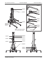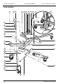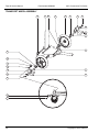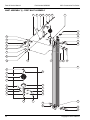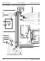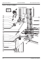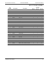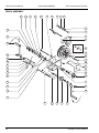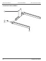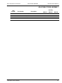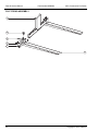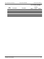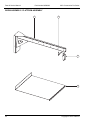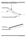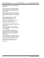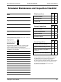
1
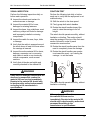
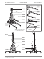
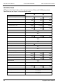
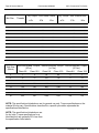
MLC PARTS & SERVICE MANUAL Part No. M00969 A Printed in the USA MLC CONSTRUCTION PRO SERIES MATERIAL LIFTS CONTENTS 1 - SAFETY Maintenance Safety It is the responsibility of the user to read, understand and obey all safety rules before attempting to perform maintenance on this equipment. This includes all rules and instructions set forth by the manufacturer, as well as any local laws and regulations governing the safe use of this equipment. It is strongly recommended that only trained and authorized personnel perform maintenance on this material lift. This manual is intended to be used in conjunction with the MLC Construction Pro Series Operator’s Manual. Failure to read, understand and obey all safety rules in both manuals may result in serious injury or death. LiftSmart is dedicated to the continuous improvement of this and all LiftSmart products. Therefore, technical information contained in this manual is subject to change without notice. Direct any questions regarding errors or discrepancies in this manual to LiftSmart. CONTACT US: LiftSmart 1370 Decision Street Suite A Vista, CA 92081 P.O. Box 4186 Oceanside, CA 92052-4186 Phone/Fax: 800.717.3079 www.liftsmart.net Patents Pending. 2 - INSPECTIONS Page 1 2 3 Daily Inspections 4 Visual Inspection 5 Function Tests 5 Quarterly Inspections 6 Cleaning the Mast Sections 7 Inspecting the Winch 7 Lubricating the Winch 7 Annual Inspections 8 Inspecting the Mast Sections 9 3 - TROUBLESHOOTING 11 4 - REPAIR 13 Removing the Base 14 Disassembling the Mast 15 Assembling the Mast 16 Replacing a Pulley 17 Additional Repairs 18 5 - PARTS 19 Decals - ANSI 20 Decals - CE 22 Base Assembly 24 Leg Assembly 26 Transport Wheel Assembly 28 Mast Assembly (I) - First Mast Assembly 30 Mast Assembly (II) - Center Mast Assembly 32 Mast Assembly (III) - Front Mast & Carriage 34 Back of the Mast Assembly 36 Winch Assembly 38 Adjustable Forks Assembly 40 Flat Forks Assembly 42 Boom Assembly / Platform Assembly 44 Pipe Cradle/Fork Extension 46 Additional Components 46 APPENDIX A: Specifications 47 APPENDIX B: Torque Requirements 49 APPENDIX C: Inspection Checklist 51 Copyright © 2012 LiftSmart. All Rights Reserved. MLC Construction Pro Series 1 Part Number M00969A Parts & Service Manual SAFETY Failure to follow all safety rules in this manual and the MLC Construction Pro Series Operator’s Manual and attached to the material lift may result in serious injury or death. Proper training is strongly recommended before attempting to perform maintenance on any mechanical device. Before performing maintenance: Read, understand and obey all safety rules and instructions in this manual and the MLC Construction Pro Series Operator’s Manual and attached to the material lift Obtain, read and obey all applicable government regulations Become familiar with the proper operation of the material lift Technicians should receive instruction before performing maintenance on the material lift Copyright © 2012 LiftSmart 1 Parts & Service Manual Part Number M00969A MLC Construction Pro Series MAINTENANCE SAFETY Follow these safety rules while performing maintenance on the material lift: ALWAYS tag a damaged material lift and remove it from service until repairs are completed according to manufacturer’s specifications. ALWAYS read, understand and obey the safety rules described in the MLC Construction Pro Operator’s Manual. ALWAYS choose a work area that is clean, well lit and properly ventilated. ALWAYS keep sparks and open flames away from flammable materials such as grease or oil. ALWAYS verify that cranes, forklifts or other lifting devices, including lifting straps or chains, are rated to support and stabilize the weight of the material lift. ALWAYS read each procedure carefully before beginning maintenance on the material lift. ALWAYS wear personal protective equipment (PPE), including protective eyewear, gloves and steel-toed shoes. ALWAYS be aware of potential hazards created by removing components from the material lift or by lifting or placing loads. ALWAYS use only tools that are in good working condition. ALWAYS use only the correct tools for the maintenance procedure. 2 Copyright © 2012 LiftSmart MLC Construction Pro Series 2 Part Number M00969A Parts & Service Manual INSPECTIONS Regularly inspecting the material lift will ensure that the equipment is operating safely and effectively. Performing all preventive/predictive maintenance procedures according to the manufacturer’s recommendations will extend the life of the material lift. While inspecting the equipment: Perform all daily, quarterly and/or annual inspections according to the manufacturer’s recommendations. Perform all quarterly and/or annual preventive/predictive maintenance procedures according to the manufacturer’s recommendations. Create a record or all inspections and/or maintenance performed using the Scheduled Maintenance and Inspection Checklist at the back of this manual. Copyright © 2012 LiftSmart 3 Parts & Service Manual Part Number M00969A MLC Construction Pro Series DAILY INSPECTIONS Perform the following inspections daily or before each use of the material lift: Verify that the MLC Construction Pro Series Operator’s Manual is located in the storage container attached to the material lift. The pages must be legible and in good condition. Perform a visual inspection of the material lift for wear or damage. Perform a function test on the material lift to verify that winch is operating correctly and that the carriage and masts rise in the correct sequence. 4 Copyright © 2012 LiftSmart MLC Construction Pro Series Part Number M00969A Parts & Service Manual VISUAL INSPECTION FUNCTION TEST Perform the following inspections daily or before each operation: Perform the following test daily or before each use to verify that the equipment is not malfunctioning: Inspect the wheels and casters for excessive wear or damage Inspect the material lift for loose, damaged or missing fasteners Inspect the base, legs, stabilizers, mast sections, pulleys and forks for damage and improperly installed or missing components Inspect the cable for wear, frays, kinks or damage Verify that the cable is wrapped around the winch drum at least four times when the carriage is lowered Inspect the entire material lift for dents, damage, excessive rust or corrosion and cracks in welds or on structurally critical components, such as mast sections Verify that all decals are legible and correctly attached to the material lift Shift the winch to the slow speed Firmly grasp both winch handles Rotate the winch handles toward the mast to raise the carriage to its full height The winch should operate smoothly, without hesitation or binding. The motion should raise the carriage to the top of the first mast section followed in order by each consecutive mast section. Rotate the winch handles away from the mast to completely lower the carriage Rotate the winch handles one quarterturn toward the mast - as if raising the carriage - to set the brake DOWN UP WARNING If any worn or damaged components are observed or suspected, remove the material lift from service immediately. Repairs to the material lift should only be performed by authorized personnel according to the manufacturer’s specifications. The winch should operate smoothly, without hesitation or binding. WARNING If the equipment malfunctions, remove the material lift from service immediately. Repairs to the material lift should only be performed by authorized personnel according to the manufacturer’s specifications. Copyright © 2012 LiftSmart 5 Parts & Service Manual Part Number M00969A MLC Construction Pro Series QUARTERLY INSPECTIONS Perform the following inspections quarterly or after every 150 hours of operation. Perform these inspections in addition to all daily inspections: Visually inspect the welds for cracks, excessive wear or corrosion. Inspect the welds on the winch mounting plate, loading wheels, Smart-Set adjustment system, base, legs, stabilizers and load lifting attachment(s). Clean the mast sections. Inspect the winch. Lubricate the winch. 6 Copyright © 2012 LiftSmart MLC Construction Pro Series Part Number M00969A Parts & Service Manual CLEANING THE MAST SECTIONS INSPECTING THE WINCH Perform the following steps to clean the mast sections: Perform the following inspections on the winch: Raise the material lift to its maximum height Inspect the brake lining plates for excessive wear Visually inspect the inner and outer channels of each mast section for debris or dirt Clean the channels of each mast section as needed using a mild cleansing agent • Inspect the reamed bushings on the shaft for excessive wear • Note: Do not lubricate the mast sections. NEVER apply an additional side load or horizontal force to a material lift that is loaded or raised. NEVER place ladders or scaffold against the material lift. Replace the brake lining plate if it is less than 1/16 inch (1.5 mm) thick Replace the reamed bushing if the wall thickness is less than 1/8 inch (3.1 mm) Inspect the winch assembly for loose, damaged or missing fasteners • Tighten or replace fasteners as needed • Tighten the 3/8-16 lock nut that attaches the reel assembly to 20 ft-lb (27 N*m) • Do not over tighten fasteners LUBRICATING THE WINCH Lubricate the gears on the following components on the winch using automotive grease: The reel assembly The ratchet wheel The primary shaft assembly The intermediate shaft assembly Lubricate the ratchet pawls with 30W oil. Lubricate the reel spacer. Copyright © 2012 LiftSmart 7 Parts & Service Manual Part Number M00969A MLC Construction Pro Series ANNUAL INSPECTIONS Perform the following inspections annually. Perform these inspections in addition to all daily and quarterly inspections: Lubricate the casters and wheels. • Add lithium-based grease into the bearings of the wheels and casters until it becomes visible at the bearing gap Inspect the mast assembly for wear. Replace the brake lining plates on the winch. • Refer to Section 5 - Parts to view an exploded view drawing of the winch Visually inspect the painted surfaces of the material lift for blisters, peels, rust, fading or corrosion. 8 Copyright © 2012 LiftSmart MLC Construction Pro Series Part Number M00969A Parts & Service Manual INSPECTING THE MAST ASSEMBLY Perform the following steps to inspect the mast assembly for wear: Tilt the material lift back and lower it onto a support so that the mast sections are parallel to the ground and the carriage is facing up. At the top of the material lift, measure the clearance between each roller wheel on a mast section and surface of the adjacent mast section. • If the clearance between the roller wheel(s) and the adjacent mast section is greater than 0.062 inches (1.57 mm), then replace the roller wheel(s). • Refer to Section 4 - Repair for instructions to disassemble the mast assembly. At the base of the material lift, measure the clearance between each roller wheel on a mast section and surface of the adjacent mast section. • If the clearance between the roller wheel(s) and the adjacent mast section is greater than 0.062 inches (1.57 mm), then replace the roller wheel(s). • Refer to Section 4 - Repair for instructions to disassemble the mast assembly. Copyright © 2012 LiftSmart 9 Parts & Service Manual Part Number M00969A MLC Construction Pro Series THIS PAGE INTENTIONALLY LEFT BLANK 10 ► Copyright © 2012 LiftSmart MLC Construction Pro Series 3 Part Number M00969A Parts & Service Manual TROUBLESHOOTING When the material lift malfunctions, use the chart on the following page to determine the cause and to correct the malfunction. To use the troubleshooting table, locate the specific complaint in the first column. Possible causes of the malfunction are listed in the second column in descending order beginning with the most likely. To correct the problem, perform the procedure listed in the third column, using the information provided in Section 4 - Repair and Section 5 - Parts as needed. When troubleshooting the material lift: Follow all of the safety rules provided in previous sections of this manual and in the MLC Construction Pro Series Operator’s Manual Use the table on the following page to determine the cause and correction of the malfunction Use Sections 4 and 5 of this manual as needed to repair the malfunction Copyright © 2012 LiftSmart 11 Parts & Service Manual Part Number M00969A COMPLAINT Mast does not sequence properly Possible CAUSE MLC Construction Pro Series CORRECTION The material lift is at or above maximum capacity Remove excess weight from the load The load is not properly centered Center the load Excessive debris on the mast sections or pulleys Clean the mast sections and pulleys The cable is binding on the pulleys Inspect the pulleys and cable; replace as needed The roller wheels are damaged Inspect the roller wheels; replace or lubricate as needed Or The roller wheels are not properly lubricated Winch operates, but the carriage will not raise Winch will not operate 12 One or more mast sections is damaged Inspect the mast sections; replace as needed The winch drum is not rotating inside the winch Inspect the winch; repair or replace as needed The cable is damaged or broken Inspect the cable for frays, kinks or other damage; replace as needed One or more pulleys is damaged Inspect the pulleys; repair or replace as needed The cable is not correctly routed through the pulleys Remove the cable; install the cable, careful to route it correctly through the pulleys The material lift is at or above maximum capacity Remove excessive weight from the load The load is not properly centered Center the load The load is obstructed Clear the obstruction or reposition the material lift The cable is binding at the winch or inside the material lift Remove the cable; The winch is damaged Inspect the winch; repair or replace the damaged component(s) as needed One or more mast sections is damaged Inspect the mast sections; repair or replace as needed Inspect the cable for frays, kinks or other damage; replace as needed Copyright © 2012 LiftSmart MLC Construction Pro Series 4 Part Number M00969A Parts & Service Manual REPAIR The following section provides instructions for the safe and proper repair of the material lift. It is the responsibility of the technician to follow these instructions. Failure to follow these instructions, as well as all safety rules in this manual and attached to the material lift may result in serious injury or death. Procedures in this section for disassembling components should be performed only until the necessary repairs can be completed. Follow the steps of the disassembly procedure in reverse order to assemble the material lift. Only trained and authorized personnel should perform maintenance or repairs on the material lift. While performing repairs: Follow all of the safety rules provided in previous sections of this manual and in the MLC Construction Pro Series Operator’s Manual Follow all instructions provided in this section Copyright © 2012 LiftSmart 13 Parts & Service Manual Part Number M00969A MLC Construction Pro Series REMOVING THE BASE Follow this procedure to remove the base from the material lift: Tilt the material lift forward to an upright position. Fully lower the carriage. Using an overhead hoist, position the material lift onto a support, such as two sawhorses, so that the mast is parallel to the ground and the carriage is facing down. Remove the load lifting attachment from the material lift. Remove the cap screws from the stabilizer mounting bracket on the back of the mast. Remove the cap screw that attaches each stabilizer to the base. Remove the stabilizers. NOTE: Keep the material lift properly supported during maintenance using an overhead hoist. Failure to support the material lift may cause the equipment to fall. Tilt the material lift back and lower it onto a support so that the legs are not touching the ground. Remove the cap screws that attach the mast brace to the base. Remove the retaining pin from each leg. Remove the base. Remove the cap screws on the base. Remove the cap screw that attaches each leg to the base. Remove the legs. 14 Copyright © 2012 LiftSmart MLC Construction Pro Series Part Number M00969A Parts & Service Manual DISASSEMBLING THE MAST Follow this procedure to disassemble the mast after the base has been removed from the material lift: Slide the carriage forward along the mast section to expose the down stop block. Remove the cap screw that attaches the rope clamp to the reel on the winch assembly. Remove the cap screw that attaches the down stop to the mast section. Remove the rope clamp from the reel. Slide the carriage back and out of the bottom of the mast section. Remove the cable from the reel on the winch assembly. After removing the carriage, repeat this procedure to remove each mast section: Tilt the material lift back and lower it onto a support so that the mast sections are parallel to the ground and the carriage is facing up. Remove the cap screw that attaches the cable anchor to the first mast section on the carriage side. Pull on the cable anchor to completely remove the cable from the mast. Copyright © 2012 LiftSmart • Slide the mast section forward to expose the down stop block. • Remove the cap screw that attaches the down stop to the mast section. • Remove the down stop. • Slide the mast section back and out of the bottom of the adjacent mast section. 15 Parts & Service Manual Part Number M00969A MLC Construction Pro Series ASSEMBLING THE MAST Follow this procedure to assemble a mast that has been disassembled: Slide the carriage into the bottom of the front mast section. Inspect the mast sections including all components and fasteners for wear or damage. Replace as needed. Hold the carriage in place and pull the cable along the length of the front mast section to the top, leaving enough slack to feed the cable into the pulleys. Clean the mast sections and rollers using a mild cleansing agent. Position the first mast section on a support so that it is parallel to the ground and open side up. Secure the mast section if it is not attached to the base. Attach all components including the rollers to the first mast section. Slide the second mast section into the first from the bottom until the mast up stop on the second mast section is even with the bottom of the first mast section. Repeat the previous step for each mast section. Each mast section should be sticking out slightly from the mast section below. Do not attach the carriage. Feed the cable into the exposed pulley at the top of the front mast section until it reaches the pulley at the bottom of the front mast section. Use needle nose pliers to feed the cable into the pulley at the bottom of the front mast section until it reaches the top of the mast section. Feed the cable into the pulley at the top of the next mast section until it reaches the pulley at the bottom of that mast section. Repeat this process to feed the cable through the pulleys at the top and bottom of each mast section. Slide each mast section forward and attach the mast down stop blocks. Attach the swaged end of the cable to the cable anchor at the top of the front mast section. Attach the cable to the reel by installing the cap screw that fastens the rope clamp to the reel. Feed the other end of the cable through the box section of the carriage and into the pulley. Use the winch to raise all columns to full height and verify that the material lift is operating correctly. Push the cable through the pulley until it comes out the back of the carriage. 16 Copyright © 2012 LiftSmart MLC Construction Pro Series Part Number M00969A Parts & Service Manual REPLACING A PULLEY Follow this procedure to replace a lifting pulley without disassembling the mast. Attach the down stop block and install the cap screw. Fully lower the carriage. Repeat this procedure as needed for each pulley to be replaced. Unwind 1 to 2 feet (about 0.5 m) of cable from the winch reel. Tilt the material lift back and lower it onto a support so that the mast is parallel to the ground and the carriage is facing up. If replacing the upper pulley on a mast section, slide the mast section above the pulley to be replaced. If replacing the lower pulley on a mast section, slide the mast section containing the pulley to be replaced. Slide the appropriate mast section forward to expose the mast down stop block. Remove the cap screw that attaches the mast down stop block to the mast section. Remove the down stop block. Slide the appropriate mast section backward until the pulley to be replaced is exposed. Remove the cap screws that attach the pulley assembly to the mast section. Remove the pulley assembly. Remove the cap screw that attaches the pulley to the pulley assembly. Remove the pulley to be replaced. Install the cable into the new pulley. Attach the pulley to the pulley assembly and install the cap screw. Attach the pulley assembly and install the cap screws. Slide the mast section forward. Copyright © 2012 LiftSmart 17 Parts & Service Manual Part Number M00969A MLC Construction Pro Series ADDITIONAL REPAIRS Refer to the exploded view drawings in this manual when performing maintenance or repairs on the material lift. ALWAYS use replacement parts provided or approved by the manufacturer. 18 Copyright © 2012 LiftSmart MLC Construction Pro Series 5 Part Number M00969A Parts & Service Manual PARTS The following section provides exploded view drawings of the major components of the material lift. These drawings are intended to assist maintenance personnel when performing maintenance or repairs on the material lift and when ordering replacement parts. Only trained and authorized personnel should perform maintenance or repairs on the material lift. When ordering replacement parts: Use the drawings on the following pages to identify the part number, description and quantity of the replacement part(s). Call LiftSmart or an authorized LiftSmart dealer to place an order. Be prepared to provide the model and serial number of the material lift as well as a shipping address. ALWAYS use only replacement parts provided or authorized by the manufacturer. NOTE: Slight variations may exist in the design of the MLC Construction Pro Series, contingent upon its date of manufacture. Whenever possible, these variations are noted in the drawings on the following pages. Call LiftSmart or an authorized LiftSmart dealer for more information. Copyright © 2012 LiftSmart 19 Parts & Service Manual Part Number M00969A MLC Construction Pro Series DECALS - ANSI Part Number Description Quantity MLC-12 MLC-18 MLC-24 M00900 Operator’s Manual Storage Container 1 1 1 M00901 WARNING - Hazards / NOTICE - Setup 1 1 1 M00905 NOTICE - Two-speed Shift 1 1 1 M00908 Use this Winch Only On The Following: 1 1 1 M00909 WARNING - Crushing Hazard 1 1 1 M00910 WARNING - No Riders 1 1 1 M00911 WARNING - Hazards 1 1 1 M00912 CAUTION - Damaged Machine Hazard 1 1 1 M00918 WARNING - Bodily Injury Hazard, Moving Parts 1 1 1 M00919 DANGER - Electrocution Hazard 2 2 2 M00920 Made in the U.S.A. 1 1 1 M00984 Standard Decal Kit, ANSI/Text (Contains all of the above) Part Number Description N/A Quantity MLC-12 MLC-18 MLC-24 2 2 M00913 LiftSmart Construction Pro Series (Cosmetic) 2 M00915 MLC-12 (Cosmetic) 2 M00916 MLC-18 (Cosmetic) M00917 MLC-24 (Cosmetic) M00921 NOTICE - Load Capacity, MLC 1 M01902 Cosmetic Decal Kit, MLC-12 1 M01903 Cosmetic Decal Kit, MLC-18 M01904 Cosmetic Decal Kit, MLC-24 Part Number M00966 2 2 1 1 1 1 Description Serial Plate, Material Lifts Quantity MLC-12 MLC-18 MLC-24 1 1 1 OPTIONAL EQUIPMENT Part Number Description M00902 WARNING - Adjustable Fork Safety (Adjustable forks only) M00903 NOTICE - Boom Setup (Boom only) M00904 WARNING - Boom Safety (Boom only) M00906 WARNING - Bodily Injury Hazard (Lifting platform only) 20 Copyright © 2012 LiftSmart MLC Construction Pro Series Part Number M00969A Parts & Service Manual M00903 M00910 M00920 M00913 M00904 M00902 M00910 M00909 M00908 M00912 M00902 M00910 M00919 M00915 or M00916 or M00917 M00910 M00906 NOTE: The forks are shown in an up/inverted position. M00918 M00911 M00921 M00905 M00966 M00910 M00900 Copyright © 2012 LiftSmart M00901 21 Parts & Service Manual Part Number M00969A MLC Construction Pro Series DECALS - CE Part Number Description Quantity MLC-12 MLC-18 MLC-24 2 2 M00913 LiftSmart Material Lift Construction Series (Cosmetic) 2 M00915 MLC-12 (Cosmetic) 2 M00916 MLC-18 (Cosmetic) M00917 MLC-24 (Cosmetic) M00920 Made in the U.S.A. 1 1 1 M00950 SYMBOL - Read the Manual 2 2 2 M00951 WARNING - No Riders - SYMBOL 2 2 2 M00952 CAUTION - Moving Parts - SYMBOL 1 1 1 M00953 DANGER - Electrocution Hazard - SYMBOL 2 2 2 M00954 Use The Winch Only On The Following: - SYMBOL 1 1 1 M00955 WARNING - Load Chart 1 1 1 M00956 WARNING - Brake Lock - SYMBOL 1 1 1 M00957 NOTICE - Two-speed Winch - SYMBOL 1 1 1 M00958 CE Mark 1 1 1 M00966 Serial Plate, Material Lifts 1 1 1 M00986 Decal Kit, MLC, CE/Symbol (Contains all decals listed above excl. M00915A, M00916A and M00917A) 22 2 2 N/A Copyright © 2012 LiftSmart MLC Construction Pro Series Part Number M00969A Parts & Service Manual M00950 M00920 M00913 M00951 M00950 M00951 M00950 M00951 M00953 M00915 or M00916 or M00917 M00950 M00951 NOTE: The forks are shown in the up/inverted position. M00950 M00952 M00951 M00955 M00957 M00954 M00956 M00966 M00951 M00950 Copyright © 2012 LiftSmart 23 Parts & Service Manual Part Number M00969A MLC Construction Pro Series BASE ASSEMBLY 9 8 6 21 18 2 8 7 16 18 16 4 5 23 21 3 18 16 1 13 18 17 7 15 18 16 10 16 12 20 9 22 19 14 24 11 Copyright © 2012 LiftSmart MLC Construction Pro Series Part Number M00969A Parts & Service Manual BASE ASSEMBLY Item Number Part Number Description Quantity MLC-12 MLC-18 MLC-24 1 M00014 Base Weldment 1 1 1 2 M00075 Stabilizer Latch Mounting Plate 1* 1 1 3 M00079 Stabilizer Brace Tube 2* 2 2 4 M00078 Stabilizer Latch Tube 2* 2 2 5 M00077 Stabilizer Latch Plate 6* 6 6 6 M00131 Stabilizer Pivot Tube 2* 2 2 7 M00700 HHCS - M12 x 80 2 + 2* 4 4 8 M00707 Washer - M12 4* 4 4 9 M00701 Hex Nut - M12 2 + 2* 4 4 10 M00034 Caster - 5” x 1 1/2” w/ Brake 2 2 2 11 M00088 Leg Locking Pin w/ Lanyard 2 2 2 12 M00071 Stabilizer Weldment 2* 2 2 13 M00713 HHCS M10 x 25 6 6 6 14 M00750 Lockwasher - 1/2” 2* 2 2 15 M00704 HHCS - M10 x 50 2* 2 2 16 M00706 Hex Nut - M10 10 + 8* 18 18 17 M00705 HHCS - M10 x 70 2* 2 2 18 M00743 Washer - M10 16 + 12* 28 28 19 M00076 Caster 1.5” x 3 1/2” - Stabilizer 2* 2 2 20 M00749 Jam Nut - 1/2-13 2* 2 2 21 M00740 HHCS - M10 x 30 4 + 4* 8 8 22 M00711 Washer - M12 - Fender 4* 4 4 23 M00052 Stabilizer Latch Spring 2* 2 2 *NOTE: Stabilizers and related components (with quantities denoted above with [*]) are optional on the MLC-12. Verify whether the MLC-12 is equipped with stabilizers before beginning maintenance or ordering replacement parts. Copyright © 2012 LiftSmart 25 Parts & Service Manual Part Number M00969A MLC Construction Pro Series LEG ASSEMBLY (2 LEGS PER MATERIAL LIFT) 7 8 1 5 6 2 4 10 8 12 3 11 12 9 26 Copyright © 2012 LiftSmart MLC Construction Pro Series Part Number M00969A Parts & Service Manual LEG ASSEMBLY Item Number Part Number Description Quantity MLC-12 MLC-18 MLC-24 1 M00284 Leg Weldment - Short 1 0 0 1 M00027 Leg Weldment - Medium 0 1 0 1 M00280 Leg Weldment - Long 0 0 1 2 M00031 Wheel - 2.5” OD x 0.75” ID 1 1 1 3 M00033 Caster - 4” x 1 1/2” - Leg 1 1 1 4 M00032 Leg Wheel Hub Bushing 1 1 1 5 M00086 Snap Ring - 0.75” 2 2 2 6 M00721 Washer - 0.76” ID x 1.25” OD 2 2 2 7 M00084 Leg Shim 2 2 2 8 M00723 FHCS - M8 x 20 4 4 4 9 M00703 Hex Nut - M8 4 4 4 10 M00713 HHCS - M10 x 25 4 4 4 11 M00706 Hex Nut - M10 4 4 4 12 M00743 Washer - M10 8 8 8 Copyright © 2012 LiftSmart 27 Parts & Service Manual Part Number M00969A MLC Construction Pro Series TRANSPORT WHEEL ASSEMBLY 10 5 10 9 3 9 2 6 10 8 7 9 4 10 11 12 1 10 7 8 6 12 13 28 Copyright © 2012 LiftSmart MLC Construction Pro Series Part Number M00969A Parts & Service Manual TRANSPORT WHEEL ASSEMBLY Item Number Part Number Description Quantity MLC-12 MLC-18 MLC-24 1 M00091 Transport Wheel Mounting Bracket - Right 1 1 1 2 M00092 Transport Wheel Mounting Bracket - Left 1 1 1 3 M00095 Transport Wheel - 10” w/ Bushings 2 2 2 4 M00096 Center Mounting Weldment 1 1 1 5 M00727 HHCS - M12 x 190 2 2 2 6 M00701 Hex Nut - M12 2 2 2 7 M00093 Transport Wheel Axle 2 2 2 8 M00094 Aluminum Tube - .75 OD x .5 ID x 3.0 2 2 2 9 M00744 Washer - 3/4” x 1-1/4” 4 4 4 10 M00707 Washer - M12 8 8 8 11 M00740 HHCS - M10 x 30 4 4 4 12 M00743 Washer - M10 8 8 8 13 M00706 Hex Nut - M10 4 4 4 Copyright © 2012 LiftSmart 29 Parts & Service Manual Part Number M00969A MLC Construction Pro Series MAST ASSEMBLY (I) - FIRST MAST ASSEMBLY 15 5 18 14 16 19 17 7 9 8 13 10 28 20 16 30 19 12 5 23 12 7 11 7 21 22 1 6 19 24 2 24 7 4 23 3 7 5 11 31 29 5 27 25 26 20 30 30 Copyright © 2012 LiftSmart MLC Construction Pro Series Part Number M00969A Parts & Service Manual MAST ASSEMBLY (I) - FIRST MAST ASSEMBLY Item Number Part Number Description Quantity MLC-12 MLC-18 MLC-24 1 M00037 Mast A 1 1 1 2 M00060 Pulley w/ Bearing 1 1 1 3 M00045 Pulley Mount - First Mast 1 1 1 4 M00048 Pulley Guard 1 1 1 8 8 8 1 1 1 5 M00740 HHCS - M10 x 30 6 M00755 HHCS - 1/2-13 x 2” 7 M00706 Hex Nut - M10 12 12 12 8 M00043 Roller 2 2 2 9 M00042 Roller Bolt - SHCS - M12 x 19 2 2 2 10 M00051 Roller Guard 2 2 2 11 M00707 Washer - M12 - Narrow 1 1 1 12 M00701 Hex Nut - M12 4 4 4 13 M00049 Mast Support Bracket - Right 1 1 1 14 M00050 Mast Support Bracket - Left 1 1 1 15 M00211 Aluminum Bushing - .75 OD x .5 ID x 4.45 2 2 2 16 M00031 Wheel - 2.5” OD x 0.75” ID 2 2 2 17 M00712 HHCS - M12 x 210 1 1 1 18 M00720 HHCS - M12 x 140 1 1 1 19 M00711 Washer - M12 - Fender 3 3 3 20 M00062 Down Stop 2 2 2 21 M00061 Up Stop 1 1 1 2 2 2 8 8 8 22 M00756 FHCS - M10 x 35 23 M00743 Washer - M10 24 M00754 1 2 Washer - 1/2”- Hardened 3 2 2 2 4 2 2 2 25 M00740 HHCS - M10 x 30 26 M00746 Lockwasher - M10 2 2 2 27 M00058 Reinforcement Block 2 2 2 28 M00210 Axle - For Colson Performa Leg Wheel 2 2 2 5 1 1 1 29 M00719 Hex Nut - 1/2-13 30 M00714 FHCS - M10 x 40 4 4 4 31 M00762 Washer - M10 - Fender 2 2 2 1 Was HHCS M12 x 40 bolt for 2011 models. Consult factory for update kit when replacing. Was FHCS - M10 x 40 for 2011 models. 3 Was different hardened washer for 2011 models (metric sized for M12 bolt and multiple washers used on each pulley assembly). Consult factory for update kit when replacing. 4 Was M10 x 20 for 2011 models. 5 Was M12 Hex Nut for 2011 models. Consult factory for update kit when replacing. 2 Copyright © 2012 LiftSmart 31 Parts & Service Manual Part Number M00969A MLC Construction Pro Series MAST ASSEMBLY (II) - CENTER MAST ASSEMBLY 15 13 10 11 3 12 8 17 4 7 16 5 6 14 2 8 19 9 1 9 19 3 2 6 8 17 7 10 16 32 4 11 10 13 15 12 5 14 18 11 Copyright © 2012 LiftSmart MLC Construction Pro Series Part Number M00969A Parts & Service Manual MAST ASSEMBLY (II) - CENTER MAST ASSEMBLY Item Number 1 2 Part Number M00038 M00060 Description Mast B Pulley w/ Bearing 1 3 M00054 Pulley Mount - 1/2-13 Thread 4 M00048 Pulley Guard 2 Quantity MLC-12 MLC-18 MLC-24 0 1 2 0 2 4 0 2 4 0 2 4 5 M00707 Washer - M12 - Narrow 0 4 8 6 M00752 HHCS - 1/2-13 x 1 1/4" 0 2 4 7 M00710 HHCS - M10 x 20 0 4 8 8 M00706 Hex Nut - M10 0 6 12 9 M00061 Up Stop 0 2 4 10 M00062 Down Stop 0 3 6 11 M00714 FHCS - M10 x 40 0 6 12 12 M00051 Roller Guard 0 4 8 13 M00042 Roller Bolt - SHCS - M12 x 19, 1/2" Shoulder 0 4 8 14 M00701 Hex Nut - M12 0 4 8 15 M00043 Roller 0 4 8 16 M00754 Washer - 1/2” - Hardened 0 2 4 17 M00746 Lockwasher - M10 0 4 8 18 M00058 Reinforcement Block 0 2 4 19 M00756 FHCS - M10 x 35 0 4 8 1 When replacing the Pulley (M00060), maintenance personnel should also replace the pulley-mount (M00054 – Pulley Mount - 1/2-13 Thread). Use red Loc-Tite on Item Number 6 and torque to 75 ft*lbs. 2 MLC series material lifts, with a serial number before 00157, use an M12 bolt to mount the pulley and a pulley mount that is tapped for metric threads. If this bolt or any portion of the pulley assembly requires replacement (including the pulley mount), replace the entire pulley assembly using service parts kit M00850. Copyright © 2012 LiftSmart 33 Parts & Service Manual Part Number M00969A MLC Construction Pro Series MAST ASSEMBLY (III) - FRONT MAST AND CARRIAGE 6 23 22 16 14 3 8 7 4 18 19 8 25 24 14 2 27 5 9 21 26 2 19 9 27 15 14 5 1 17 7 9 4 18 11 27 22 3 20 2 26 14 8 10 5 15 18 7 10 19 34 4 11 10 13 15 12 5 14 20 11 Copyright © 2012 LiftSmart MLC Construction Pro Series Part Number M00969A Parts & Service Manual MAST ASSEMBLY (III) - FRONT MAST AND CARRIAGE Item Number 1 2 Part Number M00038 M00060 Description Mast B Pulley w/ Bearing 1 2 Quantity MLC-12 MLC-18 MLC-24 1 1 1 3 3 3 3 3 3 3 M00054 Pulley Mount - 1/2-13 Thread 4 M00048 Pulley Guard 3 3 3 5 M00707 Washer - M12 - Narrow 14 14 14 6 M00716 HHCS - M12 x 30 2 2 2 7 M00710 HHCS - M10 x 20 6 6 6 8 M00706 Hex Nut - M10 7 7 7 9 M00061 Up Stop 3 3 3 10 M00062 Down Stop 3 3 3 11 M00714 FHCS - M10 x 40 6 6 6 2 2 2 3 12 M00051 Roller Guard 13 M00042 Roller Bolt - SHCS - M12 x 19, 1/2" Shoulder 6 6 6 14 M00701 Hex Nut - M12 9 9 9 15 M00043 Roller 6 6 6 16 M00065 Cable End Weldment 1 1 1 17 M00040 Carriage 1 1 1 18 M00746 Lockwasher - M10 8 8 8 19 M00754 Washer - 1/2” - Hardened 4 4 4 20 M00058 Reinforcement Block 4 4 4 21 M00715 HHCS - M12 x 40 1 1 1 22 M00740 HHCS - M10 x 30 3 3 3 23 M00743 Washer - M10 - Flat 2 2 2 24 M00753 HHCS - 1/2-13 x 1 1/2" 1 1 1 25 M00711 Washer - M12 Fender 1 1 1 26 M00752 HHCS - 1/2-13 x 1 1/4” 2 2 2 27 M00756 FHCS - M10 x 35 6 6 6 1 When replacing the Pulley (M00060), maintenance personnel should also replace the pulley-mount (M00054 – Pulley Mount - 1/2-13 Thread). Use red Loc-Tite on Item Number 6 and torque to 75 ft*lbs. 2 MLC series material lifts, with a serial number before 00157, use an M12 bolt to mount the pulley and a pulley mount that is tapped for metric threads. If this bolt or any portion of the pulley assembly requires replacement (including the pulley mount), replace the entire pulley assembly using service parts kit M00850. 3 Roller guards were used with the carriage roller wheels on early production versions of the MLC. Copyright © 2012 LiftSmart 35 Parts & Service Manual Part Number M00969A MLC Construction Pro Series BACK OF THE MAST ASSEMBLY 1 5 2 5 4 6 3 SEE WINCH ASSEMBLY 5 3 27 2 7 26 25 3 24 23 21 22 8 3 9 4 10 4 20 19 18 4 5 16 17 28 13 3 14 36 5 15 5 12 11 Copyright © 2012 LiftSmart MLC Construction Pro Series Part Number M00969A Parts & Service Manual BACK OF THE MAST ASSEMBLY Item Number Part Number Description Quantity MLC-12 MLC-18 MLC-24 1 M00106 Push Tube Weldment 1 1 1 2 M00112 Pin - Clevis - 3/8” x 3” 2 2 2 3 M00740 HHCS - M10 x 30 13 13 13 4 M00743 Washer - M10 15 15 15 5 M00706 Hex Nut - M10 14 14 14 6 M00101 Winch Mount Weldment 1 1 1 7 M00118 E-Ring - 3/8” 2 2 2 8 M00717 HHCS - M12 x 240 1 1 1 9 M00711 Washer - M12 - Fender 1 1 1 10 M00124 Spring, Hold-Down 1 1 1 11 M00724 Jam Nut, Hexagonal - M12 1 1 1 12 M00125 Tube, Aluminum - 0.5” ID x 0.75” OD x 0.875” 1 1 1 13 M00701 Hex Nut - M12 1 1 1 14 M00123 Hold Down Stop 1 1 1 15 M00723 FHCS - M8 x 20 2 2 2 16 M00703 Hex Nut - M8 2 2 2 17 M00121 Hold Down Bar 1 1 1 18 M00126 Hold Down End Hook 1 1 0 18 M00133 Hold Down End Hook, Medium 0 0 1 19 M00122 Hold Down End 1 1 1 20 M00756 HHCS - M10 x 35 1 1 1 21 M00024 Strut - Left 1 1 1 22 M00025 Strut - Right 1 1 1 23 M00110 Grip Handle 2 2 2 24 M00119 Push Nut - 0.75” 2 2 2 25 M00744 Washer - 0.76” ID x 1.25” OD 4 4 4 26 M00111 Wheel - 6” x 2” x 0.75” 2 2 2 27 M00709 Washer - 0.4” ID x 1.0 OD x 0.05” - Nylon 6 6 6 28 M00707 Washer - M12 - Narrow 1 1 1 Copyright © 2012 LiftSmart 37 Parts & Service Manual Part Number M00969A MLC Construction Pro Series WINCH ASSEMBLY 20 19 17 18 15 14 12 13 11 10 9 21 8 2 22 5 23 35 1 21 36 32 3 28 13 6 5 34 4 27 24 26 33 29 7 17 21 16 23 31 30 38 28 25 37 32 Copyright © 2012 LiftSmart MLC Construction Pro Series Part Number M00969A Parts & Service Manual WINCH ASSEMBLY Item Number Part Number Description Quantity MLC-12 MLC-18 MLC-24 1 M00800 Reel Assembly 1 1 1 2 M00801 Reel Cover 1 1 1 3 M00802 Reel Spacer 1 1 1 4 M00803 Gear Cover 1 1 1 5 M00804 Thread Forming Screw - 1/2” 1 1 1 6 M00805 Brake Spring Spacer 2 2 2 7 M00806 E-Ring - 3/4" 1 1 1 8 M00807 HHCS - 3/8-16 x 1 1/2 2 2 2 9 M00808 Washer - Flat - 3/8” 2 2 2 10 M00809 Ratchet Pawl Assembly 2 2 2 11 M00810 Ratchet Spring 2 2 2 12 M00811 Ratchet Spacer 2 2 2 13 M00812 Hex Nut 3/8-16 3 3 3 14 M00813 Reel Bolt Lock 1 1 1 15 M00814 HHCS - 3/8-16 x 5 1/2 1 1 1 16 M00815 Brake Hub Assembly 1 1 1 17 M00816 Break Lining Plate 2 2 2 18 M00817 Ratchet Wheel 1 1 1 19 M00818 Washer - Double D 1 1 1 20 M00819 Spacer 2 2 2 21 M00820 Sintered Iron Bearing 1 1 1 22 M00821 Hex Nut - 5/8-11 3 3 3 23 M00822 8” Offset Handle Assembly 0 2 2 24 M00823 Sintered Iron Bearing - 3/4" 1 1 1 25 M00824 Base 1 1 1 26 M00825 Detent Spring 2 2 2 27 M00826 Chrome Ball 2 2 2 28 M00827 Hex Nut - 1/4-20 3 3 3 29 M00828 HHCS - 1/4-20 x 1 1/2 2 2 2 30 M00829 Base Spacer 3/8 x 4 3/8 1 1 1 31 M00830 HHCS - 1/4-20 x 5 1/4 1 1 1 32 M00831 Reamed Bushing 2 2 2 33 M00832 Intermediate Shaft Assembly 1 1 1 34 M00833 Detent Block 1 1 1 35 M00834 Rope Clamp Assembly 1 1 1 36 M00835 Washer - Flat - 15/16 1 1 1 37 M00836 Primary Shaft Assembly 1 1 1 38 M00837 6” Offset Handle Assembly 2 0 0 Copyright © 2012 LiftSmart 39 Parts & Service Manual Part Number M00969A MLC Construction Pro Series ADJUSTABLE FORKS ASSEMBLY 1 3 4 2 40 Copyright © 2012 LiftSmart MLC Construction Pro Series Part Number M00969A Parts & Service Manual ADJUSTABLE FORKS ASSEMBLY Item Number Part Number Description Quantity MLC-12 MLC-18 MLC-24 1 M00191 Fork Adjustment Weldment 1 1 1 2 M00196 Adjustable Fork 2 2 2 3 M00261 Snap Pin 2 2 2 4 M00737 Fiber Washer - .625” x 0.75” 2 2 2 Copyright © 2012 LiftSmart 41 Parts & Service Manual Part Number M00969A MLC Construction Pro Series FLAT FORKS ASSEMBLY 1 3 6 4 5 2 42 Copyright © 2012 LiftSmart MLC Construction Pro Series Part Number M00969A Parts & Service Manual FLAT FORKS ASSEMBLY Item Number Part Number Description Quantity MLC-12 MLC-18 MLC-24 1 M00251 Flat Fork Main Weldment 1 1 1 2 M00255 Flat Fork Weldment 2 2 2 3 M00261 Snap Pin 2 2 2 4 M00262 Flat Fork Shim 4 4 4 5 M00723 FHCS - M8 x 20 4 4 4 6 M00703 Hex Nut - M8 4 4 4 Copyright © 2012 LiftSmart 43 Parts & Service Manual Part Number M00969A MLC Construction Pro Series BOOM ASSEMBLY / PLATFORM ASSEMBLY 1 3 2 4 44 Copyright © 2012 LiftSmart MLC Construction Pro Series Part Number M00969A Parts & Service Manual BOOM ASSEMBLY Item Number Part Number Description Quantity MLC-12 MLC-18 MLC-24 1 M00164 Boom Weldment 1 1 1 1 M00200 Clevis Weldment 1 1 1 3 M00088 Locking Pin 1 1 1 PLATFORM ASSEMBLY Item Number 4 Part Number M00160 Copyright © 2012 LiftSmart Description Platform Weldment Quantity MLC-12 MLC-18 MLC-24 1 1 1 45 Parts & Service Manual Part Number M00969A MLC Construction Pro Series PIPE CRADLE ASSEMBLY / FORK EXTENSION ASSEMBLY 2 1 3 2 3 5 4 46 Copyright © 2012 LiftSmart MLC Construction Pro Series Part Number M00969A Parts & Service Manual PIPE CRADLE ASSEMBLY Item Number Part Number Description Quantity MLC-12 MLC-18 MLC-24 1 M00271 Pipe Cradle 1 1 1 2 M00730 Wing Nut - M12 2 2 2 3 M00731 HHCS - M12 x 60 2 2 2 FORK EXTENSION ASSEMBLY Item Number Part Number Description Quantity MLC-12 MLC-18 MLC-24 4 M00163 Fork Extension Tube 1 1 1 5 M00088 Pin - Detent - 0.5” x 2.5” 1 1 1 ADDITIONAL COMPONENTS (NOT SHOWN ON DRAWINGS) Item Number Part Number Description Quantity MLC-12 MLC-18 MLC-24 M00128 Cable, 3/16” - 7 x 19 - Galvanized M00129 Cable Thimble - 3/16” 1 1 1 M00130 Cable Swage - 3/16” 1 1 1 M00186 Manual Storage Tube 1 1 1 M00187 Manual Storage Tube Cap 2 2 2 M00188 Clamp - Manual Storage Tube 2 2 2 M00747 HHCS - M6 x 25 2 2 2 M00748 Hex Nut - M6 2 2 2 M00282 Cable Assembly, MLC-12 (incl. M00128, M00129, M00130) 1 0 0 M00127 Cable Assembly, MLC-18 (incl. M00128, M00129, M00130) 0 1 0 M00286 Cable Assembly, MLC-24 (incl. M00128, M00129, M00130) 0 0 1 Copyright © 2012 LiftSmart Length Varies 47 Parts & Service Manual Part Number M00969A MLC Construction Pro Series THIS PAGE INTENTIONALLY LEFT BLANK 48 ► Copyright © 2012 LiftSmart MLC Construction Pro Series Part Number M00969A Parts & Service Manual APPENDIX A: SPECIFICATIONS Copyright © 2012 LiftSmart 49 Parts & Service Manual Part Number M00969A MLC Construction Pro Series SPECIFICATIONS LiftSmart is dedicated to the continuous improvement of this and all LiftSmart products. Specifications are subject to change without notice. MLC-12 MLC-18 MLC-24 Lift Height Standard forks - up 13 ft 3 in 4m 18 ft 6 in 5.6 m 24 ft 4 in 7.4 m Standard forks - down 11 ft 6 in 3.5 m 16 ft 10 in 5.1 m 22 ft 7 in 6.9 m Adjustable forks - up 13 ft 3 in 4m 18 ft 6 in 5.6 m 24 ft 4 in 7.4 m Adjustable forks - down 11 ft 6 in 3.5 m 16 ft 10 in 5.1 m 22 ft 7 in 6.9 m Boom 12 ft 6 in 3.8 m 17 ft 10 in 5.4 m 23 ft 7 in 7.2 m Height - stowed 7 ft 3 in 2.2 m Length - stowed 2 ft 10 in 85 cm Length - operating 5 ft 2 in 1.6 m 6 ft 1 in 1.9 m Width - stowed 30.5 in 77 cm Width - stabilizers deployed 5 ft 4 in 1.6 m Stabilizers Optional 6 ft 9 in 2.1 m Standard Forks - Length 30 in 76 cm Forks - Width - outside 23 in 58 cm Maximum load capacity 14 in (36 cm) load center 750 lb 340 kg 700 lb 318 kg 650 lb 295 kg 24 in (61 cm) load center 450 lb 205 kg 440 lb 200 kg 430 lb 195 kg 42 in (107 cm) load center 200 lb 91 kg 185 lb 84 kg 175 lb 80 kg 320 lb 145 kg 365 lb 166 kg Ground clearance 2.5 in 6 cm Load height - minimum 6 in 15 cm Weight 234 lb 106 kg Winch cranks/distance 50 High speed 4 cranks/ft 13.1 cranks/m Low speed 15 cranks/ft 49.2 cranks/m Copyright © 2012 LiftSmart MLC Construction Pro Series Part Number M00969A APPENDIX Parts & Service Manual B: TORQUE REQUIREMENTS Copyright © 2012 LiftSmart 51 Parts & Service Manual Part Number M00969A Dry Torque - SAE Grade 5 Bolts Bolt Size MLC Construction Pro Series Dry Torque - SAE Grade 8 Bolts Threads in*lb ft*lb N*m in*lb ft*lb N*m 10 24 43 5 60 7 1/4 20 96 11 144 16 5/16 18 17 23 25 34 3/8 16 30 41 45 61 7/16 14 50 68 70 95 1/2 13 75 102 110 149 9/16 12 110 149 150 204 5/8 11 150 204 220 298 3/4 10 260 353 380 515 7/8 9 430 583 600 814 1 8 640 868 900 1221 Bolt Size (Metric) Recommended Torque Recommended Torque Recommended Torque (N*m) (in*lbs) (ft*lbs) Class 8.8 Class 10.9 Class 8.8 Class 10.9 Class 8.8 Class 10.9 5 7 9 62 80 5 7 6 12 16 106 142 9 12 8 30 40 266 354 22 30 10 55 75 487 664 41 55 12 100 135 885 1195 74 100 14 160 215 1416 1903 118 159 16 245 335 2168 2965 181 247 20 480 650 4248 5753 354 479 NOTE: The specifications listed above are for general use only. Torque specifications on the material lift may vary. Specifications described for a specific procedure supersede the specifications listed above. NOTE: The specifications listed above are for dry bolts. Torque specifications for a lubricated bolt are generally 25% less than the specification listed above. 52 Copyright © 2012 LiftSmart MLC Construction Pro Series Part Number M00969A Parts & Service Manual APPENDIX C: INSPECTION CHECKLIST Copyright © 2012 LiftSmart 53 Parts & Service Manual Part Number M00969A MLC Construction Pro Series Scheduled Maintenance and Inspection Checklist Use the checklist on the following page to create a record of all scheduled inspections and/or maintenance that is performed on the material lift. Make copies of the checklist as needed and keep a permanent record of all inspections and maintenance performed on the material lift. Mark the appropriate box to indicate whether a daily, quarterly or annual inspection is being performed. When performing a quarterly inspection, also perform a daily inspection. When performing an annual inspection, always perform a quarterly inspection and a daily inspection. Mark the appropriate box beside each inspection procedure: A for acceptable or U for unacceptable. If U (Unacceptable) is marked for any inspection procedure, tag the material lift and remove it from service until repairs are completed according to manufacturer’s specifications. After making repairs to a damaged material lift, ALWAYS perform a new full inspection before returning the material lift to service. Only authorized and trained personnel should perform maintenance on the material lift. 54 Copyright © 2012 LiftSmart MLC Construction Pro Series Part Number M00969A Parts & Service Manual Scheduled Maintenance and Inspection Checklist Model Daily Inspections A U A U A U Operator’s Manual Serial Number Visual Inspection Inspection Location Function Test Inspector Name (Print) Quarterly Inspections Inspector Title Inspect the Welds Inspector Signature Date Mark the appropriate box to indicate whether a daily, quarterly or annual inspection is being performed. Clean the Mast Sections Inspect the Winch Lubricate the Winch Daily Inspection Quarterly Inspection Annual Inspection When performing a quarterly inspection, also perform a daily inspection. When performing an annual inspection, always perform a quarterly inspection and a daily inspection. Mark the appropriate box beside each inspection procedure: A for acceptable or U for unacceptable. Annual Inspections Lubricate Casters and Wheels Inspect the Mast Assembly for Wear Replace the Brake Lining Plates on the Winch NOTES: Inspect the Paint on the Material Lift If U (Unacceptable) is marked for any inspection procedure, tag the material lift and remove it from service until repairs are completed according to manufacturer’s specifications. After making repairs to a damaged material lift, ALWAYS perform a new full inspection before returning the material lift to service. Only authorized and trained personnel should perform maintenance on the material lift. Copyright © 2012 LiftSmart 55 Parts & Service Manual Part Number M00969A MLC Construction Pro Series THIS PAGE INTENTIONALLY LEFT BLANK 56 Copyright © 2012 LiftSmart NOTES: John 3:16 Part No. M00969 A Printed in the USA