1
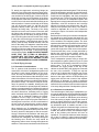
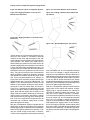
THE X-ARRAYTM INSTALL SYSTEM
X-Array Install™ - Xi
LOUDSPEAKER
SYSTEM
FLYING MANUAL
TABLE OF CONTENTS
I. INTRODUCTION ..............................................................................................................................................
1.1 The Flying Xi Loudspeaker Systems .................................................................................................... 3
II. BASIC XI RIGGING PRIMER ........................................................................................................................ 2
2.1 Anatomy of an Xi Flying System ........................................................................................................... 3
2.2 The Rigging Hardware .................................................................................................................................. 3
2.3 The Xi Flying Concept .......................................................................................................................... 7
2.3.1 Acoustical Considerations ........................................................................................................ 7
2.3.2 Practical Considerations ........................................................................................................... 7
III . ASSOCIATED RIGGING HARDWARE FOR FLYING XI LOUDSPEAKER SYSTEMS .............................. 9
3.1 Grids and Associated Hardware ........................................................................................................... 9
IV. Rigging Strength Ratings, Safety Factors and
Special ..............
Special Safety Considerations .................................................................................................................. 10
4.1 Strength Ratings and Safety Factors .................................................................................................... 9
4.2 Special Safety Considerations for Xi Loudspeaker Arrays ................................................................. 10
4.3 Special Safety Considerations for Rigging Strap Assemblies ............................................................. 12
4.3.1 Redundant Attachment Points ................................................................................................ 12
4.3.2 Special Considerations for Polyester Webbing ....................................................................... 12
4.4 Special Safety Considerations for Grid & Building Structural Supports .............................................. 12
V. RIGGING INSPECTION, MAINTENANCE AND PRECAUTIONS .................................................................
5.1 Xi System Components ...................................................................................................................... 12
5.1.1 Xi Loudspeaker Systems ........................................................................................................ 12
5.1.2 Rigging Strap Assemblies ...................................................................................................... 12
5.2 Associated Hardware ......................................................................................................................... 13
5.2.1 Grid Assembly ........................................................................................................................ 13
5.2.2 Chain Hoists ........................................................................................................................... 13
5.2.3 Building Structural Supports ................................................................................................... 13
5.2.4 Mechanical Components ....................................................................................................... 13
Appendices ..........................................................................................................................................................
A. Xi Rigging Accessories ........................................................................................................................ 14
B. References .......................................................................................................................................... 14
B.1 Acoustical References .............................................................................................................. 14
B.2 Mechanical References ............................................................................................................ 14
WARNING
This manual details general rigging practices appropriate to the sound industry, as they would apply
to the rigging of Electro-Voice X-Array Install™
Xi loudspeaker systems. It is intended to familiarize
the reader with standard rigging hardware and techniques for suspending those loudspeaker systems
overhead. Only persons with the knowledge of proper
hardware and safe rigging techniques should attempt to suspend any sound systems overhead.
Prior to suspending any Electro-Voice Xi loudspeaker
systems overhead, it is essential that the user be
familiar with the strength ratings, rigging techniques
and special safety considerations outlined in this
manual. The rigging techniques and practices recommended in this manual are, of necessity, in
general terms to accommodate the many variations
in loudspeaker arrays and rigging configurations. As
such, the user is expressly responsible for the safety
of all specific Xi loudspeaker-array designs and
rigging configurations as implemented in practice.
printing. As such the information may not be directly
applicable in other countries. Furthermore the regulations and requirements governing rigging hardware
and practices may be superseded by local regulations. It is the responsibility of the user to ensure that
any Electro-Voice loudspeaker system is suspended
overhead in accordance with all current federal,
state and local regulations.
All specific material concerning the strength ratings,
rigging techniques and safety considerations for the
Xi loudspeaker systems is based on the best available engineering information concerning the use
and limitations of the products. Electro-Voice
continually engages in testing and research and
development of its loudspeaker products. As a
result, the specifications are subject to change
without notice. It is the responsibility of the user to
ensure that any Electro-Voice loudspeaker system
is suspended overhead in accordance with the
strength ratings, rigging techniques and safety
considerations given in this applications manual
and any manual update notices. All associated nonElectro-Voice rigging hardware used for suspending
any X-Array Install™ Xi loudspeaker systems overhead is expressly the responsibility of others.
All of the general rigging material contained in this
manual is based on the best available engineering
information concerning materials and practices as
commonly recognized in the United States, and is
believed to be accurate at the time of the original
2
X-Array InstallTM Loudspeaker Systems Flying Manual
I. INTRODUCTION
ports to which the hoists are attached must be
capable of supporting such a load with a sufficient
safety factor. In permanent installations, the chain
hoists are often eliminated, with the grid assembly
being secured directly to the building structure. The
reader is referred to Chapters IV and V of this manual
for a detailed discussion of the structural strength
ratings of the Xi loudspeakers and L-track rigging
accessories, and information on how to safely suspend Xi loudspeaker systems overhead.
1.1 The Flying Xi Loudspeaker Systems
The flying versions of the X-Array Install™ loudspeaker systems all incorporate a unique two-point
flying system that consists of two lengths of heavyduty, L-track, aircraft-type rigging hardware on the
top and bottom of each enclosure. The design
allows arrays to be assembled very quickly, and
offers such flexibility in the vertical angling of the
cabinets that pull-up points are usually unnecessary. Furthermore, the cabinets may be oriented
with the rigging track on the top and bottom of the
enclosure or on the sides of the enclosure. For fire
safety and additional structural strength in both
flying orientations, top-to-bottom and side-to-side
metal straps link the rigging track assemblies inside
the enclosure. In addition, a line of flying hardware
accessories is available for use with the Xi loudspeaker systems from Sound Manufacturing, Inc.
(See Appendix A for available rigging accessories.)
II.
2.2 The Rigging Hardware
The Xi flying system utilizes the highest-tech aircraft-type hardware available for securing heavy
loads. Four pieces of heavy-duty, aircraft-type,
“L-Track” rigging hardware, specially machined extrusions of very-high-strength, aluminum-alloy material, are mounted in each enclosure. The track
pieces are secured to high-strength, aluminum-alloy
brackets that are an integral part of the Xi flying
enclosure. Enclosure dimensions and rigging track
locations are shown in Figure 2.2 for all of the Xi
loudspeaker systems.
BASIC XI RIGGING PRIMER
For attachment to the track, the GS-1B grid-strap
assembly, the LS-1B, LS-2B and LS-3B linking strap
assemblies, the RS-1B double-stud, swivel-ring fitting assembly and the RS-2B single-stud, swivelring fitting assembly are available from Sound
Manufacturing, Inc. (See Appendix A for details.)
These assemblies, shown in Figure 2.3, have been
specifically designed for optimal implementation of
the Electro-Voice L-track flying systems. The GS-1B
includes a double-stud, swivel-ring fitting on one end
for attachment to the enclosure and a safety hook on
the other end. The safety hook may be attached to
5/8-inch shackles, or may be secured directly to the
grid through a 7/8-inch diameter hole in the grid
bar-stock material. The LS-1B, LS-2B and LS-3B
have double-stud swivel-ring fillings on both ends for
linking two Xi enclosures together. The GS-1B,
LS-1B and LS-2B rigging straps utilize polyesterwebbing strap material. Polyester webbing was chosen for its tremendous strength and because of its
dynamic flexing capabilities. The force from any
sudden jolt or shift in the load is absorbed by the strap
rather than transmitted directly to the loudspeaker
enclosure. In addition, polyester webbing is a flexible
material that is easy to handle. The user is cautioned, however, that in certain permanent-installation applications, the polyester material may not
meet local fire regulations. The user is also cautioned that polyester material will deteriorate with
extended exposure to ultraviolet light (direct sunlight) or to hot, dry environments, resulting in reduced strength capability. In such instances, wire-rope
or chain assemblies must be substituted. The RS-1B
double-stud fitting and the RS-2B single-stud fitting
both attach to the Xi enclosure rigging track, and
have swivel rings that are suitable for attachment to
various standard rigging hardware. The user may
2.1 Anatomy of an Xi Flying System
A basic two-cabinet flying system is shown in Figure
2.1a, illustrating the integral components that make
up a typical Xi loudspeaker array, where the
enclosures are oriented with the rigging hardware on
the top and bottom of the enclosures. A similar twocabinet system is shown in Figure 2.1b where the
enclosures are oriented with the rigging hardware on
the sides of the enclosures. The top cabinets are the
starting points for constructing the arrays in both
examples. These cabinets are first secured to a grid
through the use of two grid straps per cabinet. (The
GS-1B grid straps are recommended.) The Xi enclosures are equipped with two pieces of track, which
have multiple positions where the grid straps may be
attached. The linear positioning of the attachment
points along the track (front-to-back) determines the
vertical angling of the enclosure. The remaining
ends of the grid straps are then secured to cross
members of a grid. The relative positioning of the
straps along the cross members of the grid (front to
back) determine the relative horizontal splay angle
between two adjacent columns of enclosures.
A second row of enclosures may be added below the
original two by utilizing linking straps that attach from
the lower track pieces of the top enclosures to the
upper track pieces of the bottom enclosures. (LS-1B,
LS-2B and LS-3B linking straps, each a different
length, are recommended.) Additional cabinets may
be hung in succession in this fashion, as long as the
load on any of the enclosures or rigging straps does
not exceed their working-load-limit rating. The loudspeaker/array/grid assembly is then raised into position by a motorized chain hoist (or hoists) of sufficient
load rating. Note that the weight of such an array can
be quite substantial and the building structural sup3
X-Array InstallTM Loudspeaker Systems Flying Manual
use the RS-1B and RS-2B to construct wire-rope or
chain rigging assemblies. In addition, the Xi enclosure rigging track will also accept the New Haven
NH32102-2 double-stud swivel-ring fillings and the
New Haven NH8192-2S or Ancra 42546-10 singlestud swivel-ring fillings.
Figure 2.1—Typical Xi Flying System
Figure 2.1b—Rigging Hardware on the Sides of the
Enclosures
Figure 2.1a—Rigging Hardware on the Top and
Bottom of the Enclosures
HOIST MOTOR
MOTOR
HOIST
HOIST MOTOR
WIRE ROPE SLING
WIRE ROPE SLING
5/8" SHACKLE
SHACKLE
5/8"
5/8"SHACKLE
SHACKLE
5/8"
GRID
GRID
GRID
GS-1B
GS-1B
GS-1B
GS-1B
LS-1B
LS-1B
LS-3B
LS-3B
4
X-Array InstallTM Loudspeaker Systems Flying Manual
Figure 2.2—Xi Dimensions, Weight, Rigging Location and Center of Gravity
Xi-1191
Xi-2153/64
Xi-2183/64
Xi-1153/64
Xi-1183/64
Xi-2123/94
Xi-1123/94
Xi-1152/64
Xi-1152/94
Xi-1122/85
System
"D"
"D"
"E"
"E"
TYP.
1"1"TYP.
"C"
"F"
"F"TYP.
TYP.
"A"
"A"
"G"
"G"
"H"
"H"
"B"
"B"
Notes:
All Linear Dimensions in Inches
All Angles in Degrees
All Weights in Pounds
Rigging Attachment Points Every
1.0 Inches Along Track
Front & Rear Rigging Locations
Shown for Double-Stud Fittings
Single-Stud Fitting Locations
Shifted Linearly +/-0.5 Inches
18.806
150
2.806
16.081
16.813
13.928
9.0
23.072
29.875
28.867
36.000
18.806
250
2.806
15.433
24.270
13.928
9.0
23.072
29.875
28.867
48.539
18.806
250
2.806
15.433
24.270
13.928
9.0
23.072
29.875
28.867
48.539
18.806
205
2.806
14.815
17.969
13.928
9.0
23.072
29.875
28.867
36.000
18.806
205
2.806
14.815
17.969
13.928
9.0
23.072
29.875
28.867
36.000
—
—
—
—
—
—
—
—
—
—
—
—
—
—
—
—
—
—
—
—
—
—
9.544
90
2.544
7.878
15.406
9.750
15.0
17.733
16.281
15.255
29.875
9.544
90
2.544
7.878
15.406
9.750
15.0
17.733
16.281
15.255
29.875
8.544
69
2.544
7.788
12.438
7.844
15.0
14.748
14.000
13.269
23.000
Dim "J"
Dim "H"
Dim "I"
Dim "H"
Dim "G"
Dim "E"
Dim "F"
Dim "D"
Dim "B"
Dim "C"
Dim "A"
Height Total Depth Side Depth Front Width Rear Width Side Angle From Bottom From Back Rear Point Front PointFront Point
Weight
Rigging Track
Center of Gravity
Enclosure
5
"I" TYP
TYP
"I"
1.896
1.896TYP.
TYP.
"J" TYP
TYP
"J"
X-Array InstallTM Loudspeaker Systems Flying Manual
with the feet located on either side (i.e., with the stud
feet positioned directly under the teeth of the track).
Release the outer locking ring. The round protrusion
on the bottom of the fitting should lock into the round
cutout in the track with the locking ring retracting to
its normal position, allowing the safety locking pin to
reappear and extend over the locking ring. If the
fitting does not lock into the track, nudge it along the
track and wiggle as necessary until it settles into
position. If the outer locking ring does not fully
retract, push the ring towards the track until the
safety pin reappears and extends over the locking
ring. When locked, the fitting will be immovable in
the track and the locking ring of the fitting may not be
lifted. To remove the fitting, reverse the procedure.
ALWAYS CHECK TO MAKE SURE THAT THE
FITTING IS SECURELY LOCKED INTO THE
TRACK, AND THAT THE SAFETY PIN IS EXTENDED OVER THE LOCKING RING BEFORE
LIFTING ANY LOUDSPEAKER ENCLOSURE
OVERHEAD.
Figure 2.3—The Xi L-Track Rigging Accessories
GB-1B Linking Strap (with Double-Stud Fitting)
LB-1B Linking Strap (with Double-Stud Fitting)
LB-2B Linking Strap (with Double-Stud Fitting)
Figure 2.4—The Double- and Single-Stud Ring Fittings
LS-3B Linking Strap (with Double-Stud Fitting)
Figure 2.4a—DoubIe-Stud Fitting
RB-1B Swivel-Ring Fitting (with Double-Stud Fitting)
LOCKING
PIN
LOCKING
RING
RS-2B Swivel-Ring Fitting (with Single-Stud Fitting)
The user is cautioned that the structural strength
ratings of the single-stud fittings are approximately
one half that of the double-stud fittings. These lower
ratings, however, are completely sufficient for suspending lighter loads overhead (for example, when
flying one or two of the smaller/lighter Xi loudspeaker systems in permanent installations), making the single-stud fittings attractive lower-cost
alternatives to the double-stud fittings. The reader is
referred to Chapters IV and V of this manual for a
detailed discussion of the structural strength ratings
of the Xi loudspeakers and L-track rigging accessories, and information on how to safely suspend
Xi loudspeaker systems overhead.
To attach the double-stud, swivel-ring fittings (as
shown in Figure 2.4a) to the enclosure rigging track,
push in the spring-loaded safety locking pin and lift
the outer locking ring over the pin. Continue to lift
the locking ring until the two studs on the bottom of
the fitting are fully exposed. Insert the two round feet
of the studs into the round cutouts in the track and
slide the fitting to the desired position. Center the
main body of the fitting over one of the track cutouts,
STUD
FEET
FITTING
BODY
Figure 2.4b—Single-Stud Fitting
LOCKING
PIN
FITTING
BODY
STUD
FOOT
6
X-Array InstallTM Loudspeaker Systems Flying Manual
To attach the single-stud, swivel-ring fittings (as
shown in Figure 2.4b) to the enclosure rigging track,
remove the safety locking pin and lift the fitting body
over the hole for the locking pin. Continue to lift the
fitting body until the stud on the bottom of the fitting
is fully exposed. Insert the round foot of the stud into
a round cutout in the track and slide the fitting to the
desired position. Center the main body of the fitting
over one of the track teeth (i.e. with the stud foot
positioned directly under one tooth of the track).
Release the fitting body. The body of the fitting
should lock into the round cutouts in the track with
the fitting body retracting to its normal position,
allowing the hole for the safety locking pin to reappear. If the fitting does not lock into the track, nudge
it along the track and wiggle as necessary until it
settles into position. If the fitting body does not fully
retract, push the body towards the track until the
hole for the safety pin reappears. Install the safety
locking pin into the hole in the shaft. When locked,
the fitting will be immovable in the track and the body
of the fitting may not be lifted. To remove the fitting,
reverse the procedure. ALWAYS CHECK TO MAKE
SURE THAT THE FITTING IS SECURELY
LOCKED INTO THE TRACK, AND THAT THE
SAFETY PIN IS INSTALLED BEFORE LIFTING
ANY LOUDSPEAKER ENCLOSURE OVERHEAD.
quality throughout the listening area. Third, the array
should be designed to achieve the required soundpressure levels throughout the audience. This also
maximizes the intelligibility and clarity throughout
the listening area. The key to achieving these three
goals is to select the Xi loudspeaker system with
appropriate coverage patterns and acoustic-output
capabilities, orient the enclosures and coverage
patterns for optimal array performance, and accurately aim the systems in the array. The reader is
referred to Appendix B.1 for a list of references
covering the topics of acoustics and loudspeaker
array design.
Because sound coming from numerous loudspeakers should arrive at any seat at the same time, the
speakers in an array should be curved as if mounted
on the outside of an imaginary sphere. The loudspeakers should be close-spaced to minimize lobing
and maximize coupling and each speaker must be
accurately aimed. The apparent source then becomes the single point at the center of the sphere.
The horizontal array curve is simply achieved by
hanging the cabinets closely spaced, aimed outward at diverging angles. Achieving the vertical
array curve is a bit more complex to obtain.
The Xi loudspeaker systems utilize a unique twopoint suspension system (shown in Figure 2.1) that
can achieve all of the design criteria for a true pointsource array. To tilt an Xi loudspeaker system
downward, the rigging straps at the top of that
cabinet are shifted along the rigging track towards
the rear of the enclosure. To align the top-rear
corner of an Xi cabinet with the bottom-rear corner
of an Xi cabinet above it, the rigging straps at the
bottom of the upper cabinet are shifted along the
rigging track until the rear corners of the adjacent
cabinets are in alignment. A number of examples
are presented in the following section that demonstrate both the mechanical and acoustical aspects
of an array design with the Xi loudspeaker systems.
2.3 The Xi Flying Concept
2.3.1 Acoustical Considerations
The Xi systems lend themselves to easy array
construction. All of the Xi loudspeaker systems use
the same L-track rigging hardware on the enclosures, and may be oriented with the rigging track
either on the top and bottom of the cabinets or on the
sides of the cabinets. All of the full-range Xi systems
have trapezoidal enclosures, enabling high-density,
point-source arrays. The horns in many of the fullrange Xi systems are rotatable, allowing the cabinets to be oriented for optimal physical installation
and the coverage pattern to be oriented for optimal
acoustic performance. Many of the Xi systems have
the same dimensions, facilitating ease of rigging
and a consistent cosmetic appearance. With grilles
in place, the Xi subwoofer systems are indistinguishable from the large Xi full-range systems,
allowing the option of either flying the subwoofers or
stacking them on the floor, or even a combination of
the two, while still preserving the uniform appearance of both the ground stack and the flown array.
2.3.2 Practical Considerations
The vertical angle of the flying Xi loudspeaker system may be adjusted by choosing different positions
of attachment along the rigging track on the cabinet.
There are a number of attachment points allowing
for a wide variety of angles. Although the center of
gravity is slightly different for each of the systems,
the balancing concept is the same. The further the
top attachment point is towards the back of the
cabinet, the greater the downward angle, as shown
in Figure 2.5. As the attachment point is moved
forward, the cabinet will have less downward angle
and, at the furthest point forward, will have an
upward tilt. This principle holds true when hanging
any of the Xi systems in either rigging orientation
(rigging track on the top and bottom, or on the sides).
When designing an Xi loudspeaker array, three
primary acoustic goals should be kept in mind. First,
the array should be designed so that the acoustic
energy is directed at the audience and away from
reflecting surfaces outside the listening area. This
maximizes the intelligibility and clarity throughout
the listening area. Second, the array should be
designed to achieve even coverage throughout the
audience. This ensures consistent levels and sound
7
X-Array InstallTM Loudspeaker Systems Flying Manual
Figure 2.5—Balancing the Xi Loudspeaker Systems
Figure 2.6—Interaction Between Flown Cabinets
Figure 2.5a—Rigging Hardware on the Top and
Bottom of the Enclosures
Figure 2.6a—Adding a Bottom Cabinet Affects the
Top Cabinet
Figure 2.5b—Rigging Hardware on the Sides of the
Enclosures
Figure 2.6b—After Readjusting the Top Cabinet
Vertical arrays are constructed by hanging Xi systems from one another in succession. Both the
curvature of the array and the angles of the individual cabinets are controlled by the rigging attachment positions. The shape of the array curve is
determined by the position on the lower track of an
already hanging cabinet from which the next cabinet
is hung, the further back the attachment point is on
the upper box, the further back the lower cabinet is
shifted and, hence, the greater the curvature of the
array. The goal is to have the back, top and bottom
edges to adjacent cabinets in alignment. Hanging
one cabinet from another affects the angle of the
first. This is best demonstrated in an example. In
Figure 2.6a, one Xi enclosure is hung so that it points
straight ahead and a second is added below. The
addition of the second enclosure causes the top
cabinet to point upward. Shifting the upper attachment point of the first cabinet back, as shown in
Figure 2.6b, counteracts the additional load and
results in the upper cabinet pointing straight ahead
again. Note that this change has no affect on the
angle of the lower cabinet. Additional Xi enclosures
may be hung in succession in this fashion, creating
a tall vertical line array (as long as the working-loadlimit of all of the mechanical components are not
exceeded and a sufficient safety factor is maintained throughout the array).
from one another (an Xi-1122 suspended beneath
an Xi-1191, for example), a longer strap would be
required to accommodate the different distances In
width between the rigging tracks. In this instance,the
LS-1 B could be employed. Another option would be
to use two RS-1B double-stud swivel-ring fittings
linked with a threaded-chain connector or a carabiner
snap hook. (The RS-2B single-stud-ring fittings could
be used in lighter-weight applications.)
With the Xi loudspeaker systems oriented with the
rigging track on the sides at the cabinets, a longer
rigging strap is required between the cabinets to
minimize the spacing between the systems. Typically, the LS-1B is used for this task. If, however,
Xi enclosures having different dimensions are hung
from one another (an Xi-1122 suspended beneath
an Xi-1191, for example), a longer strap would be
required to accommodate the different distances in
width between the rigging tracks. In this instance,
the LS-2B could be employed. Another option would
be to use two RS-1B double-stud-ring fittings linked
with a wire-rope assembly. (The RS-2B single-studring fittings could be used in lighter-weight applications.)
With the Xi loudspeaker systems oriented with the
rigging track on the top and bottom of the cabinets,
a short rigging strap is used between the cabinets to
minimize the spacing between the systems. Typically, the LS-3B is used for this task. If, however,
Xi enclosures having different dimensions are hung
8
X-Array InstallTM Loudspeaker Systems Flying Manual
There are two independent strength ratings that,
together, give a complete description of the overall
structural performance capabilities of any Xi loudspeaker system:
III. ASSOCIATED RIGGING HARDWARE
FOR FLYING XI LOUDSPEAKER
SYSTEMS
1. The working-load-limit rating for each individual rigging point; which is a function of the
rigging track mounted on the enclosure combined with the specified quick-release rigging
hardware. This rating varies as a function of the
angle of pull.
3.1 Grids and Associated Rigging Hardware
The GS-1B, LS-1B, LS-2B, LS-3B, RS-1B and
RS-2B rigging accessories described throughout
this manual for use with the flying Xi loudspeaker
systems are available from Sound Manufacturing,
Inc. (See Appendix A for details.)
Electro-Voice does not manufacture grids or any of
the other associated hardware required for suspending Xi loudspeaker arrays overhead. In the
case of both permanent-installation and touringsound applications, it is generally most efficient and
cost effective to design a support system specific to
the application, taking into account the loudspeaker
array requirements. In some permanent installations, it may even be possible in some circumstances to eliminate the grid and secure the
loudspeakers directly to the building structural supports. The sound-system designer is instructed to
evaluate each individual circumstance and design a
support system tailored to the specific application.
2. The working-load-limit rating for the overall
enclosure; which is a function of the combined
forces from multiple rigging points simultaneously
acting on the enclosure as a whole. This rating is
independent of the rigging pull angles.
WHEN SUSPENDING ANY Xi LOUDSPEAKER
SYSTEM OVERHEAD, THE WORKING-LOAD
LIMIT MUST NEVER BE EXCEEDED FOR EACH
INDIVIDUAL RIGGING POINT, AND THE WORKING-LOAD LIMIT MUST NEVER BE EXCEEDED
FOR THE OVERALL ENCLOSURE.
The user must be aware of both of the above
working-load-limit ratings at all times. An Xi loudspeaker system is only as strong as its weakest link.
In most applications, it is usually the case that one
of the working-load limits will be approached sooner
than the other. For example, if only two rigging
points are employed, the weakest link will always be
the individual rigging points and the working-load
limit for the individual rigging points will always be
the dominant factor If, however, four rigging points
are used, the weakest link may be either the overall
enclosure or the individual rigging points depending
on the angles of pull on the rigging points.
The individual rigging points on each Xi loudspeaker
system have two working-load-limit ratings, one
when used with a double-stud ring fitting (as used on
the GS-1B, LS-1B, LS-2B, LS-3B and RS-1B rigging
accessories, or with the New Haven NH32102-2
fitting), and one when used with a single-stud fitting
(as used on the RS-2B rigging accessory, or with the
New Haven NH8192-2S or Ancra 42546-10 fillings).
Two working-load-limit ratings are required because
the double-stud and single-stud fittings have different strength ratings. In addition, those strength
ratings will vary with the angle of pull relative to the
surface on which the rigging track is mounted. There
is only one working-load-limit rating for the overall
enclosure of each Xi loudspeaker system, and that
rating is independent of the angles of pull.
To aid rigging designers, the user is directed to two
companies that manufacture and sell generalized
and semi-custom rigging hardware and accessories
for flying loudspeaker systems - ATM Fly-Ware™
and Sound Manufacturing, Inc. (See Appendix A for
details on how to contact these companies.)
Attention: All associated non-Electro-Voice rigging
hardware used for suspending any X-Array Install™
(Xi) loudspeaker systems overhead is expressly the
responsibility of others.
IV. STRENGTH RATINGS, SAFETY
FACTORS AND SPECIAL SAFETY
CONSIDERATIONS
4.1 Strength Ratings and Safety Factors
Electro-Voice provides strength ratings for the
Xi loudspeaker systems in terms of the workingload-limit rating based on an 8:1 minimum safety
factor. The working-load-limit rating is defined as
the maximum allowable force that may be applied to
the mechanical component. The rated safety factor
is defined as the ratio of the ultimate-break-strength
rating to the working-load-limit rating. The ultimatebreak-strength rating represents the force applied to
a mechanical component at which the component
will structurally fail. As such, the force that would
result in a structural failure in the Xi loudspeaker
system will be at least eight times greater than the
specified working-load-limit ratings. The safety factor provides a margin of error to accommodate
normal dynamic shock loading, wear and tear on the
hardware components, etc. THE USER MUST
NEVER APPLY A LOAD TO AN Xi LOUDSPEAKER
SYSTEM THAT EXCEEDS THE WORKING-LOADLlMIT RATINGS.
Specifically, the flying Xi-1191, Xi-1183, Xi-1153,
Xi-2183 and Xi-2153 loudspeaker systems have the
following strength ratings. When used with doublestud fillings (as used on the GS-1B LS-1B, LS-2B,
LS-3B and RS-1B rigging accessories or as used
with the New Haven NH32102-2 fittings), the working-load-limit rating of each individual rigging point
is 500 pounds at a pull angle of 0° (i.e., perpendicular to the surface on which the track is mounted), 437
pounds at a pull angle of 45° and 375 pounds at a
9
X-Array InstallTM Loudspeaker Systems Flying Manual
pull angle of 90° (i.e., parallel to the surface on
which the track is mounted). When used with singlestud fittings (as used on the RS-2B rigging accessory or as used with the New Haven NH8192-2S or
Ancra 42546-10 fittings), the working-load-limit rating of each individual rigging point is 250 pounds at
any pull angle. The working-load-limit rating of the
overall enclosure is 1,000 pounds. Electro-Voice
insists that the user must never apply a load to any
Xi flying loudspeaker system that exceeds the working-load-limit rating of either the individual rigging
point or the overall enclosure. The strength ratings
of the flying Xi-1191, Xi-1183, Xi-1153, Xi-2183 and
Xi-2153 loudspeaker systems are summarized in
Figure 4.1a.
This includes the Xi enclosures, the rigging-strap
assemblies, the grid the hoist and all other mechanical components and hardware. The working-load
limits discussed throughout this manual for the
strength of the Electro-Voice Xi enclosures rigging
hardware, and the GS-1B, LS-1B, LS-2B, LS-3B,
RS-1B and RS-2B rigging accessories are based on
an 8:1 minimum safety factor. Where local regulations require safety factors greater than 8:1, ElectroVoice insists that the user must meet the required
safety factor. Where local regulations permit safety
factors less than 8:1, Electro-Voice still insists that
the working-load limit of the Xi enclosures/rigging
hardware, and the GS-1B, LS-1B, LS-2B, LS-3B,
RS-1B and RS-2B rigging accessories never be
exceeded.
Specifically, the flying Xi-1122, Xi-1152, Xi-1123
and Xi-2123 loudspeaker systems have the following strength ratings. When used with double-stud
fittings (as used on the GS-1B LS-1B LS-2B, LS-3B
and RS-1B rigging accessories or as used with the
New Haven NH32102-2 fittings), the working-loadlimit rating of each individual rigging point is 500
pounds at any pull angle. When used with singlestud fittings (as used on the RS-2B rigging accessory or as used with the New Haven NH8192-2S or
Ancra 42546-10 fittings), the working-load-limit rating of each individual rigging point is 250 pounds at
any pull angle. The working-load-limit rating of the
overall enclosure is 750 pounds. Electro-Voice
insists that the user must never apply a load to any
Xi flying loudspeaker system that exceeds the
working-load-limit rating of either the individual rigging point or the overall enclosure. The strength
ratings of the flying Xi-1122, Xi-1152, Xi-1123 and
Xi-2123 loudspeaker systems are summarized in
Figure 4.1b.
4.2 Special Safety Considerations for Xi
Loudspeaker Arrays
The techniques discussed in Chapter II for constructing arrays may be expanded upon to create
different arrays utilizing different combinations of
Xi loudspeaker systems, as long as a sufficient
safety factor is maintained. The user is reminded
that the top cabinet in an array supports the weight
of all the cabinets hung beneath it, and that the
weight distribution between the rigging points will
depend on the exact configuration. For example, the
center of gravity of the Xi-1152 loudspeaker system
is not perfectly centered but rather shifted slightly
towards the high-frequency side of the box. As a
result, when an Xi-1152 is hung sideways (i.e., with
the cabinet oriented so the rigging track is on the
sides), the load on the rigging strap on the highfrequency side of the Xi-1152 system would be
slightly higher than the load on the horn/compression-driver side. On the other hand, the load would
be distributed equally between the two rigging straps
at the top of a column of Xi-1152 systems hung with
the enclosures oriented with the rigging track on the
top and bottom. The weight distribution of any Xi
array can be calculated with the information presented in Figure 2.2. Readers unfamiliar with the
process of calculating load distributions should consult the list of references in Appendix B.2 which
cover the topics of rigging and engineering mechanics.
All associated mechanical components used with an
Xi flying system (shackles, chains, hoists, wire-rope
slings, nylon and/or polyester slings, etc.) should be
load rated for overhead lifting. All load-rated hardware will typically have its load rating displayed on
each piece in a visible location. Typical ratings are
denoted as the static-working load (SWL), or the
working-load limit (WLL). These ratings generally
assume a safety factor of 5:1; however, the user
should consult the hardware manufacturer to confirm the rating. Occasionally, the load rating is given
as the ultimate-break strength. This requires the
user to calculate the safety factor directly for a given
load. The actual safety factor for a given load is
defined as the ratio of the ultimate-break-strength
rating of a mechanical component to the actual load
applied to that component.
When arrays are constructed with columns of Xi
systems oriented with the rigging tracks on the top
and bottom of the enclosures the rigging straps
between the enclosures will not hang straight down
with a 0° vertical angle if the center-to-center spacing of the rigging attachment positions are different
from the bottom of one cabinet to the top of the
cabinet immediately beneath it. The rigging straps
will deviate from a 0° vertical angle when trapezoidal
cabinets are employed, or cabinets of differing size
are mixed in the same column. These vertical-angle
differences will result in forces (i.e., tension loads)
Electro-Voice suggests that the user maintain an
overall safety factor of at least 8:1 when implementing an Xi flying system. In other words, the ultimatebreak strength of each of the mechanical components
in the system should be at least eight times greater
than the actual force applied to those components.
10
X-Array InstallTM Loudspeaker Systems Flying Manual
Figure 4.1—Working-Load-Limit Strength Rating of the Xi Loudspeaker System
Figure 4.1b—Xi-1122, Xi-1152, Xi-1123 and Xi-2123
Figure 4.1a—Xi-1191, Xi-1183, Xi-1153, Xi-2183 and Xi-2153
11
X-Array InstallTM Loudspeaker Systems Flying Manual
in the rigging straps that are greater than the suspended weight. These increased forces are, in turn,
transmitted to the rigging track and enclosure and
must be taken into account when evaluating the
load on the mechanical components and the safety
factor of an array. The greater the angle difference
from the 0° vertical, the greater is the increase in
force above what it would be if the straps were at 0°.
Readers unfamiliar with the process of calculating
the increased load as a function of lifting angles
should consult the list of references in Appendix B.2
which cover the topics of rigging and engineering
mechanics.
4.4 Special Safety Considerations for Grid &
Building Structural Supports
When suspending loudspeaker arrays from grids or
building supports the associated rigging hardware
employed (i.e., rigging straps, slings, chains, wirerope assemblies, chains, etc.) may not hang at a 0°
vertical angle. These vertical-angle differences will
result in forces (i.e., tension loads) in that rigging
hardware that are greater than the weight suspended below. These increased forces must be
taken into account when evaluating the load on the
mechanical components and the safety factor of an
array. The greater the angle difference from the 0°
vertical, the greater is the increase in force above
what it would be if the straps were at 0°. Any users
unfamiliar with the process of calculating the increased load as a function of lifting angles should
consult the list of references in Appendix B.2 which
cover the topics of rigging and engineering
mechanics.
The user is reminded that the top cabinet of an array
supports the weight of all of the cabinets hung
beneath it. This generally results in the worst case
forces occurring at the top rigging-attachment point
of the top cabinets (including the top rigging straps).
However, if the rigging straps throughout the array
are at unusual and or extreme angles, the worstcase forces in an array may occur somewhere other
than the top rigging-attachment point of the top
cabinets.
Attention: Array details and rigging configurations
will affect the load on the building structure, the
grids, the loudspeaker systems, the rigging straps
and all associated rigging hardware. The user is
responsible for determining the loads on all of the
mechanical components throughout the loudspeaker
array, and for ensuring that the working-load limits
and resulting safety factors are not exceeded. A
qualified structural engineer should be consulted to
evaluate the design.
Attention: Array details and rigging configurations
will affect the load on the loudspeaker systems, the
rigging straps and all associated rigging hardware.
The user is responsible for determining the loads on
all of the mechanical components throughout the
loudspeaker array, and for ensuring that the working-load limits and resulting safety factors are not
exceeded. A qualified structural engineer should be
consulted to evaluate the design.
V. RIGGING INSPECTION, MAINTENANCE
AND PRECAUTION
4.3 Special Safety Considerations for Rigging
Strap Assemblies
5.1 Xi System Components
4.3.1 Redundant Attachment Points
5.1.1 Xi Loudspeaker Systems
As an added safety measure, it is suggested that the
user install a second set of grid straps from the top
rigging points of the top cabinets in an array back to
the grid (or building structural supports). These
redundant safely straps can be secured to an open
section of rigging track next to the primary grid
straps. The safety straps should have as little slack
as possible (less than one inch is preferable).
Prior to each use, inspect the loudspeaker enclosures for any cracks, deformations, missing or damaged components which could reduce enclosure
strength. Inspect the track and bracket assemblies
on the enclosures for any cracks, deformations,
missing or loose screws which could reduce the
flying hardware strength. Replace any loudspeaker
systems that are damaged or missing hardware.
Never exceed the limitations or maximum recommended load for the Xi systems.
4.3.2 Special Considerations for Polyester
Webbing
The GS-1B, LS-1B and LS-2B utilize polyester
webbing in their construction. The user is cautioned,
however, that in certain permanent installation applications, the polyester material may not meet local
fire regulations. The user is also cautioned that
polyester material will deteriorate with extended
exposure to ultraviolet light (direct sunlight) or to
hot, dry environments, resulting in reduced strength
capability. In such instances, wire-rope or chain
assemblies must be substituted.
5.1.2 Rigging Strap Assemblies
Prior to each use, inspect the webbing for cuts
abrasion, tears, knots, chemical damage, burns and
broken stitches which could reduce rigging-strapassembly strength. Inspect the rigging fittings and
hooks for any cracks, burrs, deformation, missing or
damaged components which could reduce strap
assembly strength. Replace any rigging-strap assemblies that have damaged webbing, or damaged
or missing hardware. Always double check that
each fitting on each of the rigging-strap assemblies
is securely locked into position in the track on the
12
X-Array InstallTM Loudspeaker Systems Flying Manual
Xi enclosures and that the safety locking pin is
engaged before lifting.
5.2 Associated Hardware
5.2.1 Grid Assembly
Prior to each use, inspect the grid assembly and
associated hardware for any cracks, deformations,
broken welds, corrosion, missing or damaged components which could reduce the grid assembly strength.
Replace any damaged grid assemblies. Never exceed the limitations or maximum recommended
load intended for grid assembly design.
5.2.2 Chain Hoists
Prior to each use, inspect the chain hoist and
associated hardware (including motor, if applicable)
for any cracks, deformation, broken welds, corrosion, missing or damaged components which could
reduce the hoist strength. Replace any damaged
chain hoists. Never exceed the limitations or maximum recommended load specified by the hoist
manufacturer. Always raise and lower the load slowly
and evenly, avoiding any rapid changes in speed or
shifting loads that could result in a sudden jolt to the
suspended system.
5.2.3 Building Structural Supports
Prior to each use, the strength and load-bearing
capabilities of the building structural supports should
be evaluated and certified by a professional engineer as being adequate for supporting the intended
rigging system (including the loudspeakers, grids,
chain hoists and all associated hardware). Prior to
each use, inspect the building structural supports for
any cracks, deformation, broken welds, corrosion,
missing or damaged components which could
reduce the structural strength. Damaged building
structural supports should be replaced or repaired
an recertified by a professional engineer.
5.2.4 Mechanical Components
Prior to each use, inspect all mechanical components (chain, wire ropes, slings, shackles, hooks,
fittings, etc.) for any cracks, deformation, broken
welds, slipping crimps, fraying, abrasion, knots,
corrosion chemical damage, loose screws, missing
or damaged components which would reduce the
maximum strength specified by the component
manufacturer. Replace any damaged mechanical
components.
13
X-Array InstallTM Loudspeaker Systems Flying Manual
APPENDICES
(8)
Appendix A: Xi Rigging Accessories
GS-1B, LS-1B, LS-2B, LS-3B, RS-1B and RS-2B
Xi Rigging Accessories: These rigging accessories described throughout this manual are available
from Sound Manufacturing, Inc., 3336 Primera Ave.,
Hollywood, CA 90068, USA, 213-850-5042.
B.2 Mechanical References
A brief list of references covering the topics of rigging
and engineering mechanics is presented below:
New Haven NH32102-2 and NH8192-2S Fittings:
The New Haven NH32102-2 swivel-ring, doublestud fitting and NH8192-2S swivel-ring single-stud
fitting recommended for attachment to the Xi rigging
track are available for the user to make custom
rigging attachment hardware. Sound Manufacturing, Inc., 3336 Primera Ave., Hollywood, CA 90068,
USA, 213-850-5042.
(1)
General Rigging Supplies: A wide variety of standard and specialty rigging hardware components for
both touring and permanent-installation applications
is available. Sound Manufacturing, Inc., 3336 Primera
Ave., Hollywood, CA 90068 USA, 213-850-5042 or
ATM Fly-ware™, 2100 S. Wilmington Ave., Carson,
CA 90810 USA, 310-834-5914
Appendix B
B.1 Acoustical References
A brief list of references covering the topics of acoustics and sound-system design is presented below:
(2)
(3)
(4)
of
(5)
(6)
(7)
W.E. Rossnagel, L.R. Higgins & J.A.
MacDonald, Handbook of Rigging for Construction and Industrial Operations, McGrawHill Book Company, New York, NY, USA
(1988).
A. Jensen & H. Chenoweth, Applied Engineering Mechanics, McGraw-Hill Book Co.,
New York, NY (1983).
(3)
J.O. Glerum, Stage Rigging Handbook, Southern Illinois University Press, Carbondale, IL,
USA (1987).
(4)
P. Carter, Backstage Handbook, Broadway
Press, New York, NY, USA (1988).
(5)
Wire Rope Technical Board, Wire Rope
Users Manual, American Iron and Steel Institute, Stevensville, MD, USA (1985).
(6)
ATM FIy-Ware™, ATM Fly-Ware™ Catalog
of Rigging Hardware and Supplies, ATM
Group, Inc., Carson, CA (1996).
(7)
Broderick & Bascom Rope Company, Rigger’s
Handbook, Sedalia, MO, USA (1993).
(8)
MacWhite Wire Rope Company, Catalog of
Tables, Data and Helpful Information,
Kenosha, WI, USA (1991).
(9) Acco Chain & Lifting Division, Chain Sling
User’s Manual, Acco Corporation, York,
PA, USA (1992).
(10) Newberry, W.G., Handbook for Riggers,
Newberry Investments Company, Calgary,
Alberta, Canada (1989).
(2)
Custom Rigging Strap Assemblies: Custom wirerope or webbing rigging strap assemblies that use
the New Haven NH32102-2 and NH8192-2S fittings
may be ordered. Sound Manufacturing, Inc.,
3336 Primera Ave., Hollywood, CA 90068, USA,
213-850-5042.
(1)
P.F. Fidlin & D.E. Carlson Electro-Voice, Inc.,
Comparative Performance of Directional Devices Used as Concert-Sound Loudspeaker
Array Elements,” Journal of the AES (April,
1990).
D. Davis & C. Davis, Sound System Engineering, Howard Sams & Co., Indianapolis, IN
(1987).
J. Eargle, Handbook of Sound System
Design, ELAR Publishing Co., Commack, NY
(1989).
G. Davis & R. Jones, Sound Reinforcement
Handbook, Hal Leonard Publishing Corp.,
Milwaukee, WI (1989).
L.L. Beranek, Acoustics, American Institute
Physics, Inc. New York, NY (1986).
H.F. Olson, Acoustical Engineering, Professional Audio Journals, Inc., Philadelphia, PA
(1991).
L.E. Kinsler. A.R. Frey, A.B. Coppens, & J.V.
Sanders, Fundamentals of Acoustics, John
Wiley & Sons, New York, NY (1980).
D.B. Keele, Electro-Voice, Inc., “What’s So
Sacred About Exponential Horns,” presented
at the 51St Convention of the AES (May,
1975), preprint #1038.
14
X-Array InstallTM Loudspeaker Systems Flying Manual
15
600 Cecil Street, Buchanan, MI 49107
800/234-6831, 616/695-6831, 616/695-1304 Fax
MANUAL - X-Array Install
©Telex Communications, Inc. 1998 • Litho in U.S.A.
Part Number 534993RevA — 9825