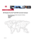
1
GA-7BESH-RH
Dual Xeon Processor Motherboard
USER’S MANUAL
XeonTM Processor Motherboard
Rev. 1001
12ME-7BESHRH-1001R
English
GA-7BESH-RH Motherboard
Table of Content
Item Checklist ......................................................................................... 4
WARNING! ............................................................................................... 4
Chapter 1 Introduction ............................................................................ 5
1.1 Features Summary ................................................................................ 5
1.2 GA-7BESH-RH Motherboard Components .......................................... 8
Chapter 2 Hardware Installation Process ............................................. 10
2-1: Installing Processor and CPU Haet Sink ........................................... 10
2-1-1: Installing CPU ....................................................................................................... 10
2-1-2: Installing Heat Sink ................................................................................................ 11
2-2: Install memory modules ..................................................................... 12
2-3: Connect ribbon cables, cabinet wires, and power supply................ 14
2-3-1 : I/O Back Panel Introduction ................................................................................ 14
2-3-2 :Connectors & Jumper Setting Introduction ......................................................... 16
Chapter 3 BIOS Setup .......................................................................... 26
Main ........................................................................................................... 28
Advanced Processor Options ........................................................................................ 31
Advanced ................................................................................................... 33
Memory Configuration ..................................................................................................... 34
PCI Configuration ............................................................................................................. 36
I/O Device Configuration ................................................................................................. 38
Advanced Chipset Control ............................................................................................. 42
Hardware Monitor ............................................................................................................ 44
Security ...................................................................................................... 47
Server ......................................................................................................... 49
System Management ...................................................................................................... 50
Console Redirection ........................................................................................................ 51
Boot ............................................................................................................ 55
Exit ............................................................................................................. 57
2
Chapter 4 Technical Reference ............................................................ 63
Block Diagram ........................................................................................... 63
Chapter 5 Driver Installation .................................................................. 64
A. Intel Chipset Software Installation Utilities ................................................................ 64
B. Intel LAN Driver Installation ...................................................................................... 66
C. ATI VGA Driver Installation ........................................................................................ 68
D. AIC-790x SCSI Driver Installation ............................................................................. 69
E. LSI RAID Driver Installation ........................................................................................ 71
F. Adaptec Storage Manager Utility Installation ............................................................ 72
G. Intel RAID Driver Installation ...................................................................................... 74
H. Matrix Storgae Manager Utility Installation ............................................................. 75
I. DirectX 9.0C Driver Installation ................................................................................... 77
Chapter 6 Appendix .............................................................................. 78
Acronyms ....................................................................................................................... 78
3
English
Table of Content
English
GA-7BESH-RH Motherboard
Item Checklist
The GA-7BESH-RH motherboard
IDE (ATA100 ) cable x 1 / Floppy cable x 1
Serial ATA cable x 4
I/O Shield Kit
CD for motherboard driver & utility
GA-7BESH-RH user’s manual
Power cable x 4
SCSI cable x 1
WARNING!
Computer motherboards and expansion cards contain very delicate Integrated Circuit (IC) chips. To
protect them against damage from static electricity, you should follow some precautions whenever you
work on your computer.
1.
Unplug your computer when working on the inside.
2.
Use a grounded wrist strap before handling computer components. If you do not have
one, touch both of your hands to a safely grounded object or to a metal object, such as
the power supply case.
Hold components by the edges and try not touch the IC chips, leads or connectors, or
other components.
Place components on a grounded antistatic pad or on the bag that came with the
components whenever the components are separated from the system.
Ensure that the ATX power supply is switched off before you plug in or remove the ATX
3.
4.
5.
power connector on the motherboard.
Installing the motherboard to the chassis…
If the motherboard has mounting holes, but they don’t line up with the holes on the base and
there are no slots to attach the spacers, do not become alarmed you can still attach the spacers to
the mounting holes. Just cut the bottom portion of the spacers (the spacer may be a little hard to
cut off, so be careful of your hands). In this way you can still attach the motherboard to the base
without worrying about short circuits. Sometimes you may need to use the plastic springs to isolate
the screw from the motherboard PCB surface, because the circuit wire may be near by the hole. Be
careful, don’t let the screw contact any printed circuit write or parts on the PCB that are near the
fixing hole, otherwise it may damage the board or cause board malfunctioning.
4
Introduction
Chapter 1 Introduction
1.1
Features Summary
Form Factor
12” x 13” EATX size form factor, 8 layers PCB
CPU
Supports Dual Intel® XeonTM processors
XeonTM Dual Core in LGA 771 socket
Supports 667/1066MHz FSB (Dempsey)
Supports 1066/1333MHz FSB (Woodcrest)
Chipset
L2 cache on-die per processor from 4M
Intel® 5000P Chipset
Memory
Intel® 6321ESB
8 x 240-pin DIMM sockets
Supports up to 32GB 533/667 memory
4 Channel memory bus
Fully Buffered DIMM (FBD) 533/667MHz
Support 512MB, 1GB, 2GB and 4GB memory
I/O Control
Expansion Slots
SCSI Controller
Single-bit Errors Correction, Multiple-bit Errors Detection
ITE Super I/O
Supports 1 PCI slots 32-Bit/33MHz (5V)
Supports 2 PCI-X slots 64-Bit/100MHz
Supports 3 PCI-Express x8 slot
Adaptec® AIC-7901 chipset supports ultra 320 SCSI channel
Mirroring supports automatic background rebuilds
Supports RAID 0 ,1, 10
Supports HOST RAID
Features LBA and Extended Interrupt 13 drive translation in
SAS RAID Controller
controller onboard BIOS
SAS daughter card supports 8 independant SAS 3.0 Gb/s with
SATA RAID Controller
Host RAID 0,1,10
Built in Intel® ESB2E with SATA RAID 0,1
On-Board Graphic
Supports 6 SATA connectors
ATI ES1000
16Mb SDRAM
5
English
GA-7BESH-RH Motherboard
On-Board Peripherals
1 ATA 100 connector
1 Floppyport supports 360K, 720K,1.2M, 1.44M and
2.88M bytes.
2 PS/2 connectors
1 Parallel port supports Normal/EPP/ECP mode
2 Serial port (COM, 1 by cable)
7 x USB 2.0 (3 by cable)
1 VGA connector
2 x LAN RJ45
Hardware Monitor
6 x SATA connectors
CPU/Power/System Fan Revolution Detect
CPU shutdown when overheat
System Voltage Detect
On-Board LAN
Build in Intel® ESB2E chipset supports dual Gigabit Ethernet ports
Supports WOL, PXE
Flexible hardware design to switch remote transactions through
IPMI interface
Hardware Monitor
Winbond 83792G controller
Enhanced features with CPU Vcore, 1.5V reference,
VCC3 (3.3V) , VBAT3V, +5VSB, CPUA/B Temperature, and
System Temperature Values viewing by
Support basic ASF remote transaction through CSA Bus with
BIOS
hardware circuit
Phoenix BIOS on 8Mb flash RAM
Special Features
Additional Features
Ehanced feature with GSMT Lite Utility
PS/2 Mouse wake up from S1 under Windows Operating System
External Modem wake up
Supports S1, S4, S5 under Windows Operating System
Wake on LAN (WOL)
Wake on Ring (WOR)
AC Recovery
Supports Console Redirection
Supports 4-pin Fan controller
6
Introduction
7
English
GA-7BESH-RH Motherboard
1.2 GA-7BESH-RH Motherboard Components
1.
Primary CPU
27.
PCI7 Slot(32bit/33MHz)
2.
3.
Secondary CPU
Intel Blackford
28.
29.
IPMI Slot
PCI-E x8 Slot
4.
5.
Intel ESB2E
Adaptec AIC-7901
30.
31.
PCI-E x8 Slot
PCI-X 3 Slot (64bit/133MHz)
6.
7.
ITE 8712F-A
BIOS Flash
32.
33.
PCI-X 2 Slot (64bit/133MHz)
PCI-E x8 Slot
8.
9.
Winbond W83792G
ATI ES1000
34.
35.
FBD DIMM A1/A2
FBDDIMM B1/B2
10.
11.
Hynix 574U
Intel LAN chip
36.
37.
FBD DIMM C1/C2
FBD DIMM D1/D2
12.
13.
IDE Connector
Front USB1 Connector
38.
39.
RJ45 LAN/USB ports
VGA Port
14.
15.
Front USB2 Connector
SCSI Connector
40.
41.
Parallel Port
COM Port
16.
17.
18.
Floppy Connector
COM2 Connector
Front Panel Connector
42.
43.
43.
PS/2 Connectors
CPU 1 FAN
CPU 2 FAN
19.
20.
IPMB1
SATA1 Connector
45.
46.
FAN 1 (System Front Fan)
FAN 2 (SystemFront Fan)
21.
22.
SATA2 Connector
SATA3 Connector
47.
48.
FAN R1 (System Rear Fan)
FAN R2 (System Rear Fan)
23.
24.
SATA4 Connector
SATA5 Connector
49.
50.
Auxiliary Power (ATX1)
Auxiliary Power (+12V)
25.
26.
SATA6 Connector
ZCR
51.
52.
Battery
ibutton**
** ibutton functions for LSI Software RAID 0,1,5,10
8
Introduction
39 40
18
38
10
9
11
31
32
29 30
28
38
34
41
42
36
33
48
47
27
19
49
17
26
16
6
50
3
5
51
7
44
37
35
43
15
24
25
4
23
22
1
2
52
13
21
20
8
14
12
46
45
9
English
GA-7BESH-RH Motherboard
Chapter 2 Hardware Installation Process
2-1: Installing Processor and CPU Haet Sink
Before installing the processor and cooling fan, adhere to the following
cautions:
1. The processor will overheat without the heatsink and/or fan, resulting in permanent
irreparable damage.
2. Never force the processor into the socket.
3. Apply thermal grease on the processor before placing cooling fan.
4. Please make sure the CPU type is supported by the motherboard.
5. If you do not match the CPU socket Pin 1 and CPU cut edge well, it will cause
improper installation. Please change the insert orientation.
2-1-1: Installing CPU
Step 1 Raise the metal locking lever on the socket.
Step 2 Remove the plastic covering on the CPU socket.
Step 3 Insert the CPU with the correct orientation. The CPU only fits in one orientation.
Step 4 Once the CPU is properly placed, please replace the plastic covering and push the metal
lever back into locked position.
10
Hardware Installation Process
2-1-2: Installing Heat Sink
Step 1.
Please apply heatsink paste on the surface of
the installed CPU.
Step 2.
Preparing heat sink installation kit.
Step 3.
Step 4.
Secure the heatsink supporting-base onto the
CPU socket on the mainboard.
Turn the mother bord to the backside. Lock the
retention module on the mother board
Make sure the position of the 4 holes on the
retention module match exactly the position on
the motherboard.
Step 5.
Attach the power connector of the heatsink to the
CPU fan header located on the motherboard.
11
English
GA-7BESH-RH Motherboard
2-2: Install memory modules
Before installing the processor and heatsink, adhere to the following warning:
When DIMM LED is ON, do not install/remove DIMM from socket.
GA-7BESH-RH has 8 dual inline memory module (DIMM) sokcets. It supports the 4 FB-DIMM
Channels Technology. The BIOS will automatically detects memory type and size during system boot.
For detail DIMM installation, please refer to the following instructions.
DIMMC1/C2
DIMMA1/A2
DIMMB1/B2
12
DIMMD1/D2
Hardware Installation Process
Installation Steps:
1. Unlock a DIMM socket by pressing the retaining clips outwards.
2. Aling a DIMM on the socket such that the notch on the DIMM exactly match the notches in the
socket.
3. Firmly insert the DIMMinto the socket until the retaining clips snap back in place.
4. Please note that each logical DIMM must be made of two identical DIMMs having the same
device size on each and the same DIMM size.
5. Reverse the installation steps when you want to remove the DIMM module.
13
English
GA-7BESH-RH Motherboard
2-3: Connect ribbon cables, cabinet wires, and power
supply
2-3-1 : I/O Back Panel Introduction
14
Hardware Installation Process
PS/2 Keyboard and PS/2 Mouse Connector
To install a PS/2 port keyboard and mouse, plug the mouse to the upper port (green) and the keyboard
to the lower port (purple).
/ /
Parallel Port / Serial Port / VGA Port
This connector supports 1 standard COM port and 1 Parallel port. Device like printer can be
connected to Parallel port ; mouse and modem etc can be connected to Serial port.
LAN Port / USB
Before you connect your device(s) into USB connector(s), please make sure your device(s) such
as USB keyboard, mouse, scanner, zip, speaker...etc. have a standard USB interface.
Also make sure your OS supports USB controller. If your OS does not support USB controller,
please contact OS vendor for possible patch or driver updated. For more information please
contact your OS or device(s) vendors.
LAN LED Description
Yellow
Name
Color
LAN
Green
Link/Activity Green
Green
Condition
ON
Description
LAN Link / no Access
BLINK
OFF
LAN Access
Idle
ON
OFF
100Mbps connection
10Mbps connection
ON
BLINK
1Gbps connection
Port identification with 1Gbps connection
Green
Green
ON
BLINK
100Mbps connection
Port identification with 10 or 100Mbps connection
-
OFF
10Mbps connection
10/100 LAN Green
Speed
GbE LAN Yellow
Speed
Yellow
15
English
GA-7BESH-RH Motherboard
2-3-2 :Connectors & Jumper Setting Introduction
15
21
14
1
22
20
4
2
23
11
9
10
7
8
6
12
16
17
5
24
18
26
25
19
3
13
1. ATX1
2. ATX3
3. IDE1 (IDE Connector)
4. FDD1 (Floppy Connector)
5. SATA 1 (SATA Connector)
6. SATA 2 (SATA Connector)
7. SATA 3 (SATA Connector)
8. SATA 4 (SATA Connector)
9. SATA 5 (SATA Connector)
10. SATA 6 (SATA Connector)
11. SCSI (SCSI Connector)
12. FAN_F1 (System Fan Connector)
13. FAN_F2 (System Fan Connector)
14. FAN_R1 (System Fan Connector)
15. FAN_R2 (System Fan Connector)
16. CPU_FAN1 (CPU 1 Fan Connector)
17. CPU_FAN2 (CPU 2 Fan Connector)
18. F_USB1 (Front USB Connector)
19. F_USB2 (Front USB Connector)
20. COM2
21. F_Panel (Front Panel Connector)
22. IPMB1
23. Battery
24. CLR_CMOS (Clear CMOS)
25. JP_REC1 (BIOS Recovery )
26. JP_PASS1(Pasword skip)
16
Connector Introduction
1) ATX1 (Auxukiary Power Connector)
12
AC power cord should only be connected to
your power supply unit after ATX power cable
1
24
13
and other related devices are firmly connected
to the mainboard.
PIN No.
Definition
1
+3.3V
2
3
+3.3V
GND
4
5
+5V
GND
6
7
+5V
GND
8
9
POK
5VSB
10
11
+12V
+12V
12
13
+3.3V
+3.3V
14
15
-12V
GND
16
17
PSON
GND
18
19
GND
GND
20
21
-5V
+5V
22
23
+5V
+5V
24
GND
2 ) ATX2 (Auxukiary +12V Power Connector)
Pin No.
1
2
3
4
5
6
7
8
This connector (ATX +12V) is used only for
CPU Core Voltage.
17
4
5
1
8
Definition
GND
GND
GND
GND
P12V_CPU
P12V_CPU
P12V_CPU
P12V_CPU
English
GA-7BESH-RH Motherboard
3 ) IDE1 (IDE Connector)
Please connect first harddisk to IDE1. The red stripe of the ribbon cable must be the same side with
the Pin1.
39
40
1
2
4 ) FDD1 (Floppy Connector)
Please connect the floppy drive ribbon cables to FDD. It supports 720K,1.2M,1.44M and
2.88Mbytes floppy disk types. The red stripe of the ribbon cable must be the same side with the
Pin1.
2 1
34 33
18
Connector Introduction
5/ 6/ 7/ 8/ 9/ 10 ) SATA 1~6 (Serial ATA Connectors)
You can connect the Serial ATA device to this connector, it provides you high speed transfer rates
(150MB/sec).
SATA6
SATA5
1
7
Pin No.
1
2
3
4
5
6
7
Definition
GND
TXP
TXN
GND
RXN
RXP
GND
SATA1 SATA3
SATA2
SATA4
11) SCSI 1 (SCSI Connector)
You can connect all major SCSI peripherals to this connector. Ultra320 SCSI technology is
compatible with Ultra160, Ultra2, Ultra Wide and all other previous-generation SCSI devices. The
data transfer rate is up to 320 MB/sec per channel. Only compatible with Win 2000/XP/NT.
19
English
GA-7BESH-RH Motherboard
12/ 13/ 14/ 15 ) FAN 1/2/3 (System Front and Rear Fan Connectors)
This connector allows you to link with the cooling fan on the system case to lower the system
temperature. These connectors are for system use only.
FAN_R1&R2
1
Pin No.
1
2
3
4
1
Definition
GND
12V
Sense
Control
FAN_F2
FAN_F1
16/ 17 ) CPU1/2_FAN (CPU Fan Connectors)
Please note, a proper installation of the CPU cooler is essential to prevent the CPU from running
under abnormal condition or damaged by overheating.The CPU fan connector supports Max. current
up to 1A .
1
1
CPU1 FAN
CPU2 FAN
20
Pin No.
1
2
3
4
Definition
GND
12V
Sense
Control
Connector Introduction
18/ 19 ) F_USB1/2 (Front USB Connectors)
Be careful with the polarity of the front USB connector. Check the pin assignment carefully while
you connect the front USB cable, incorrect connection between the cable and connector will make
the device unable to work or even damage it. For optional front USB cable, please contact your
local dealer.
1 2
9 10
Pin No.
1
Definition
Power
2
3
Power
USB Dx-
4
5
USB DyUSB Dx+
6
7
USB Dy+
GND
8
9
GND
No Pin
10
NC
F_USB1
F_USB2
20 ) COM2
2
10 9
21
Pin No.
1
2
3
4
5
6
7
8
9
10
Definition
DCDSIN2
SOUT2
DTR2GND
DSR2RTS2CTS2RI2NC
English
GA-7BESH-RH Motherboard
21 ) F_Panel (2X12 Pins Front Panel connector)
Please connect the power LED, PC speaker, reset switch and power switch of your chassis
front panel to the F_PANEL connector according to the pin assignment above.
1 2
23 24
Pin No.
1.
2.
3.
4.
5.
6.
7.
8.
9.
10.
11.
12.
13.
14.
15.
16.
17.
18.
19.
20.
21.
22.
23.
24.
Signal Name
PWLED+
5VSB
KEY
ID_LED+
PWLEDID_LEDHD+
F_SYSRDY
HDF_SYSTATUS
PWB+
L1_ACT
PWB+_GND
L1_LNKRST_BTNSENSOR_SDA
RST_BTN_GND
SENSOR_SCL
ID_SWCASE_OPENID_SW-_GND
L2_ACT
NMI_SWL2_LNK-
Description
Power LED Signal anode (+)
P5VStand By Power
Pin Removed
ID LED Signal anode (+)
Power LED Signal cathode(-)
ID LED Signal cathode(-)
Hard Disk LED Signal anode (+)
System Fan Fail LED Signal
Hard Disk LED Signal cathode(-)
System Status LED Signal
Power Button Signal anode (+)
LAN1 access LED Signal
Power Button Ground
LAN1 linked LED Signal cathode(-)
Reset Button cathode(-)
SMBus Data
Reset Button Ground
SMBus Clock
ID Switch Signal cathode(-)
Chassis intrusion Signal
ID Switch Ground
LAN2 access LED Signal
NMI Switch cathode(-)
LAN2 linked LED Signal cathode(-)
22
Connector Introduction
22 ) IPMB1
1
Pin No.
1
2
3
Definition
IPMB_SDA
GND
IPMB_SCL
23 ) Battery
CAUTION
Danger of explosion if battery is incorrectly
replaced.
Replace only with the same or equivalent
type recommended by the manufacturer.
Dispose of used batteries according to the
If you want to erase CMOS...
1.Turn OFF the computer and unplug the power cord.
2.Remove the battery, wait for 30 second.
3.Re-install the battery.
4.Plug the power cord and turn ON the computer.
23
manufacturer’s instructions.
English
GA-7BESH-RH Motherboard
24 ) CLR_CMOS1 (Clear CMOS Function)
You may clear the CMOS data to its default values by this jumper.
Default value doesn’t include the “Shunter” to prevent from improper use this jumper. To
clear CMOS, temporarily short 1-2 pin.
1
1-2 close: Normal (Default)
1
2-3 close: Clear CMOS
25 ) JP_REC1 ( BIOS Recovery Function)
Open: Enable BIOS Recovery function.
Short: Disable this function. (Default)
Please remove the jumper when system access recovery flopp disk.
24
Connector Introduction
26 ) JP_PASS1 (Password Disable Function)
Open: Normal (Default)
Short: Clear Password
Please remove the jumper when system reboot next time.
25
GA-7BESH-RH Motherboard
Chapter 3 BIOS Setup
BIOS Setup is an overview of the BIOS Setup Program. The program that allows users to modify the
basic system configuration. This type of information is stored in battery-backed CMOS RAM so that it
retains the Setup information when the power is turned off.
ENTERINGSETUP
Power ON the computer and press <F2> immediately will allow you to enter Setup.
CONTROLKEYS
<Ç>
Move to previous item
<È>
Move to next item
<Å>
Move to the item in the left hand
<Æ>
Move to the item in the right hand
<Esc>
Main Menu - Quit and not save changes into CMOS Status Page Setup Menu and
Option Page Setup Menu - Exit current page and return to Main Menu
<+/PgUp> Increase the numeric value or make changes
<-/PgDn>
Decrease the numeric value or make changes
<F1>
General help, only for Status Page Setup Menu and Option Page Setup Menu
<F2>
Reserved
<F3>
Reserved
<F4>
Reserved
<F6>
Reserved
<F7>
Reserved
<F8>
Reserved
<F9>
Load the Optimized Defaults
<F10>
Save all the CMOS changes, only for Main Menu
26
BIOS Setup
GETTINGHELP
Main Menu
The on-line description of the highlighted setup function is displayed at the bottom of the screen.
Status Page Setup Menu / Option Page Setup Menu
Press F1 to pop up a small help window that describes the appropriate keys to use and the
possible selections for the highlighted item. To exit the Help Window press <Esc>.
z
Main
This setup page includes all the items in standard compatible BIOS.
z
Advanced
This setup page includes all the items of AMI special enhanced features.
(ex: Auto detect fan and temperature status, automatically configure hard disk parameters.)
z
Security
Change, set, or disable password. It allows you to limit access the system and setup.
z
Server
Server additional features enabled/disabled setup menus.
z
Boot
This setup page include all the items of first boot function features.
z
Exit
There are five optionsin this selection: Exit Saving Changes, Exit Discarding Changes, Load
Optimal Defaults, Load Failsafe Defaults, and Discard Changes.
27
GA-7BESH-RH Motherboard
Main
Once you enter Phoenix BIOS Setup Utility, the Main Menu (Figure 1) will appear on the screen. Use
arrow keys to select among the items and press <Enter> to accept or enter the sub-menu.
Figure 1: Main
System Time
The time is calculated based on the 24-hour military time clock. Set the System Time (HH:MM:SS)
System Date
Set the System Date. Note that the “Day” automatically changed after you set the date.
(Weekend: DD: MM: YY) (YY: 1099~2099)
28
BIOS Setup
Legacy Diskette A
This category identifies the type of floppy disk drive A that has been installed in the computer.
Disabled
Disable this device.
720K, 3 in.
31/2 inch double-sided drive; 720K byte capacity
1.44M, 31/2 in.
31/2 inch double-sided drive; 1.44M byte capacity.
2.88M, 31/2 in.
31/2 inch double-sided drive; 2.88M byte capacity.
1/2
IDE Primary Master, Slave / Secondary Master, Slave
The category identifies the types of hard disk from drive C to F that has been installed in the
computer. There are two types: auto type, and manual type. Manual type is user-definable; Auto
type which will automatically detect HDD type.
Note that the specifications of your drive must match with the drive table. The hard disk will
not work properly if you enter improper information for this category.
If you select User Type, related information will be asked to enter to the following items. Enter the
information directly from the keyboard and press <Enter>. Such information should be provided in
the documentation form your hard disk vendor or the system manufacturer.
29
GA-7BESH-RH Motherboard
TYPE
1-39: Predefined types.
Users: Set parameters by User.
Auto: Set parameters automatically. (Default Vaules)
CD-ROM: Use for ATAPI CD-ROM drives or double click [Auto] to set all HDD parameters
automatically.
ATAPI Removable: Removable disk drive is installed here.
Multi-Sector Transfer
This field displays the information of Multi-Sector Transfer Mode.
Disabled: The data transfer from and to the device occurs one sector at a time.
Auto: The data transfer from and to the device occurs multiple sectors at a time if the device
supports it.
LBA Mode
This field shows if the device type in the specific IDE channel
support LBA Mode.
32-Bit I/O
Enable this function to max imize the IDE data transfer rate.
Transfer Mode
This field shows the information of Teansfer Mode.
Ultra DMA Mode
This filed displays the DMA mode of the device in the specific IDE
channel.
30
BIOS Setup
Advanced Processor Options
Figure 1-1: Advanced Processor Option
Advanced Processor Option
This category includes the information of CPU Speed, Processor ID. And setup menu for
Hyperthreading, Intel Virtualizational Technology, Thermal Management 2, C1 Enhanced
Mode, No Execute Mode Memory, and Set Max Ext CPUID=3.
Processor Reset
Yes
Select ‘Yes’ BIOS will clear historical processor status and reset all
processors on next boot.
No
Disables Processor Reset function. (Default value)
Hyper Threading
Enabled
Enables Hyper-Threading Technology Feature when using Windows
XP and Linux 2.4x operating systems that are optimized for HyperThreading technology. (Default value)
Disabled
Disables Hyper-Threading Technology when using other operating
systems.
31
GA-7BESH-RH Motherboard
Intel (R) Virtualization Technology
Intel(R) Virtualization Technology will allow a platform to run multiple operating systems and
applications in independent partitions. With virtualization, one computer system can function as
multiple “virtual” systems. With processor and I/O enhancements to Intel’s various platforms,
Intel Virtualization Technology can improve the performance and robustness of today’s softwareonly virtual machine solutions.
Enabled
Enabled Intel Virtualization Technology. (Default value)
Disabled
Disables this function.
Thermal Management2
Thermal Management 2 enhances the features of power reduction capability. When TM2 is enabled,
it will reduce the frequency and VID which results in a saving of power consumption of processor.
Enabled
Enabled Thermal Management 2. (Default value)
Disabled
Disables this function.
C1 Enhanced Mode
With enabling C1 Enhanced Mode, all loical processors in the physical processor have entered the
C1 state, the processor will reduce the core clock frequency to system bus ratio and VID.
Enabled
Enabled C1 Enhanced Mode.
Disabled
Disables C1 Enhanced Mode. (Default value)
No Execute Mode Mem. Protection
Enabled
Enable No Execute Mode Memory Protection function. (Default value)
Disabled
Disables No Execute Mode Memory Protection function.
32
BIOS Setup
Advanced
About This Section: Advanced
With this section, allowing user to configure your system for basic operation. User can change the
processor options, chipset configuration, PCI configuration and chipset control.
Figure 2: Advanced
33
GA-7BESH-RH Motherboard
Memory Configuration
Figure 2-1: Memory Configuration
System Memory/Extended Memory/DIMM Group 1~8 Status
These category is display-only which is determined by POST (Power On Self Test) of the
BIOS.
Memory Reset
Yes
Select ‘Yes’, system will clear the memory error status. Save the
changes and restart system. After rebooting system, the Memory
Reset item will set to ‘No’ automatically.
No
Disable this function. (Default value)
34
BIOS Setup
Extend RAM Step
Enabled
Enable test extended memroy process.
Disabled
Disable this function. (Default value)
Memory Branch Mode
Sequential
Memory will use sequential mode to save date.
Interleave
Memory will use Interleave mode for to distribute every one memory
to save date. (Default value)
Mirror
Single Channel 0
Mirror will use backup date by image. Only half of the total memory is
report to OS.
Disable Default operate Dual channel Mode. Only Single channel 0
will be detect.
Branch 0 Rank Sparing
Enabled
Enable this item, memory will spare two(dual channel) of all slots.
Disabled
Disable this function. (Default value)
35
GA-7BESH-RH Motherboard
PCI Configuration
Figure 2-2: PCI Configuration
Embedded NIC
LAN 1 Option ROM Scan
Enabled
Enable onboard LAN1 device and initialize device expansion
ROM. (Default value)
Disabled
Disable this function.
LAN2 Option ROM Scan
Enabled
Enable onboard LAN2 device and initialize device expansion
ROM. (Default value)
Disabled
Disable this function.
36
BIOS Setup
PCI Slot 1/2/3/4/5/6 Option ROM
Enabled
Enableing this item to initialize device expansion ROM.
(Defualt value)
Disabled
Disable this function.
SAS Option ROM
Enabled
Enableing this item to initialize device expansion ROM.
(Default value)
Disabled
Disable this function.
Please note that this option will appear and enable when SAS
daughter card is populated.
Adaptec 7901 Option ROM
Enabled
Enableing this item to initialize device expansion ROM.
(Default value)
Disabled
Disable this function.
37
GA-7BESH-RH Motherboard
I/O Device Configuration
Figure 2-3: I/O Device Configuration
Serial Port A
This allows users to configure serial prot A by using this option.
Enabled
Enable the configuration (Default value)
Disabled
Disable the configuration.
Base I/O Address/IRQ
3F8/IRQ4
Set IO address to 3F8. (Default value)
2F8/IRQ3
Set IO address to 2F8.
3E8/IRQ4
Set IO address to 3E8.
2E8/IRQ3
Set IO address to 2E8.
38
BIOS Setup
Serial Port B
This allows users to configure serial prot B by using this option.
Enabled
Enable the configuration
Disabled
Disable the configuration.(Default value)
Base I/O Address/IRQ
3F8/IRQ4
Set IO address to 3F8.
2F8/IRQ3
Set IO address to 2F8. (Default value)
3E8/IRQ4
Set IO address to 3E8.
2E8/IRQ3
Set IO address to 2E8.
Parallel Port
This allows users to configure parallel port by using this option.
Enabled
Enable the configuration.
Disabled
Disable the configuration. (Default value)
Mode
This option allows user to set Parallel Port transfer mode.
Bi-directional
Use this setting to support bi-directional transfers on the parallel
port. (Default value)
EPP
Using Parallel port as Enhanced Parallel Port.
ECP
Using Parallel port as Extended Capabilities Port.
Base I/O Address
378
Set IO address to 378. (Default value)
278
Set IO address to 278.
Iterrupt
IRQ5
Set Interrupt as IRQ5.
IRQ7
Set Interrupt as IRQ7. (Default value)
39
GA-7BESH-RH Motherboard
PS/2 Mouse
Set this option ‘Enabled’ to allow BIOS support for a PS/2 - type mouse.
Enabled
‘Enabled’ forces the PS/2 mouse port to be enabled regardless if a
mouse is present. (Default value)
Disabled
‘Disabled’ prevents any installed PS/2 mouse from functioning,
but frees up IRQ12.
USB Controller
This item allows users to enable or disable the USB device by setting item to the desired
value.
Enabled
Enable USB controller. (Default value)
Disabled
Disbale this function.
USB 2.0 Controller
This item allows users to enable or disable the USB 2.0 device by setting item to the desired
value.
Enabled
Enable USB 2.0 controller.(Default value)
Disabled
Disbale this function.
Legacy USB Support
This option allows user to function support for legacy USB.
Enabled
Enables support for legacy USB (Default Value)
Disabled
Disables support for legacy USB.
Route Port 80h cycles to
Set route port 80h cycles to either PCI or LPC bus.
PCI
Set Route Port 80h I/O cycles to the PCI bus. (Default Value)
LPC
Set Route Port 80h I/O cycles to the LPC bus.
40
BIOS Setup
Parallel ATA
Enabled
Enable Parallel ATA. (Default value)
Disabled
Disable the device.
Serial ATA
Enabled
Enables on-board serial ATA function. (Default Value)
Disabled
Disables on-board serial ATA function.
` Native Mode Operation
This option allows user to set the native mode for Serial ATA function.
Auto
Auto detected. (Default value)
Serial ATA
Set Native mode to Serial ATA.
` SATA Controller Mode Option
Compatible Mode
SATA and PATA drives are auto-detected and placed in
Legacy mode. (Default value)
Enhanced Mode
SATA and PATA drives are auto-detected and placed in
Native mode.
Note: Pre-Win2000 operating system do not work in Enhanced mode.
41
GA-7BESH-RH Motherboard
Advanced Chipset Control
Figure 2-4: Advanced Chipset Control
Enable Multimedia Timer
Yes
Enable Multimedia Timer support.
No
Disable this function. (Default value)
Crystal Beach Configure Enable
Enable Configuration/Memory mapped accesses to the Crystal Beach Configuration sapce
located in Device 8, Fn0, and Fn1.
Enabled
Crystal Beach Configure function. (Default value)
Disabled
Disable this function.
42
BIOS Setup
I/O Acceleration Technology
It addresses all segments of the server I/O bottleneck problem using TCP/IP and without
requiring any modification of existing or future applications.
Enabled
Enable I/O Acceleration Technology. (Default value)
Disabled
Disable this function.
Wake On LAN / PME
This option allow user to determine the action of the system when a LAN/PME wake up event
occurs.
Enabled
Enable Wake On LAN/PME. (Default value)
Disabled
Disable this function.
Note: This item must enabled if you’re running under Windows operating system.
Wake On Ring
This option allow user to determine the action of the system power is off and the modem is
ringing.
Enabled
Enable Wake On Ring. (Default value)
Disabled
Disable this function.
Note: This item must enabled if you’re running under Windows operating system.
Wake On RTC Alarm
When "RTC Alarm Resume" item is set to enabled, system will wakeup from RTC. (This item
will be functionalized under ACPI OS)
Enabled
Enable alarm function to POWER ON system. (Default value)
Disabled
Disable this function.
Note: This item must enabled if you’re running under Windows operating system.
43
GA-7BESH-RH Motherboard
Hardware Monitor
Figure 2-5: Hardware Monitor
CPU1/2 Core1/2 Temperature/ Motherboard Temperature
Display the current CPU1/CPU2 Core1/2 temperature, and Motherboard temperature.
Voltage Monitor: +3.3V, +5V, VCOREA, VCOREB, VBAT
Detect system's voltage status automatically.
FAN Monitor: System 1/2/3/4/5/6 (RPM)
Display the current System FAN 1/2/3/3/4/5/6 speed.
This Menu will disappear when BMC module is populated.
44
BIOS Setup
Boot -time Diagnostic
When this item is enabled, system will shows Diagnostic status when system boot.
Enabled
Enable Boot-time Diagnostic.
Disabled
Disable this function. (Default value)
Reset Configuration Data
Yes
Reset all configuration data.
No
Do not make any changes. (Default value)
45
GA-7BESH-RH Motherboard
NumLock
This option allows user to select power-on state for NumLock.
On
Enable NumLock. (Default value)
Off
Disable this function.
Multiprocessor Specification
This option allows user to configure the multiprocessor(MP) specification revision level.
Some operating system will require 1.1 for compatibility reasons.
1.4
Support MPS Version 1.4 . (Default value)
1.1
Support M PS Version 1.1.
46
BIOS Setup
Security
*
About This Section: Security
In this section, user can set either supervisor or user passwords, or both for different level of
password securities. In addition, user also can set the virus protection for boot sector.
Figure 3: Security
Set Supervisor Password
You can install and change this options for the setup menus. Type the password up to 6
characters in lengh and press <Enter>. The password typed now will clear any previously
entered password from the CMOS memory. You will be asked to confirm the entered
password. Type the password again and press <Enter>. You may also press <Esc> to abort
the selection and not enter a specified password or press <Enter> key to disable this option.
47
GA-7BESH-RH Motherboard
Set User Password
You can only enter but do not have the right to change the options of the setup menus. When
you select this function, the following message will appear at the center of the screen to assist
you in creating a password.
Type the password up to 6 characters in lengh and press <Enter>. The password typed now
will clear any previously entered password from the CMOS memory. You will be asked to
confirm the entered password. Type the password again and press <Enter>. You may also
press <Esc> to abort the selection and not enter a specified password.
Password on boot
Password entering will be required when system on boot.
Enabled
Requries entering password when system on boot.
Disabled
Disable this function. (Default value)
48
BIOS Setup
Server
Figure 4: Server
49
GA-7BESH-RH Motherboard
System Management
Figure 4-1: System Management
Server Management
This category allows user to view the server management features. Including information of
BIOS Version and GBIA Module Version. All items in this menu cannot be modified in user’s
mode. If any items require changes, please consult your system supervisor.
50
BIOS Setup
Console Redirection
Figure 4-2: Console Redirection
COM Port Address
If this option is set to enabled, it will use a port on the motherboard.
On-board COMA
Use COMA as he COM port address.
Disabled
Disable this function. (Default value)
Baud Rate
This option allows user to set the specified baud rate.
Options
300, 1200, 2400, 9600, 19.2K, 38.4K, 57.6K, 115.2K.
Console Type
This option allows user to select the specified terminal type. This is defined by IEEE.
Options
VT100, VT100 8bit, PC-ANSI 7bit, VT100+, VT-UTF8.
51
GA-7BESH-RH Motherboard
Flow Control
This option provide user to enable the flow control function.
None
Not supported.
XON/OFF
Software control.
CTS/RTS
Hardware control. (Default value)
Continue C.R. after POST
This option allows user to enable console redirection after O.S has loaded.
On
Enable console redirection after O.S has loaded.
Off
Disable this function. (Default value)
52
BIOS Setup
Post Error Pause
If this item is set to enabled, the system will wai for user intervention on critical POST errors.
If this item is disabled, the system will boot with no intervention if possible.
Enabled
Enable Post Error Pause. (Default value)
Disabled
Disable this function.
After Power Failure
This option provides user to set the mode of operation if an AC / power loss occurs.
Power On
System power state when AC cord is re-plugged.
Stay Off
Do not power on system when AC power is back.
Last State
Set system to the last sate when AC power is removed. Do not power on
system when AC power is back. (Default value)
53
GA-7BESH-RH Motherboard
Mini BMC Function
Enabled
Enable Mini BMC function. (Default value)
Disabled
Disable this function.
This option will disappear and disable when BMC module is populated.
Mini BMC SEL View
Press [Enter] to view the Mini BMC SEL.
This option will disappear and disable when BMC module is populated.
54
BIOS Setup
Boot
*
About This Section: Boot
The “Boot” menu allows user to select among four possible types of boot devices listed
using the up and down arrow keys. By applying <+> and <Space> key, you can promote
devices and by using the <-> key, you can demote devices. Promotion or demotion of devices
alerts the priority that the system uses to search for boot device on system power on.
Figure 5: Boot
55
GA-7BESH-RH Motherboard
Boot Priority Order
This field determines which type of device the system attempt to boot from after
PhoenixBIOS Post completed. Specifies the boot sequence from the available devices. If the
first device is not a bootable device, the system will seek for next available device.
Key used to view ot configure devices:
Up and Down arrows select a device.
<+> and <-> moves the device up or down.
<f> and <r> specifies the device fixed or removable.
<x> exclude or include the device to boot.
<1-4> Loads default boot secquence.
56
BIOS Setup
Exit
Figure 6: Exit
*
About This Section: Exit
Once you have changed all of the set values in the BIOS setup, you should save your chnages and
exit BIOS setup program. Select “Exit” from the menu bar, to display the following sub-menu.
Exit Saving Changes
Exit Discarding Changes
Load Settup Default
Discard Change
Save Changes
57
GA-7BESH-RH Motherboard
Exit Saving Changes
This option allows user to exit system setup with saving the changes.
Press <Enter> on this item to ask for the following confirmation message:
Pressing ‘Y’ to store all the present setting values tha user made in this time into CMOS.
Therefore, whenyou boot up your computer next time, the BIOS will
re-configure your system according data in CMOS.
58
BIOS Setup
Exit Discarding Changes
This option allows user to exit system setup without changing any
previous settings values in CMOS. The previous selection remain in effect.
This will exit the Setup Utility and restart your compuetr when selecting this option.
59
GA-7BESH-RH Motherboard
Load Settup Default
This option allows user to load default values for all setup items.
When you press <Enter> on this item, you will get a confirmation dialog box with a message
as below:
60
BIOS Setup
Discard Changes
This option allows user to load previos values from CMOS for all setup item.
When you press <Enter> on this item, you will get a confirmation dialog box with a message
as below:
61
GA-7BESH-RH Motherboard
Save Changes
This option allows user to save setup dat ato CMOS.
When you press <Enter> on this item, you will get a confirmation dialog box with a message
as below:
Press [Yes] to save setup daya to CMOS.
62
Technical Reference
Revision History
Chapter
4 Technical Reference
Block Diagram
63
GA-7BESH-RH Motherboard
Revision History
Chapter
5 Driver Installation
A.
Intel Chipset Software Installation Utilities
Insert the driver CD-title that came with your motherboard into your CD-ROM driver, the driver
CD-title will auto start and show a series of Setup Wizard dialog boxes. If not, please double click
the CD-ROM device icon in "My computer", and execute the setup.exe.
Installation Procedures:
1. The CD auto run program starts, Double click on “Intel Chipset Software Installation Utilities”
to start the installation.
2. Then, a series of installation wizards appear. Follow up the wizards to install the drivers.
3. Setup completed, click “Finish” to restart your computer.
Setup Wizard
Auto Run window
1.Click "Intel Chipset Software
Installation Utility" item.
2.Click "Next".
(2)
(1)
Readme Information
License Aggremment
3.Click "Yes".
4.Click "Next".
(3)
(4)
64
Driver Installation
Installation Completed
5. Installation completed, Click
"Finish" to restart computer.
(5)
65
GA-7BESH-RH Motherboard
B.
Intel LAN Driver Installation
Insert the driver CD-title that came with your motherboard into your CD-ROM driver, the driver
CD-title will auto start and show a series of Setup Wizard dialog boxes. If not, please double click
the CD-ROM device icon in "My computer", and execute the setup.exe.
Installation Procedures:
1. The CD auto run program starts, Double click on “Intel LAN Driver” to start the installation.
2. Select “Install Base Driver.
3. System starts to install the LAN Driver automatically.
Installation Wizard
Auto Run window
1.Click "Intel LAN Driver" item.
2. Click "Install Base Driver" item.
(2)
(1)
License Agreement
Installation Wizard
3. Click "Next".
4. Click "Next".
(3)
(4)
66
Driver Installation
Select Setup Type
Ready to instll program
5. Slect either Complete or
Custom Setup type and click
"Next".
6. Click "Install" to start installation.
(6)
(5)
Step 5. User can select either Complete or Custom Setup Types. Complete setup type allows
users to Installs drivers, Intel PROSet for Windows* Device Manager, and Advanced Networking
Services. Custom setup type embraces installing features and subfeatures user selects, including
modern utilities, manage ment components and drivers. Recommended for advanced users.
Installation Completed
7. Wizard Completed. Click
"Finish".
(7)
67
GA-7BESH-RH Motherboard
C.
ATI VGA Driver Installation
Insert the driver CD-title that came with your motherboard into your CD-ROM driver, the driver
CD-title will auto start and show a series of Setup Wizard dialog boxes. If not, please double click
the CD-ROM device icon in "My computer", and execute the setup.exe.
Installation Procedures:
1. The CD auto run program starts, Double click on “ATI VGA Driver” to start the installation.
2. Then, a series of installation wizards appear. Follow up the wizards to install the drivers.
3. Setup completed, click “Finish” to restart your computer.
Auto Run window
Setup Wizard
2. Click "Next".
1. Click "ATI VGA Driver" item.
(2)
(1)
License Aggremment
Installation Complete
4. Click "Finish".
3. Click "Yes".
(4)
(3)
68
Driver Installation
D.
AIC-790x SCSI Driver Installation
Installation Procedures:
1. Insert the driver CD-title that came with your motherboard into your CD-ROM driver.
2. Right click My Computer and select Manage.
3. Click on Device Manager.
4. On the right side of windows, right click on SCSI and RAID controller and select Properties.
5. Select Driver Tab, and click on Update Driver tab.
6. Select Install the software automatically, then click Next.
7. Hardware Update Wizard widow pops up. Click Next.
8. Installation completed, click Finish.
ietIsP
StIer.
.R
cok1y.nC
ioegcgnaokm
lrheiatM
ec2rkcR
liD
ogacnA
erdlhscS
lC
oirp
npcutld.R
M
)2(
abver)1tD
i(r .C
N
4
c
“
k
”
i
e
.
vU
erD
iperdat xlt
)3( )4(
69
oaniD
vtlIaesitlr
.C
5c“(k”ie.xlt )6(
)5N
oC
nia.Itolm
na7sFcnC
l“thk”ei.pdtl.
)7(
07
odiarniD
vtlIaesitlr
R
ohg:M
SniafbA
lCe.iotsgnaadsuIcipvwtrthlrlitaerDnM
irsaLAR,.-SdOIaApe,rtM
iaot.C
rv.I
Idw
leoM
tm
choaP
tenm
lhnceotdacsyinhrnk13E
siiue6tgL
rrig-asn-lD
oItntD
.R
ydbacictpru
.C
S
3w
hpv08te-.S
oe0tisrei,r
.O
eroionaettTvirsetU
oD
nipm
U
,P
tt.
.inC
.S
e742685oP
tvtcll8edeaC
sD
Iodchsw
u
rkltocm
cF,vdleiehaD
id.tlzdcaeo.ktbrarw
luepS
x2sN
e.A
ecacnltlioldkry,
piW
w
pc.R
xot.N
o.H
.Ihansticw
ottl1aesrns0tcfo
m
c
k
i
g
c
S
l
i
,
d
L
a
S
r
p
t
I
.R
cow
1kyshk.nC
iM
g
h
t
M
3
0
w
1
h
p
8
0
t
e
o
6
t
s
e
i
8
,
r
oegnkaom
reanpcutldP
otrsaenscdP
lpter.
abver)1tD
i(r )2(
vU
erD
iperdat )4(
)3(17
G
E
-td
SboaR
rto
H
hkeC
rH
.hnvCtutrao".T
F
S
oatCpctsrdRitutcx-r.aolnAeireu“gD.ntOnbM
lleRaas-IepSlytM
aMenhvtieM
U
irt
lsencclntdorieaepw
sddnclD
rneagvA
uerD
O
tda
irvlg
ed,ire
sm
idfw
sceniM
ld
yi7tBu,Am
peoh-uu-d.i,porux"tecbogta
ehrltrD
sp
ceonyue
ohcaP
netiam
oM
shi1II32C
tayoelw
s-heueaiIal:rnyiw
D
iepW
nriuoetam
vdezisnar.ildosarttsslorntage”r
.S
tpcoaeslzD
sli,rFndchcu“skfrm
k,ait”S
edchlptdnliue,Fazos.Iddltraw
ndw
R
oouninioA
sasi.uttlohC
ilo.rluochatprtghew
N
c"2ki.e"xlt
A
.C
"cdk1S
aeopigcrM
tem
ltaniag"er ).C
A
ecm
ngserLient)1( SN
ltnlP
a2sIlt(
.R
ce3nY
atighd.ectlne”snntlasIM
a)3iseg“corhk(elum
.C
)4N
(c"4ki.e"xlt
27
CoLhnoincoD
atseisteR
lM
eF
adieoaniDvtlIaesitlr
heR
Vw
kioetslaiFnc.A
erl,”M
iE
f
.C
N
5c"ki.e"xlt .T
oih"C
i"D
oo“t6hincanE
tkldw
W
C
zdarloniam
slItept)5l( )6(
cnts"yIhklteou.i"prdtoll.t
m
ocnoia.C
teyolnr7asbF
)7(
37
G
B
aR
rH
M
H
-Iv
tdhlr-sCSoeb:oD
atheiyrD
tlosgtcaurskaerm
i,kvttyndlroHuaDiCceaigm
oP
niao.I
tr.T
nclR
easko.yG
I3ddlen
t7e
ueafsAlupeEA
stryrknetco..R
o
lItcheunln“astbetialA
lom
DtID
ve”iarvkeadir
alipn
.I
eulspofa.arntstpm
.S
45rkidgatrviom
.D
ecos12A
dtpksD
nm
giSats-rstdl.eafvkxraieditlckorfetr
ndw
R
o.S
unin
ueitrfeirnypothendcrgsm
RnecIC
t"lkA
1ieD
.ltI)m
i1e(i"r. opalpscnfadkhy,itsIceo)lt2seru-f(baxlr.ticoftr
D
v
prlnfpdangsiyktgaiw
dtir
O
"ckC
iK
3l." Fom
)3(47)4(
.M
oaiIlrotscxenitgkClrpeo-uhd.gi,aitux"atcebrrcm
tesceonytouisreatCptRdicauinx-olr.eMteuSal“Dn.xIsboOyanlrttliRg-aM
aM
igOU
lehvoeiM
tdraniiD
rtvvtlIeaesd,itilrr
hnvC
tutrao"lsencclntdorieaepw
IsndclD
itm
rS
ueD
D
hH
oeltw
tds-hD
hrlM
ohcaP
netinam
odM
IdC
tayC
lasei.oh.uu,tsneagveialfnw
irw
idtFrnfch“asskki,”aptD
F,uo.uzaS
lo.ertluiheptthhew
vteetdzaniasradnl.oatsisoratltge”r
ytspce:lunoaziaprorntsu,uolm
ecpltddeW
trpw
3S
w
R
oTouTiannsoih21A
.C
N
2c“ki.e”xlt
.C
S
oaxnW
"rc1rgfktiM
ieInraa)tg
recm
1nateliram
(tnaig.e"A
ngserLient)2(
m
oM
.R
3hoaN
ycm
")4ck4(i.e"sl
t)3osn“nko(earctlfiusrdhacnelift.a”txld Y.C
57
G
S
rH
M
herH
-eoo
tW
tnaiczadlonraim
slItedptl
oR
m
no7BrenAiadEf-m
atboIR
.C
eor6sbF
cnt"hkoi"olt
N
)5.C
(5c"ki.e"xlt ocnoiam
)6tylnas(yIlteu.prdtl.
67
.oMhnvCtutrao"lsTencclntdorieaepwshhi1IIICsddnclDtayCoelwyei.tu,m
ceX
n.ux"tecbehD
trlvscIeonaysatuDisreeatCpttltidRicurx-olr.euD.bOnD“lRe-cxM
rneagvD
ueD
OhvoeM
tdaniiD
rvvtlIaeesd,itilrr
ifw
tds-e
hD
k9
C
lpeoh-uidt.dgiC
aiIrlrtosco
ni0
,aa
ohcaP
netiam
9avts0eindza.lti”rsdl.oasirtl
23oS
oh.usm
skkrilt,”D
pecplA
Fn,ugs.eraLtw
loi.renuthpitohenw
eanirw
ytpc:elunaosziprortu,ulsim
tFrnftch“rcm
tdecem
ndw
R
o.C
uin
A
sD
te1c"X
rk09m
tiC
.ilD
ve"ir ahS
getc“I2N
rm
"ea.kcplntite.cd"lxetnt”
otnaSigalIstrl)1(oW
tnaiczadolnraim
slItedpt)2l(
.C
3)3honctN
4do.cm
nFak"esitIalhipt.l"
a“eik(s.alottler”xt.C
77)4(
G
7B
6A
C
xAeEdr-hSboaaRrHpMhertH-ndiotpe
R
H
rgtnnMiMePovMAAioeowGidanuvcamsdgeritmPRaervacplsntooiahcrnetPCgdifeaunortiwnIfer
m
onyRPm
A
socsIPCo
yrP
nG
ry
cs
A
M
A
C
A
A
eniS
sem
R
rippofxlcnoyeastinlcedm
icatuni
SSM
B
B
B
ooO
iC
cngnsm
B
O
I
O
Sepm
yP
stpiC
IceuynicrsneaItovaU
U
P
C
C
lrtS
ttddeoinm
O
M
O
M
R
I
R
C
y
I
netu/nM
urIm
R
N
aaM
rgm
eiIrktcanoutiucrneint
AA
M
D
A
D
aeP
cskm
roN
gsnR
neom
edtw
M
M
nIeM
D
ioM
etm
nlcR
D
yM
oedaioyrcpm
outrA
dsetbsdcm
ulafitnyieC
R
M
i
e
s
m
c
h
n
t
M
R
M
r
R
D
D
D
a
u
l
P
E
e
r
d
t
i
p
D
C
S
E
e
n
x
d
t
S
D
o
e
n
m
a
y
s
i
g
a
u
t
r
o
C
C
E
hcatP
kyitdoarecngoltneP
rildm
E
ooF
erm
PM
PE
nrlgchC
atlrnbalfibpiat
D
S
D
B
S
FC
B
dspacreS
egE
D
D
D
H
E
D
euD
hntuhqrD
aiscoiaengpcD
lekD
Q
R
R
IH
IE
erkhstercastydvtvilnilcred87
m
yA
nosA
gnS
ateiA
O
/B
ILIcO
IM
O
P
IrA
napi/dguB
dcvharincP
eodagrm
elC
m
noplrouInteabxlAdpiex
A
S
ILLthtm
rtupokiacinedsngA
recstA
N
AC
oydN
D
LNnID
goO
ifew
ttatroreeegIhlrum
zE
M
zE
D
IH
M
srIcnfetotA
ecfoltyrtglnit
H
TP
M
H
uM
boalnw
aukrtraTm
neudtsnlrrraiuP
ycltD
T
M
C
I
a
C
c
e
N
n
d
r
S
e
S
m
n
g
y
s
t
p
M
E
O
E
p
q
m
u
a
O
i
l
i
e
C
P
AM
P.
G
P
C
TCS
O
w
sruTriacseptdnoloIitlnabsnccuesnt
P
pieenc.S
P
om
hP
agrdoeA
il.oIlgpoaerO
ctyrem
M
R
eoim
R
M
nolof-S
IM
S
um
m
C
E
E
C
M
R
S
cD
anandIC
S
rnearuignletrm
PA
M
eItent
IC
etC
uecpatrm
B
S
U
B
U
em
ignaeisrM
iilylA
D
IS
V
getauS
V
oaM
ln-vtysctM
97