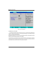
1
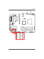
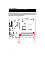
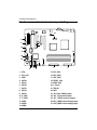
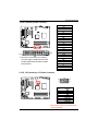
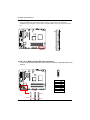
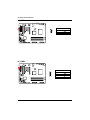
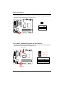
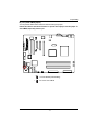
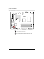
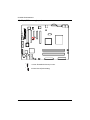
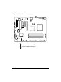
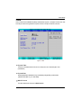
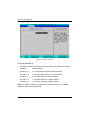
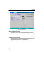
GA-5DXSL-RH Xeon® 3000 Series Processor Motherboard USER’S MANUAL Xeon® 3000 Series Processor Motherboard Rev. 1001 * The WEEE marking on the product indicates this product must not be disposed of with user's other household waste and must be handed over to a designated collection point for the recycling of waste electrical and electronic equipment!! * The WEEE marking applies only in European Union's member states. English GA-5DXSL-RH Motherboard Table of Content WARNING! ............................................................................................... 3 Chapter 1 GA-5DXSL-RH Motherboard Component ............................. 4 Chapter 2 Hardware Installation Process ............................................... 6 2-1: Install Memory Module ......................................................................... 6 2-2: Connect ribbon cables, cabinet wires, and power supply .................. 8 2-2-1 : I/O Back Panel Introduction .................................................................................. 8 2-3: Connectors Introduction & Jumper Setting........................................ 10 Chapter 3 BIOS Setup .......................................................................... 23 Main ........................................................................................................... 25 Advanced ................................................................................................... 27 Advanced Processor Options ........................................................................................ 28 Memory Configuration ..................................................................................................... 31 Advanced Chipset Control ............................................................................................. 32 PCI Configuration ............................................................................................................. 34 I/O Device Configuration ................................................................................................. 35 IDE Configuration ............................................................................................................. 40 Floppy Configuration ....................................................................................................... 42 Boot Configuration ............................................................................................................ 43 DMI Event Logging .......................................................................................................... 45 Hardware Monitor ............................................................................................................ 47 Security ...................................................................................................... 50 Server ......................................................................................................... 52 System Management ...................................................................................................... 53 Console Redirection ........................................................................................................ 54 Boot ............................................................................................................ 56 Exit ............................................................................................................. 57 Chapter 4 INTEL RAID BIOS Configuration ........................................... 62 2 Introduction WARNING! Computer motherboards and expansion cards contain very delicate Integrated Circuit (IC) chips. To protect them against damage from static electricity, you should follow some precautions whenever you work on your computer. 1. 2. Unplug your computer when working on the inside. Use a grounded wrist strap before handling computer components. If you do not have one, touch both of your hands to a safely grounded object or to a metal object, such as the power supply case. 3. Hold components by the edges and try not touch the IC chips, leads or connectors, or other components. 4. Place components on a grounded antistatic pad or on the bag that came with the components whenever the components are separated from the system. 5. Ensure that the ATX power supply is switched off before you plug in or remove the ATX power connector on the motherboard. Installing the motherboard to the chassis… If the motherboard has mounting holes, but they don’t line up with the holes on the base and there are no slots to attach the spacers, do not become alarmed you can still attach the spacers to the mounting holes. Just cut the bottom portion of the spacers (the spacer may be a little hard to cut off, so be careful of your hands). In this way you can still attach the motherboard to the base without worrying about short circuits. Sometimes you may need to use the plastic springs to isolate the screw from the motherboard PCB surface, because the circuit wire may be near by the hole. Be careful, don’t let the screw contact any printed circuit write or parts on the PCB that are near the fixing hole, otherwise it may damage the board or cause board malfunctioning. 3 English GA-5DXSL-RH Motherboard Chapter 1 GA-5DXSL-RH Motherboard Component No. 1 2 3 4 5 6 7 8 9 10 11 12 13 14 15 16 17 18 19 20 21 22 23 24 25 Descriprion CPU Intel 3200 chipset Intel ICH9R ITE IT8718F-S BIOS Flash ROM XGI Volari Z9s VGA Memory Broadcom BCM5721 GbE Intersil 6326 (PWM cintroller) Floppy cable connector Front USB 1 cable connector Front USB 2 cable connector COM2 SATA cable connector 0 SATA cable connector 1 SATA cable connector 2 SATA cable connector 3 SATA cable connector 4 SATA cable connector 5 Front Panel TPM connector IPMB2 IPMB1 IPMI BMC Mudole Slot PCI5 No. 26 27 28 29 30 31 32 33 34 35 36 37 38 39 40 41 42 43 44 45 46 47 48 49 4 Descriprion PCI4 PCI-E3 (x1 bandwidth) PCI-E2 (x4 bandwidth) PCI-E1 (x8 bandwidth) DIMMA1 DIMMA2 DIMMB1 DIMMB2 CPU fan cable connector Power fan cable connector System fan cable connector Front fan cable connector Rear fan cable connector I2C connector PS/2port USB port COM port VGA port LAN port 24-pin ATX power connector 8-pin ATX power connector Case open intrusion jumper Clear CMOS jumper Battery Introduction 43 24 22 6 25 27 26 44 8 7 28 41 40 38 29 46 23 48 42 12 1 2 11 13 4 20 21 5 48 49 9 30 3 34 31 32 39 37 18 45 36 16 14 19 17 15 5 33 35 10 English GA-5DXSL-RH Motherboard Chapter 2 Hardware Installation Process 2-1: Install Memory Module GA-5DXSL-RH has 4 dual inline memory module (DIMM) sokcets. It supports Dual Channels Technology. The BIOS will automatically detects memory type and size during system boot. For detail DIMM installation, please refer to the following instructions. Channel A Channel B 6 Hardware Installation Process Table 1. Supported DIMM Module Type Size 256MB 512MB 1GB Organization 8MB x 8 x 4 bks 16MB x 4 x 4bks 16MB x 8 x 4bks 32MB x 4 x 4bks 32MB x 8 x 4bks 64MB x 4 x 4bks RAM Chips/DIMM 8 16 8 16 8 16 Installation Steps: 1. Unlock a DIMM socket by pressing the retaining clips outwards. 2. Aling a DIMM on the socket such that the notch on the DIMM exactly match the notch in the socket. 3. Firmly insert the DIMMinto the socket until the retaining clips snap back in place. 4. When installing the memory into the DIMM socket, we recommend to populate the memory as a pair. One in Channel A module and one in Channel B module for best performance. Please populate DIMM starting from Channel A (Yellow slot). Note that each logical DIMM must be made of two identical DIMMs having the same device size on each and the same DIMM size. 5. Reverse the installation steps if you want to remove the DIMM module. 7 English GA-5DXSL-RH Motherboard 2-2: Connect ribbon cables, cabinet wires, and power supply 2-2-1 : I/O Back Panel Introduction X Y [ Z 8 \ Hardware Installation Process X PS/2 Keyboard and PS/2 Mouse Connector To install a PS/2 port keyboard and mouse, plug the mouse to the upper port (green) and the keyboard to the lower port (purple). Y USB Ports Before you connect your device(s) into USB connector(s), please make sure your device(s) such as USB keyboard, mouse, scanner, zip, speaker...etc. have a standard USB interface. Also make sure your OS supports USB controller. If your OS does not support USB controller, please contact OS vendor for possible patch or driver updated. For more information please contact your OS or device(s) vendors. Z Serial Port Modem can be connected to Serial port. [ VGA Port Monitor can be connected to VGA port. \ LAN Port The LAN port provides Internet connection of Gigabit Ethernet with data transfer speeds of 10/100/1000Mbps. This port supports IPMI 2.0. LAN LED Description LED2 (Green/Yellow) LED1 (Green) Name Color Condition Description LED1 Green Green ON BLINK LAN Link / no Access LAN Access - OFF OFF Idle 10Mbps connection Green OFF ON Port identification with 10 Mbps connection 100Mbps connection Green Yellow BLINK ON Port identification with 100Mbps connection 1Gbps connection Yellow BLINK Port identification with 1Gbps connection LED2 9 English GA-5DXSL-RH Motherboard 2-3: Connectors Introduction & Jumper Setting 19 2 14 13 25 11 27 10 26 12 21 15 24 20 18 23 4 17 22 9 8 76 16 1 5 1. ATX1 2. ATX_12V1 3. FDD1 4. SATA 0 5. SATA 1 6. SATA 2 7. SATA 3 8. SATA 4 9. SATA 5 10. F_USB1 11. F_USB2 12. COM2 13. IPMB1 14. IPMB2 3 15. CPU_FAN 16. PSU_FAN1 17. SYS_FAN1 18. FRONT_FAN 19. REAR_FAN 20. F_Panel1 21. TPM_20 22. BAT1 23. JP1 (Clear CMOS jumper) 24. JP2_1 (Password jumper) 25. JP3_1 (BIOS recovery jumper) 26. JP4_1 (BOOT select strapsj jumper) 27. JP4_2 (BOOT select strapsj jumper) 10 Connector Introduction 1) ATX1 (Auxukiary Power Connector) 1 13 12 24 ¾ AC power cord should only be connected to your power supply unit after ATX power cable and other related devices are firmly connected to the mainboard. PIN No. Definition 1 2 +3.3V +3.3V 3 4 GND +5V 5 6 GND +5V 7 8 GND POK 9 10 5VSB +12V 11 12 +12V +3.3V 13 14 +3.3V -12V 15 16 GND PSON 17 18 GND GND 19 20 GND -5V 21 22 +5V +5V 23 24 +5V GND 2 ) ATX_12V1 (Auxukiary +12V Power Connector) 5 8 1 4 Pin No. 1 2 3 4 5 6 7 8 Definition GND GND GND GND P12V_CPU P12V_CPU P12V_CPU P12V_CPU ¾This connector (ATX +12V) is used only for CPU Core Voltage. 11 English GA-5DXSL-RH Motherboard 3 ) FDD1 (Floppy cable connector) Please connect the floppy drive ribbon cables to FDD. It supports 720K,1.2M,1.44M and 2.88Mbytes floppy disk types. The red stripe of the ribbon cable must be the same side with the Pin1. 33 34 1 2 4/ 5/ 6/ 7/ 8/ 9 ) SATA 0~5 (Serial ATA cable connectors) You can connect the Serial ATA device to this connector, it provides you high speed transfer rates (3.0Gb/s). 1 7 Pin No. 1 2 3 4 5 6 7 SATA2 SATA0 SATA4 SATA5 SATA3 SATA1 12 Definition GND TXP TXN GND RXN RXP GND Connector Introduction 10/11 ) F_USB1/F-USB2 (Front USB cable connectors) Be careful with the polarity of the front USB connector. Check the pin assignment carefully while you connect the front USB cable, incorrect connection between the cable and connector will make the device unable to work or even damage it. For optional front USB cable, please contact your local dealer. F_USB2 Pin No. Definition 1 2 Power Power 1 2 3 4 USB DxUSB Dy- 9 10 5 6 USB Dx+ USB Dy+ 7 8 GND GND 9 10 No Pin NC F_USB1 12 ) COM2 (Serial port connector) 1 2 9 10 Pin No. 1 2 3 4 5 6 7 8 9 10 13 Definition DCDSIN2 SOUT2 DTR2GND DSR2RTS2CTS2RI2NC English GA-5DXSL-RH Motherboard 13 ) IPMB1 1 Pin No. 1 2 3 Definition Clock GND Data Pin No. 1 2 3 4 Definition Data GND Clock NC 14 ) IPMB2 1 14 Connector Introduction 15 ) CPU_FAN (CPU fan cable connector) Please note, a proper installation of the CPU cooler is essential to prevent the CPU from running under abnormal condition or damaged by overheating.The CPU fan connector supports Max. current up to 1A . 1 Pin No. 1 2 3 4 Definition GND 12V Sense Control 16 ) PSU_FAN1 (Power fan cable connector) This connector allows you to link with the cooling fan on the system case to lower the system temperature. 1 Pin No. 1 2 3 15 Definition GND +12V Sense English GA-5DXSL-RH Motherboard 17 ) SYS_FAN1 (System fan cable onnector) This connector allows you to link with the cooling fan on the system case to lower the system temperature. These connectors are for system use only. Pin No. 1 2 3 Definition GND +12V Sense 18/ 19 ) FRONT_FAN/REAR_FAN (System fan cable onnector) This connector allows you to link with the cooling fan on the system case to lower the system temperature. These connectors are for system use only. REAR_FAN 1 FRONT_FAN 1 Pin No. 1 2 3 4 FRONT_FAN 16 REAR_FAN Definition GND 12V Sense Control Connector Introduction 20 ) F_Panel (2X12 Pins Front Panel connector) Please connect the power LED, PC speaker, reset switch and power switch of your chassis front panel to the F_PANEL connector according to the pin assignment above. 1 2 12 24 Pin No. 1. 2. 3. 4. 5. 6. 7. 8. 9. 10. 11. 12. 13. 14. 15. 16. 17. 18. 19. 20. 21. 22. 23. 24. Signal Name PWLED+ 5VSB KEY COOL FAULT_LED+ PWLEDCOOL FAULT_LEDHD+ SYS_FAULT+ HDSYS_FAULTPWB+ L1_ACT PWB+_GND L1_LNKRST_BTNSENSOR_SDA RST_BTN_GND SENSOR_SCL ACPI SLEEP CASE_OPENACPI SLEEPL2_ACT NMI_SWL2_LNK- Description Power LED Signal anode (+) P5V Stand By Power Pin Removed Cooling fault LED Signal anode (+) Power LED Signal cathode(-) Cooling fault LED Signal cathode(-) Hard Disk LED Signal anode (+) System Fan Fail LED Signal Hard Disk LED Signal cathode(-) System Status LED Signal Power Button Signal anode (+) LAN1 access LED Signal Power Button Ground LAN1 linked LED Signal cathode(-) Reset Button cathode(-) SMBus Data Reset Button Ground SMBus Clock No Connect Chassis intrusion Signal No Connect LAN2 access LED Signal NMI Switch cathode(-) LAN2 linked LED Signal cathode(-) 17 English GA-5DXSL-RH Motherboard 21 ) TPM_20 (TPM cable connector) TPM, Trusted Platform Module offers facilities for secure generation of cryptographic keys, the ability to limit the use of keys (to either signing / verification or encryption / decryption). TPM chip is unique to a particular device, it is capable of performing platform authentication. 22 ) BAT1 (Battery) CAUTION Danger of explosion if battery is incorrectly replaced. Replace only with the same or equivalent type recommended by the manufacturer. Dispose of used batteries according to the manufacturer’s instructions. If you want to erase CMOS... 1.Turn OFF the computer and unplug the power cord. 2.Remove the battery, wait for 30 second. 3.Re-install the battery. 4.Plug the power cord and turn ON the computer. 18 Jumper Setting 23 ) JP1 (Clear CMOS jumper) You may clear the CMOS data to restore its default values by this jumper. Default value doesn’t include the “Shunter” to prevent from improper use this jumper. To clear CMOS, temporarily short 2-3 pin. 1 1-2 Close: Normal (Default setting) 1 2-3 Close: Clear CMOS 19 English GA-5DXSL-RH Motherboard 24 ) JP2_1 (Skip password jumper) 1 1 1-2 Close: Normal (Default setting) 2-3 Close: Skip Supervisor Password in BIOS setup menu 20 English GA-5DXSL-RH Motherboard 25 ) JP3_1 ( BIOS recovery jumper) 1 1 1-2 Close: Enable BIOS Recovery function. 2-3 Close: Normal (Default setting) 21 English GA-5DXSL-RH Motherboard 26/27 ) JP4_1/JP4_2 (Boot select straps jumper) JP4_2 JP4_1 1 1 1-2 Close: Normal (Default setting) 2-3 Close: Enable Boot select straps. 22 BIOS Setup Chapter 3 BIOS Setup BIOS Setup is an overview of the BIOS Setup Program. The program that allows users to modify the basic system configuration. This type of information is stored in battery-backed CMOS RAM so that it retains the Setup information when the power is turned off. ENTERINGSETUP Power ON the computer and press <F2> immediately will allow you to enter Setup. CONTROLKEYS <Ç> Move to previous item <È> Move to next item <Å> Move to the item in the left hand <Æ> Move to the item in the right hand <Esc> Main Menu - Quit and not save changes into CMOS Status Page Setup Menu and Option Page Setup Menu - Exit current page and return to Main Menu <+/PgUp> Increase the numeric value or make changes <-/PgDn> Decrease the numeric value or make changes <F1> General help, only for Status Page Setup Menu and Option Page Setup Menu <F2> Reserved <F3> Reserved <F4> Reserved <F6> Reserved <F7> Reserved <F8> Reserved <F9> Load the Optimized Defaults <F10> Save all the CMOS changes, only for Main Menu 23 GA-5DXSL-RH Motherboard GETTINGHELP Main Menu The on-line description of the highlighted setup function is displayed at the bottom of the screen. Status Page Setup Menu / Option Page Setup Menu Press F1 to pop up a small help window that describes the appropriate keys to use and the possible selections for the highlighted item. To exit the Help Window press <Esc>. z Main This setup page includes all the items in standard compatible BIOS. z Advanced This setup page includes all the items of AMI special enhanced features. (ex: Auto detect fan and temperature status, automatically configure hard disk parameters.) z Security Change, set, or disable password. It allows you to limit access the system and setup. z Server Server additional features enabled/disabled setup menus. z Boot This setup page include all the items of first boot function features. z Exit There are five optionsin this selection: Exit Saving Changes, Exit Discarding Changes, Load Optimal Defaults, Load Failsafe Defaults, and Discard Changes. 24 BIOS Setup Main Once you enter Phoenix BIOS Setup Utility, the Main Menu (Figure 1) will appear on the screen. Use arrow keys to select among the items and press <Enter> to accept or enter the sub-menu. Figure 1: Main System Time The time is calculated based on the 24-hour military time clock. Set the System Time (HH:MM:SS) System Date Set the System Date. Note that the “Day” automatically changed after you set the date. (Weekend: DD: MM: YY) (YY: 1099~2099) BIOS Version This item displays the information of BIOS Version. 25 GA-5DXSL-RH Motherboard BIOS Date This item identifies the BIOS refersh date. Processor Information These following items display all information of current CPU Type, CPU Speed, and CPU Count. These items are display-only which is determined by POST (Power On Self Test) of the BIOS. Total Memory Size This item identifies the total memory size. 26 BIOS Setup Advanced About This Section: Advanced With this section, allowing user to configure your system for basic operation. User can change the processor options, chipset configuration, PCI configuration and chipset control. Figure 2: Advanced 27 GA-5DXSL-RH Motherboard Advanced Processor Options Figure 2-1: Advanced Processor Options Advanced Processor Option This category includes the information of CPU Type, CPU Speed, Processor 1 CPUID, and Processor 1 L2 Cache. Setup menu for Thermal Management 2, C1 Enhanced Mode, C1 Enhanced Mode, Intel(R) Virtualization Technology, No Execute Mode Memory Protection, PECI Interface, and Intel EIST Support. Thermal Management2 Thermal Management 2 enhances the features of power reduction capability. When TM2 is enabled, it will reduce the frequency and VID which results in a saving of power consumption of processor. Enabled Enabled Thermal Management 2. (Default setting) Disabled Disables this function. 28 BIOS Setup C1 Enhanced Mode With enabling C1 Enhanced Mode, all loical processors in the physical processor have entered the C1 state, the processor will reduce the core clock frequency to system bus ratio and VID. Enabled Enabled C1 Enhanced Mode. Disabled Disables C1 Enhanced Mode. (Default setting) Intel (R) Virtualization Technology Intel(R) Virtualization Technology will allow a platform to run multiple operating systems and applications in independent partitions. With virtualization, one computer system can function as multiple “virtual” systems. With processor and I/O enhancements to Intel’s various platforms, Intel Virtualization Technology can improve the performance and robustness of today’s softwareonly virtual machine solutions. Enabled Enabled VT Feature. Disabled Disables VT Feature. (Default setting) No Execute Mode Mem. Protection Enabled Enable No Execute Mode Memory Protection function. (Default setting) Disabled Disables No Execute Mode Memory Protection function. PECI Interface The Platform Environmental Control Interface (PECI Interface) is designed specifically to convey system management information from the processor. It is a proprietary single wire bus between the processor and the chipset or other health monitoring device. Data from the Digital Thermal Sensors are processed and stored in a processor register (MSR) which is queried through the Platform Environment Control Interface (PECI). Enabled Enable PECI Interface Disabled Disable this function. (Default setting) 29 GA-5DXSL-RH Motherboard Intel EIST Support Select the Power Management desired: Enabled C states and GV1/GV3 are enabled. (Default setting) C States Only GV1/GV3 are disabled. GV1/GV3 Only C states are disabled. Disabled C states and GV1/GV3 are disabled. 30 BIOS Setup Memory Configuration Figure 2-2: Memory Configuration System Memory/Extended Memory/DIMM Group A1,A2, B1, B2 Status These category is display-only which is determined by POST (Power On Self Test) of the BIOS. Memory Reset Yes Select ‘Yes’, system will clear the memory error status. Save the changes and restart system. After rebooting system, the Memory Reset item will set to ‘No’ automatically. No Disable this function. (Default setting) 31 GA-5DXSL-RH Motherboard Advanced Chipset Control Figure 2-3: Advanced Chipset Control Wake On LAN / PME This option allow user to determine the action of the system when a LAN/PME wake up event occurs. Enabled Enable Wake On LAN/PME. (Default setting) Disabled Disable this function. Note: This item must enabled if you’re running under Windows operating system. Wake On Ring This option allow user to determine the action of the system power is off and the modem is ringing. Enabled Enable Wake On Ring. Disabled Disable this function. (Default setting) Note: This item must enabled if you’re running under Windows operating system. 32 BIOS Setup Wake On RTC Alarm When "RTC Alarm Resume" item is set to enabled, system will wakeup from RTC. (This item will be functionalized under ACPI OS) Enabled Enable alarm function to POWER ON system. Disabled Disable this function. (Default setting) Note: This item must enabled if you’re running under Windows operating system. 33 GA-5DXSL-RH Motherboard PCI Configuration Figure 2-4: PCI Configuration PCI Slot 1/2/3/4 Option ROM Enabled Enableing this item to initialize device expansion ROM. (Defualt setting) Disabled Disable this function. LAN1 Option ROM Scan Enabled Enableing this item to initialize device expansion ROM. (Defualt setting) Disabled Disable this function. Onboard VGA Control Enabled Enable the onboad VGA device. (Defualt setting) Disabled Disable this function. 34 BIOS Setup I/O Device Configuration Figure 2-5: I/O Device Configuration Serial Port A This allows users to configure serial prot A by using this option. Enabled Enable the configuration (Default setting) Disabled Disable the configuration. Base I/O Address/IRQ 3F8 Set IO address to 3F8. (Default setting) 2F8 Set IO address to 2F8. 3E8 Set IO address to 3E8. 2E8 Set IO address to 2E8. 35 GA-5DXSL-RH Motherboard Serial Port B This allows users to configure serial prot B by using this option. Enabled Enable the configuration Disabled Disable the configuration.(Default setting) Base I/O Address/IRQ 3F8 Set IO address to 3F8. 2F8 Set IO address to 2F8. (Default setting) 3E8 Set IO address to 3E8. 2E8 Set IO address to 2E8. Parallel Port This allows users to configure parallel port by using this option. Enabled Enable the configuration. Disabled Disable the configuration. (Default setting) Mode This option allows user to set Parallel Port transfer mode. Bi-directional Use this setting to support bi-directional transfers on the parallel port. (Default setting) EPP Using Parallel port as Enhanced Parallel Port. ECP Using Parallel port as Extended Capabilities Port. Base I/O Address 378 Set IO address to 378 278 Set IO address to 278. 36 BIOS Setup Iterrupt IRQ5 Set Interrupt as IRQ5. (Default setting) IRQ7 Set Interrupt as IRQ7. (Default setting) PS/2 Mouse Set this option ‘Enabled’ to allow BIOS support for a PS/2 - type mouse. Enabled ‘Enabled’ forces the PS/2 mouse port to be enabled regardless if a mouse is present. (Default setting) Disabled ‘Disabled’ prevents any installed PS/2 mouse from functioning, but frees up IRQ12. USB Controller This item allows users to enable or disable the USB device by setting item to the desired value. Enabled Enable USB controller. (Default setting) Disabled Disbale this function. Legacy USB Support This option allows user to function support for legacy USB. Enabled Enables support for legacy USB (Default setting) Disabled Disables support for legacy USB. 37 GA-5DXSL-RH Motherboard Serial ATA Enabled Enables on-board serial ATA function. (Default setting) Disabled Disables on-board serial ATA function. ` Native Mode Operation This option allows user to set the native mode for Serial ATA function. Auto Auto detected. (Default setting) Serial ATA Set Native mode to Serial ATA. ` SATA RAID Enable Enabled Enabled SATA RAID function. Disabled Disable this function. (Default setting) 38 BIOS Setup ` SATA AHCI Enable Enabled Set this item to enable SATA AHCI function for WinXP-SP1+IAA driver supports AHCI mode. Disabled Disabled this function. (Default setting) 39 GA-5DXSL-RH Motherboard IDE Configuration Figure 2-6: IDE Configuration SATA Port 1/2/3/4/5/6 The category identifies the types of hard disk from drive 1 to 6 that has been installed in the computer. There are two types: auto type, and manual type. Manual type is user-definable; Auto type which will automatically detect HDD type. Note that the specifications of your drive must match with the drive table. The hard disk will not work properly if you enter improper information for this category. If you select User Type, related information will be asked to enter to the following items. Enter the information directly from the keyboard and press <Enter>. Such information should be provided in the documentation form your hard disk vendor or the system manufacturer. 40 BIOS Setup TYPE 1-39: Predefined types. Users: Set parameters by User. Auto: Set parameters automatically. (Default Vaules) CD-ROM: Use for ATAPI CD-ROM drives or double click [Auto] to set all HDD parameters automatically. ATAPI Removable: Removable disk drive is installed here. Multi-Sector Transfer This field displays the information of Multi-Sector Transfer Mode. Disabled: The data transfer from and to the device occurs one sector at a time. Auto: The data transfer from and to the device occurs multiple sectors at a time if the device supports it. LBA Mode This field shows if the device type in the specific IDE channel support LBA Mode. 32-Bit I/O Enable this function to max imize the IDE data transfer rate. Transfer Mode This field shows the information of Teansfer Mode. Ultra DMA Mode This filed displays the DMA mode of the device in the specific IDE channel. 41 GA-5DXSL-RH Motherboard Floppy Configuration Figure 2-7: Floppy Configuration Legacy Diskette A This category identifies the type of floppy disk drive A that has been installed in the computer. Disabled Disable this device. 360KB, 5 in. 31/2 inch AT-type high-density drive; 360K byte capacity 1.2MB, 31/2 in. 31/2 inch AT-type high-density drive; 1.2M byte capacity 720K, 31/2 in. 31/2 inch double-sided drive; 720K byte capacity 1.44M, 31/2 in. 31/2 inch double-sided drive; 1.44M byte capacity. 2.88M, 31/2 in. 31/2 inch double-sided drive; 2.88M byte capacity. 1/4 Note: The 1.25MB,31/2 reference a 1024 byte/sector Japanese media format. The 1.25MB,31/2 diskette requires 3-Mode floppy-disk drive. 42 BIOS Setup Boot Configuration Figure 2-8: Boot Configuration Boot time Diagnostic Screen When this item is enabled, system will shows Diagnostic status when system boot. Enabled Display the diagnostic screen during system boot. Disabled Disable this function. (Default setting) Multiprocessor Specification This option allows user to configure the multiprocessor(MP) specification revision level. Some operating system will require 1.1 for compatibility reasons. 1.4 Support MPS Version 1.4 . (Default setting) 43 GA-5DXSL-RH Motherboard 1.1 Support M PS Version 1.1. Post Error Pause If this item is set to enabled, the system will wai for user intervention on critical POST errors. If this item is disabled, the system will boot with no intervention if possible. Enabled Enable Post Error Pause. (Default setting) Disabled Disable this function. AC-LINK This option provides user to set the mode of operation if an AC / power loss occurs. Power On System power state when AC cord is re-plugged. Stay Off Do not power on system when AC power is back. Last State Set system to the last sate when AC power is removed. Do not power on system when AC power is back. (Default setting) NumLock This option allows user to select power-on state for NumLock. On Enable NumLock. (Default setting) Off Disable this function. Security Mode for PWR/RST button Enabled Enable security mode for power and reset buttons. Disabled Disable this function. (Default setting) 44 BIOS Setup DMI Event Logging Figure 2-9: DMI Event Logging Event log vaildity/Event log capacity These two items display the current status of Event log vaildity and Event log capacity. View DMI event log Press [Enter] to view DMI event log. Event Logging Enabled Select Enabled to allow logging of DMI events. (Default setting) Disabled Disable this function. 45 GA-5DXSL-RH Motherboard Mark DMI as read Press [Enter] to mark all DMI events in the event log as read. Clear all Event Logs Yes Clear all event logs. No Disable this function. (Default setting) 46 BIOS Setup Hardware Monitor Figure 2-10: Hardware Monitor 47 GA-5DXSL-RH Motherboard Figure 2-10-1: Voltage Monitor Figure 2-10-2: Fan Monitor 48 BIOS Setup CPU / SystemTemperature Display the current CPU temperature and system temperature. Voltage Monitor: DDR1V8, VCC3, VCORE, 12V2, 5V Detect system's voltage status automatically. FAN Monitor: REAR FAN/ FRONT FAN/ CPU FAN Display the current front fanspeed, rear fan speed, and CPU fan speed. 49 GA-5DXSL-RH Motherboard Security * About This Section: Security In this section, user can set either supervisor or user passwords, or both for different level of password securities. In addition, user also can set the virus protection for boot sector. Figure 3: Security Set Supervisor Password You can install and change this options for the setup menus. Type the password up to 6 characters in lengh and press <Enter>. The password typed now will clear any previously entered password from the CMOS memory. You will be asked to confirm the entered password. Type the password again and press <Enter>. You may also press <Esc> to abort the selection and not enter a specified password or press <Enter> key to disable this option. 50 BIOS Setup Set User Password You can only enter but do not have the right to change the options of the setup menus. When you select this function, the following message will appear at the center of the screen to assist you in creating a password. Type the password up to 6 characters in lengh and press <Enter>. The password typed now will clear any previously entered password from the CMOS memory. You will be asked to confirm the entered password. Type the password again and press <Enter>. You may also press <Esc> to abort the selection and not enter a specified password. Password on boot Password entering will be required when system on boot. Enabled Requries entering password when system on boot. Disabled Disable this function. (Default setting) 51 GA-5DXSL-RH Motherboard Server Figure 4: Server 52 GA-5DXSL-RH Motherboard System Management Figure 4-1: System Management Server Management This category allows user to view the server management features. Including information of BIOS Version, Product Name, System Version, System Serial Number, Main Board ID, Main Board Serial Number, and, LAN1/2 MAC Address . All items in this menu cannot be modified, display only. Clear Case Open Status Press [Enter] to clear the Case Open Status. 53 BIOS Setup Console Redirection Figure 4-2: Console Redirection BIOS Redirection Port If this option is set to enabled, it will use a port on the motherboard. Serial Port A Use Serial Port A as he COM port address. Serial Port B Use Serial Port B as he COM port address. Disabled Disable this function. (Default setting) Baud Rate This option allows user to set the specified baud rate. Options 300, 1200, 2400, 9600, 19.2K, 38.4K, 57.6K, 115.2K. Terminal Type This option allows user to select the specified terminal type. This is defined by IEEE. Options VT100, VT100 8bit, PC-ANSI 7bit, VT100+, VT-UTF8 54 GA-5DXSL-RH Motherboard Flow Control This option provide user to enable the flow control function. None Not supported. XON/OFF Software control. CTS/RTS Hardware control. (Default setting) Continue C.R. after POST This option allows user to enable console redirection after O.S has loaded. On Enable console redirection after O.S has loaded. Off Disable this function. (Default setting) 55 BIOS Setup Boot Figure 5: Boot Boot Priority Order This field determines which type of device the system attempt to boot from after PhoenixBIOS Post completed. Specifies the boot sequence from the available devices. If the first device is not a bootable device, the system will seek for next available device. Key used to view ot configure devices: Up and Down arrows select a device. <+> and <-> moves the device up or down. <f> and <r> specifies the device fixed or removable. <x> exclude or include the device to boot. <1-4> Loads default boot secquence. 56 GA-5DXSL-RH Motherboard Exit Figure 6: Exit * About This Section: Exit Once you have changed all of the set values in the BIOS setup, you should save your changes and exit BIOS setup program. Select “Exit” from the menu bar, to display the following sub-menu. Exit Saving Changes Exit Discarding Changes Load Settup Default Discard Change Save Changes 57 BIOS Setup Exit Saving Changes This option allows user to exit system setup with saving the changes. Press <Enter> on this item to ask for the following confirmation message: Pressing ‘Y’ to store all the present setting values tha user made in this time into CMOS. Therefore, whenyou boot up your computer next time, the BIOS will re-configure your system according data in CMOS. 58 GA-5DXSL-RH Motherboard Exit Discarding Changes This option allows user to exit system setup without changing any previous settings values in CMOS. The previous selection remain in effect. This will exit the Setup Utility and restart your compuetr when selecting this option. Load Settup Default This option allows user to load default values for all setup items. When you press <Enter> on this item, you will get a confirmation dialog box with a message as below: 59 BIOS Setup Discard Changes This option allows user to load previos values from CMOS for all setup item. When you press <Enter> on this item, you will get a confirmation dialog box with a message as below: 60 GA-5DXSL-RH Motherboard Save Changes This option allows user to save setup dat ato CMOS. When you press <Enter> on this item, you will get a confirmation dialog box with a message as below: Press [Yes] to save setup daya to CMOS. 61 INTEL RAID BIOS Configuration Chapter 4 INTEL RAID BIOS Configuration Configuring the Intel RAID BIOS The Intel RAID BIOS setup lets you choose the RAID array type and which hard drives you want to make part of the array. Entering the RAID BIOS Setup 1. After rebooting your computer, wait until you see the RAID software prompting you to press Ctrl + I. The RAID prompt appears as part of the system POST and boot process prior to loading the OS. You have a few seconds to press Ctrl + I before the window disappears. Intel(R) Matrix Storage Manager option ROM V5.0.0.1011 ICH7R wRAID5 Copyright(C) 2003-04 Intel Corporation. All Rights Reversed. RAID Volumes : None Defined. Physical Disks : Port Driver Model 0 ST3120026AS 1 ST3120026AS Serial # 3JT354CP 3JT329JX Size Type/Status(Vol ID) 111.7GB Non-RAID Disk 111.7GB Non-RAID Disk Press <CTRL - I> to enter Configuration Utility Press Ctrl + I. The Intel RAID Utility - Create RAID Volume window appears (as illustrated below). Intel(R) Matrix Storage Manager option ROM V5.0.0.1011 ICH7R wRAID5 Copyright(C) 2003-04 Intel Corporation. All Rights Reversed. [ MAIN MENU ] 1. Create RAID Volume 2. Delete RAID Volume 3. Reset Disks to Non-RAID 4. Exit [ DISK/VOLUME INFORMATION ] RAID Volumes : None Defined. Physical Disks : Port Driver Model 0 ST3120026AS 1 ST3120026AS [KL]-Select Serial # 3JT329JX 3JT354CP Size Type/Status(Vol ID) 111.7GB Non-RAID Disk 111.7GB Non-RAID Disk [ESC]-Exit 62 [ENTER]-Select Menu GA-5DXSL-RH Motherboard Create RAID Volume Press Enter under Create RAID Volume to set up RAID. Intel(R) Matrix Storage Manager option ROM V5.0.0.1011 ICH7R wRAID5 Copyright(C) 2003-04 Intel Corporation. All Rights Reversed. [ CREATE VOLUME MENU ] Name : RAID_Volume0 RAID Level : RAID0(Stripe) Disks : Select Disks Strip Size : 128KB Capacity : 223.5 GB Create Volume [ HELP ] Enter a string between 1 and 16 characters in length that can be used to uniquely identify the RAID volume. This name is case sensitive and can not contain special characters. [KL]-Change [TAB]-Next [ESC]-Previous Menu [ENTER]-Select After entering the Create Volume Menu, you can set disk name with 1~16 letters (letters cannot be special characters) under Name item. After setting disk name, press Enter to select RAID Level. Intel(R) Matrix Storage Manager option ROM V5.0.0.1011 ICH7R wRAID5 Copyright(C) 2003-04 Intel Corporation. All Rights Reversed. [ CREATE VOLUME MENU ] Name : RAID_Volume0 RAID Level : RAID0(Stripe) Disks : Select Disks Strip Size : 128KB Capacity : 223.5 GB Create Volume [ HELP ] Choose the RAID level best suited to your usage model. RAID0- Data striped across multiple physical drives for performance. RAID1- Data mirrored across multiple physical drives for redundancy. RAID0+1- Striped volume whose segments are RAID 1 volumes. Requires four hard drives. Functionally equivalent to RAID 0+1. RAID5- Data and parity striped across three or more physical drives for performance and redundancy. [KL]-Change [TAB]-Next [ESC]-Previous Menu [ENTER]-Select There are four RAID levels: RAID0(Stripe), RAID1(Mirror), RAID 0+1 (Striping + Mirroring) and RAID5. After selecting the RAID level, press Enter to select Strip Size. 63 INTEL RAID BIOS Configuration The KB is a unit of Strip Size. You can set disk block size with this item. The disk block size can be set from 4KB to 128KB. After you set disk block size, press Enter to set disk Capacity. Intel(R) Matrix Storage Manager option ROM V5.0.0.1011 ICH7R wRAID5 Copyright(C) 2003-04 Intel Corporation. All Rights Reversed. [ CREATE VOLUME MENU ] Name : RAID_Volume0 RAID Level : RAID0(Stripe) Disks : Select Disks Strip Size : 128KB Capacity : 223.5 GB Create Volume [ HELP ] The following are typical values: RAID 0 - 128KB RAID 1 - 64KB RAID 5 - 64KB [KL]-Change [TAB]-Next [ESC]-Previous Menu [ENTER]-Select Intel(R) Matrix Storage Manager option ROM V5.0.0.1011 ICH7R wRAID5 Copyright(C) 2003-04 Intel Corporation. All Rights Reversed. [ CREATE VOLUME MENU ] Name : RAID_Volume0 RAID Level : RAID0(Stripe) Disks : Select Disks Strip Size : 128KB Capacity : 223.5 GB Create Volume [ HELP ] Enter the volume capacity. The default value indicates the maximum volume capacity using the selected disks. If less than the maximum capacity is chosen, creation of a second volume is needed to utilize the remaining space. [KL]-Change [TAB]-Next [ESC]-Previous Menu Press Enter to enter Create Volume after setting disk capacity. 64 [ENTER]-Select GA-5DXSL-RH Motherboard Press Enter under the Create Volume item. Intel(R) Matrix Storage Manager option ROM V5.0.0.1011 ICH7R wRAID5 Copyright(C) 2003-04 Intel Corporation. All Rights Reversed. [ CREATE VOLUME MENU ] Name : RAID_Volume0 RAID Level : RAID0(Stripe) Disks : Select Disks Strip Size : 128KB Capacity : 223.5 GB Create Volume [ HELP ] Press "ENTER" to Create the specified volume [KL]-Change [TAB]-Next [ESC]-Previous Menu [ENTER]-Select An alert bar will be displayed warning you that all data on selected disks will be lost. Please press Y to complete the set-up of RAID. Intel(R) Matrix Storage Manager option ROM V5.0.0.1011 ICH7R wRAID5 Copyright(C) 2003-04 Intel Corporation. All Rights Reversed. [ CREATE VOLUME MENU ] Name : RAID_Volume0 RAID Level : RAID0(Stripe) Disks : Select Disks Strip Size : 128KB Capacity : 223.5 GB Create Volume WARNING : ALL DATA ON [SELECTED DISKS WILL BE LOST. HELP ] Are you sure you want to creat this volume? (Y/N) : Press "ENTER" to Create the specified volume [KL]-Change [TAB]-Next [ESC]-Previous Menu 65 [ENTER]-Select INTEL RAID BIOS Configuration After the completion, you will see the detailed information about the RAID, such as RAID level, disk block size, disk name and disk capacity, etc. Intel(R) Matrix Storage Manager option ROM V5.0.0.1011 ICH7R wRAID5 Copyright(C) 2003-04 Intel Corporation. All Rights Reversed. [ MAIN MENU ] 1. Create RAID Volume 2. Delete RAID Volume 3. Reset Disks to Non-RAID 4. Exit [ DISK/VOLUME INFORMATION ] RAID Volumes : ID Name Bootable 0 RAID_Volume0 RAID(Stripe) Physical Disks : Port Driver Model 0 ST3120026AS 1 ST3120026AS Serial # 3JT329JX 3JT354CP Level [KL]-Select 128KB Strip Size Status 223.5GB Normal Yes Size 111.7GB 111.7GB Type/Status(Vol ID) Member Disk(0) Member Disk(0) [ESC]-Exit [ENTER]-Select Menu Delete RAID Volume If you want to delete a RAID volume, please select the Delete RAID Volume option. Press Enter key and follow the instructions on the screen. Intel(R) Matrix Storage Manager option ROM V5.0.0.1011 ICH7R wRAID5 Copyright(C) 2003-04 Intel Corporation. All Rights Reversed. [ MAIN MENU ] 1. Create RAID Volume 2. Delete RAID Volume 3. Reset Disks to Non-RAID 4. Exit [ DISK/VOLUME INFORMATION ] RAID Volumes : ID Name Bootable 0 RAID_Volume0 RAID(Stripe) Physical Disks : Port Driver Model 0 ST3120026AS 1 ST3120026AS Serial # 3JT329JX 3JT354CP [KL]-Select Level 128KB [ESC]-Exit 66 Strip Size Status 223.5GB Normal Yes Size 111.7GB 111.7GB Type/Status(Vol ID) Member Disk(0) Member Disk(0) [ENTER]-Select Menu