1
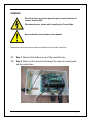
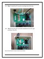
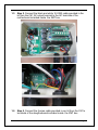
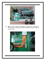
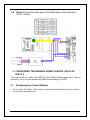
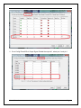
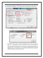
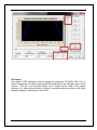
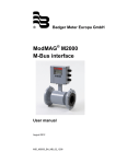
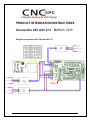
PRODUCT INTEGRATION INSTRUCTIONS
Connection C61 with C11 MARCH, 2015
Diagram connection of the C61 with the C11
User’s Manual
Page i
WARNING
Electrical shock or serious physical injury could result due to
misuse Control BOX.
Disconnect power cables while installing the Control Box.
Read and follow instructions on the manual.
Images below show the step required to install the kit into the XMT control box.
1.1
Step 1. Remove the bottom cover of the controller box.
1.2
Step 2. Remove all connections between the manual control panel
and the control box.
User’s Manual
Page 1
1.3
Step 3. Install the C61 over the mounting holes of the box.
1.4
Step 4. Insert the AC cord cable receptacles to the AC input
terminals of the C61.
Note: Connect to the C61 only the neutral and line terminal.`
User’s Manual
Page 2
1.5
Step 5. Connect the black and white 16 AWG cable provided in the
kit from the C61 AC output terminal to the AC terminals of the
motherboard incluided inside the XMT box.
1.6
Step 6. Connect the 5 wires cable provided in our kit from the C61 to
terminals of the daugtherboard incluided inside the XMT box.
User’s Manual
Page 3
1.7
Step 7. Insert an standar RJ45 cable through the slot of one side of
the control box, and plug the cable in the RJ45 connector located in
the C61 board.
User’s Manual
Page 4
1.8
Step 8.Connect the other side of the RJ45 cable to the terminal of
the C11 board.
2. CONFIGURING THE VARIABLE SPEED CONTROL (PIN 14 OF
THE C11)
This function lets you control your XMT KIT with PWM and REV signals, as if it was an
axis motor. The C11 board converts the PWM into an analog (0-10VDC).
2.1
Configuring the Control Software
1. Go to Config / Ports &Pins / Motor Outputs. Enable the spindle and select the port and pins
you wired for step and direction
User’s Manual
Page 5
2. Go to Config/ Ports &Pins/ Output Signal. Enable the output #1, select port 1 and pin 1
User’s Manual
Page 6
3. Go to Config / Ports&Pins / Spindle Setup. In the motor control box, check Use Spindle
Motor Output and Step /Dir Motor. Under Pulley Ratios set the pulley ratios of the machine.
4. Go to Config / Spindle Pulleys. Under Pulley Ratios set the pulley ratios of the machine
5. Go to Config / Motor Tuning / Spindle. On Steps per unit put 1,000, set velocity to
maximum. For Acceleration, choose the acceleration that you feel comfortable with.
Start slow, increase acceleration as you test your system. Under Step Pulse length, use
a number from 3 to 5, but start with 3. This number is directly proportional to the final
voltage you will get in the analog output. Use this number and the fine tuning pot to
adjust the voltage you want to get at max speed.
User’s Manual
Page 7
Disclaimer:
Use caution. CNC machines could be dangerous machines. DUNCAN USA, LLC or
Arturo Duncan are not liable for any accidents resulting from the improper use of these
devices. This Kit is not fail-safe device, and it should not be used in life support
systems or in other devices where its failure or possible erratic operation could cause
property damage, bodily injury or loss of life.
User’s Manual
Page 8