1
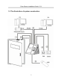
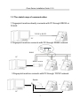
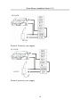
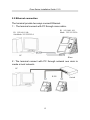
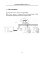
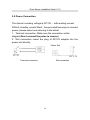
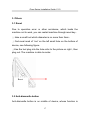
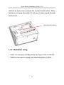
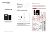
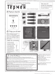
iFace Series Installation Guide Version:1.0 Date:Sep 2009 About this Guide This guide provides actual installation instructions only. For information regarding user instructions, please refer to “iFace Series User Manual”. iFace Series Installation Guide V1.0 Content 1 System Configuration.............................................................................. 1 1.1 View of operation panel................................................................ 1 1.2 The illustration of system construction .......................................... 2 1.3 The sketch map of communication................................................ 3 2 Installation.............................................................................................. 4 2.1 Door sensor connection ............................................................... 6 2.2 Exitbutton connection.................................................................. 6 2.3 Time Ring connection .................................................................. 7 2.4 Door lock connection.................................................................... 8 2.5 Ethernet connection ................................................................... 12 2.6 RS232 connection...................................................................... 13 2.7 RS485 connection...................................................................... 14 2.8 Wiegand Output Connection....................................................... 15 2.9 Power Connection...................................................................... 16 3. Others ................................................................................................. 17 3.1 Reset......................................................................................... 17 3.2 Antidismantle button.................................................................. 17 3.3 U flash disk using....................................................................... 18 3.4 Reserve Battery ......................................................................... 19 I iFace Series Installation Guide V1.0 1 System Configuration 1.1 View of operation panel LED light Touch screen Fingerprint Sensor Camera Baseline Battery slot Power TCP/IP USB Loudspeaker Power key Reset key USB 1 iFace Series Installation Guide V1.0 1.2 The illustration of system construction 2 iFace Series Installation Guide V1.0 1.3 The sketch map of communication 1 Fingerprint machine directly connects with PC through RS232 or TCP/IP. TCP/IP or RS232 PC 2 Fingerprint machine connects with PC through RS485 network. RS485 PC RS485 Switch … RS232 3 Fingerprint machine connects with PC through TCP/IP network. Switch TCP/IP … TCP/IP PC TCP/IP 3 iFace Series Installation Guide V1.0 2 Installation Caution: Do not to connect peripheral equipment before the power of the device is cut down, otherwise it is possible to damage the device badly. Please follow instruction to connect peripheral equipment。 ① Door sensor connection (Sensor, GND) ② Exitbutton connection ( Button ,GND) ③ Alarm connection ( NC2,COM2,NO2) ④ Door lock connection ( NC1,COM1,NO1) ⑤ Ethernet connection ( RJ451, RJ452, RJ453,RJ456) ⑥ RS232 connection ( 232T,232R,GND) ⑦ RS485 connection ( 485A,485B) ⑧ Wiegand output connection ( WD0,WD1,GND) ⑨ Power connection ( +12V,GND) Power TCP/IP USB 4 iFace Series Installation Guide V1.0 The definition of terminal connection : From left to right 1 NO2 Connect to Cable Bell NO terminal 2 COM 2 Connect to Cable Bell COM terminal Tie up together 3 NC2 Connect to Cable Bell NC terminal 4 Sens or Connect to Door sensor 5 GND For Door sensor and release button 6 Butto n Connect to Release button 7 NO1 Connect to Lock NC terminal 8 COM 1 Connect to Lock COM terminal 9 NC1 Connect to Lock NO terminal 10 485 Connect to RS485B 11 485+ Connect to RS485A 12 GND Connect to RS232 GND Tie up together Tie up together and Weigand 13 TXD Connect to RS232 TXD 14 RXD Connect to RS232 RXD 15 WD0 Connect to Weigand outWD0 16 WD1 Connect to Weigand outWD1 17 SGN D Connect to screen wire 18 GND Connect to Power GND 19 +12V Connect to Power +12v 5 Tie up together Tie up together Tie up together Tie up together iFace Series Installation Guide V1.0 2.1 Door sensor connection The door sensor is used to detect the door openclose state , terminal can monitor if the door has been unauthorized open through the door sensor, at this time it can output a alarm signal, moreover, terminal can trigger prompt warning if the door is not close tightly. 2.2 Exitbutton connection The exitbutton is installed for indoor operation. When the switch of the button is close, the door will open. The distance is approximately 1400mm from ground to exitbutton bottom. Make sure that the exitbutton position is to align correct, upright and the connection is accurate and reliable. (Unused exposed end of cable should be cut off, and use insulating tape to wrap it.)Pay attention to electromagnetic disturbance. (For example: The light switch, the computer and so on) Door Sensor Button Power Supply 6 iFace Series Installation Guide V1.0 2.3 Time Ring connection Connect the electrical bell to the fingerprint machine, when arrive the appoint time, the fingerprint machine will send signal to trigger relay。 The terminal supports both NormalOpen bells and NormalClose bells at the same time. ①NormalOpen bells iFace Bell Power supply ②NormalClose bells Bell iFace Power supply 7 iFace Series Installation Guide V1.0 2.4 Door lock connection The way of installing door lock depends on the type of lock and local condition. Internal resistor which comes from long distance transfer should be taken into consideration when selecting the cable of electric power. The door lock should be installed reliable and stable .Ensure the wiring is correct. For the strike lock and electromagnetic lock, you should pay attention to positive and negative terminal connection. The unused bare end of wire should be cut off and use insulating tape to wrap it. The delay time of strike lock is adjustable according to different conditions. Select electric lock :it is better to use strike lock for the two –direction opening glass door (both open to inside or outside direction ) ,for the single opening wood door in company internal , we recommend to use magnetic lock, the magnetic lock also be called as electric magnetic lock,. The magnetic lock is more reliable than the strike lock, but the strike lock is much safer than the magnetic lock. In the small living community, it is better to use strike lock and magnetic force lock. The electric control lock gives out higher noise; the electric control lock is commonly used to building communication. Now there is a soundless electric control lock which is able to be applied. Please pay attention, the lock is made of iron and easy rust, so you must beware of not exposing it to water or harsh condition, there are some other electric locks available, we don’t recommend you to use them. Connect with electric lock The NormalOpen lock is open when the power is on. The NormalClose lock is closed when power is on. The machine 8 iFace Series Installation Guide V1.0 supports both of the two kinds of locks at the same time. The way of lock connection changes with the type of lock. For NO lock, the NO terminal will be used; for NC lock, the NC terminal will be used. This access control machine is powered by DC12V and work current 400mA. If the lock work electric power is DC12V and the work current is less than 1000mA, the fingerprint machine and lock are able to be powered by one adapter together, please refer to table 1, 2. In the following three cases, we recommend that fingerprint machine and lock are powered separately. 1)The working voltage of the lock is DC12V, but the current difference of the fingerprint machine and the lock doesn’t exceed 1A. 2) The lock voltage is not DC12V. 3) The distance between lock and fingerprint machine is too far. 9 iFace Series Installation Guide V1.0 NO LOCK DC12V Picture1 Power by one supply NC LOCK DC12V Picture2 power by one supply 10 iFace Series Installation Guide V1.0 Lock Power DC12V NO LOCK Picture 3 The terminal and lock powered by independent adapters NC LOCK DC12V Lock Power Picture 4 The terminal and lock powered by independent adapters 11 iFace Series Installation Guide V1.0 2.5 Ethernet connection The terminal provide two ways connect Ethernet. 1) The terminal connect with PC through cross cable。 IP:192.168.1.101 Mask:255.255.255.0 IP:192.168.1.100 Sub Mask: 255.255.255.0 PC iFace 2)The terminal connect with PC through network and HUB to create a local network。 PC Switch 12 iFace Series Installation Guide V1.0 2.6 RS232 connection The terminal connect with PC through RS232 Note:Don’t upload or download facial module through RS232, because the large data will effect the transfer speed. iFace PC Serial Port 13 iFace Series Installation Guide V1.0 2.7 RS485 connection The terminal connect with PC through RS485 Note:Don’t upload or download facial module through RS485 because the large data will effect the transfer speed. RS485 RS485 Switch PC 机 … RS232 面部机 14 面部机 iFace Series Installation Guide V1.0 2.8 Wiegand Output Connection The device has Wiegand output function, can connect the majority access controllers on the market, at this time it is used as a reader Note: 1)The distance between device and access controller or card reader shouldn’t be over 90 meters (If a longer distance is needed or there is interference in using environment, please use Wiegand signal de lay.). 2) To ensure the stability of the Wiegand signal, the device must share the GND with controller or Weigand reader. 3) If the distance of Wiegand output or 485 communication is over 90 meters, in order to reduce the interference caused by the long distance, it is suggested to use the cable with shield and connect the shield cable to the SGND terminal. 15 iFace Series Installation Guide V1.0 2.9 Power Connection The device’s working voltage is DC12V,,with working current 500mA, standby current 50mA . has provided two ways to connect power, please select one referring to the actual. 1.Terminal connection, Make sure the connection as the diagram(Don’t connect the poles in reverse.). 2.Slot connection :Insert the plug of DC12V adapter into the power slot directly. Power Slot DC 12V Slot connection Terminal connection 16 iFace Series Installation Guide V1.0 3. Others 3.1 Reset Due to operation error or other accidence, which leads the machine not to work, you can restart machine through reset key。 ① take a small tool which diameter is no more than 2mm。 ② find reset mark of “res” on the left small hole on the bottom of device, see following figure。 ③Use the tool plug into the hole refer to the picture on right , then plug out. The machine is able to restar。 Reset 3.2 Antidismantle button Antidismantle button is on middle of device, whose function is 17 iFace Series Installation Guide V1.0 realized by backcover pressing the antidismantle button. When the device is being dismantled, it will send a alarm signal through the terminal. Antidismantle button 3.3 U flash disk using ① there is a miniport of USB, please see figure circle on the left。 ② USB can be used to upload and download data by U disk,。 18 iFace Series Installation Guide V1.0 3.4 Reserve Battery USB Port Work principle Before use, make sure the reserve battery is installed properly. Whenever use power supply or reserve battery, you need press power key to turn on the terminal. In normal state, When the power cut down, the reserve battery will switch into discharge state to power on the terminal, In power off state, when the power cut down, the reserve battery will not switch into discharge state to power on .If you want to power on the terminal , you need press power key to turn on the terminal. 19 iFace Series Installation Guide V1.0 Battery slot Power key Technical parameter: Charge time Less than 4 H Discharge time More then 5.5 H Working 0℃~50℃ environment Relative humidity 10%~90% Storing Please store the battery when the discharge environment capacity is full.,and the environment is 20℃±5℃。 Cycle age Cycle times of charge and discharge≥300 times Notice: There is a danger of battery exploding, leak, fever, fire, break, if you don’t read the notice carefully. Do Not use it over 50℃; Do Not inverse polarity connection; Do Not put the battery into water or let it to get wet; Do Not use and store battery near heatgenerating machine ( such as fire or heater); 20 iFace Series Installation Guide V1.0 Do Not throw batteries into fire or hot battery; Do Not use wire or other metal short the positive and negative terminal. 21