1
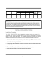
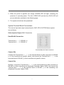
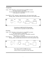
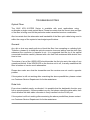
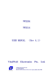
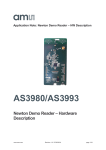
TRANSMITER AND RECEIVER PAIR
SINGLE MODE
XFO1013TRS SERIES
TRANSMITER : XFO1013TS / XFO1013TM
RECEIVER: XFO1013RS / XFO1013RM
1-CHANNEL DIGITALLY ENCODED VIDEO /
1-CHANNEL BI-DIRECTIONAL DATA MULTIPLEXER
USER’S MANUAL
Table Of Contents
General Information……………………………………………. 2
Introduction…………………………………………………… 2
Technical Specifications………………………………….. 2
Installation Instructions………………………………………... 4
Installation Procedure…………………………………….. 4
System Terminal Block Connections…………………. 5
Indicator LEDs………………………………………………. 6
Troubleshooting…………………………………………………. 8
Limited Warranty………………………………………………….9
1
GENERAL INFORMATION
Introduction:
The OXIC XFO-1013TRS Series video and data transmitter and receiver support
simultaneous transmission of one channels of 8-bit digitally encoded video and one
channel of bi-directional data over one multimode and single-mode optical fiber. The
modules are universally compatible with major camera systems and support RS-485
and RS-232 data protocol. Plug and Play design ensures the ease of installation and
electronic and optical adjustments are never required.
Model Number
Unit Type
Model Number
One-channel Digitally Encoded Video/One-channel Data Transmitter
XFO-1013TS
One-channel Digitally Encoded Video/One-channel Data Receiver
XFO-1013RS
Technical Specifications:
VIDEO
Video Input:
Input/Output Channels:
Bandwidth:
Bit Resolution:
Differential Gain:
Differential Phase:
Tilt:
S/N Ratio:
1 volt pk-pk (75 ohms)
1
5 Hz - 8 MHz
8-bit
< 2%
< 0.6°
< 1%
67dB (Weighed)
DATA
Data Interface:
Data Channel:
RS-485/RS-232
2
Data Rate:
Bit Error Rate:
100Kbps
10-9
2
WAVELENGTH
850/1310nm Multimode
1310/1550nm Singlemode
OPTICAL EMITTER:
Laser Diode
NUMBER OF FIBERS
1
CONNECTORS
Optical:
Video:
Data:
ST
BNC
Shield RJ-45 Plug
GENERAL
Power Supply:
Size:
Construction:
MTBF:
Operating Temp:
Storage Temp:
Relative Humidity:
DC12V @ 600mA
195mm x 191mm x 36mm
Aluminum
> 100,000 hours
-30℃ to +50℃
-40℃ to +85℃
0% to 95% (no condensing)
INDICATOR
Module
Blue:
Blue:
Orange :
Video Sync Present
Data Sync Present
Power On
OPTICAL POWER BUDGET
Optical transmission distance is limited to optical loss of the fiber and additional loss
caused by connectors, splices, and patch panels.
3
Fiber
Wavelength
Transmitter
Model
Singlemode
1310nm
XFO1013TS
Receiver
Output
Model
-5 dBm
XFO1013RS
Sensitivity
Optical
Power
Budget
Max
Distance
-26 dBm
21 dB
30km
CAUTION!
The transmitter unit contains a laser-emitting diode located in the optical connector.
This device emits invisible infrared electromagnetic radiation that can be harmful to
human eyes. The radiation from this optical connector, if viewed closely without any
protection, may cause instantaneous damage to the retina of the eye. Direct viewing
of this LED should be avoided at all times.
INSTALLATION INSTRUCTIONS
Installation Procedure
The OXIC XFO-1013TRS video transmission systems series are preset for
immediate use. There are indicator LEDs on the units for monitoring the real-time
status of video, data and power. The following instructions describe the typical
installation procedure and the function of the LED indicators located on each unit.
1. Connect the video source (camera) to the video input BNC connector on the
transmitter unit using coaxial cable.
2. Connect the video output BNC connector on receiver unit to the video monitor using
coaxial cable.
3. Connect the fiber optic cable between the transmitter and receiver
4. Apply the power supply to both the transmitter and receiver
4
5. When the power is applied, the orange POWER LED will light, indicating the
presence of operating power. The blue VIDEO LED and the blue DATA LED will
give an indication as stated in the following page.
6. The system should now be operational.
System Terminal Block Connections
The various input and output connections for OXIC XFO-1013TRS Series system
are as follows:
Video Input or Output: BNC Connectors
Data RS-485 Connection:
Terminal No.1——①: RS-485 (+)
Terminal No.2——②: RS-485 (-)
*Terminal Block for Data Connection
Camera Site
Connect the Terminal No.1——① in the terminal block for data connection to RS-485
(+) of the controlled unit (pan/tilt, dome), and connect the Terminal No.2——② in the
terminal block to RS-485 (-) of the controlled unit (pan/tilt, dome).
Control Site
Similarly, connect the Terminal No.1——① in the terminal block for data connection to
RS-485 (+) of the controlling unit (Keyboard Controller, Matrix, DVR), and connect the
Terminal No.2 — — ② in the terminal block to RS-485 (-) of the controlling unit
(Keyboard Controller, Matrix, DVR).
5
Data RS-232 Connection:
Terminal No.6: Signal being transmitted out over fiber
Terminal No.7: Signal being received in from fiber
Terminal No.8: Ground
*Terminal Block for Data Connection
Camera Site
Connect the Terminal No.7 (232T) in the terminal block connected from the transmitter
to RS-232 (232R) port of the controlled unit (pan/tilt, dome), and Terminal No.8 (GND)
is used for ground connection.
Control Site
Connect the Terminal No.6 (232R) in the data cable from the receiver to RS-232 Port
(232T) of the controlling unit (Keyboard Controller, Matrix, DVR), and the Terminal No.8
(GND) is used for ground connection.
Indicator LEDs
The stand-alone units have integral LEDs that are used to monitor the state of the unit.
There are one video LED, one power LED and four data LEDs on each unit. One,
labeled as “PWR”, lights when operating power is present. Another, labeled as “VID”,
lights when the video input/output signals are detected. The other one, labeled as
“DATA 1, DATA 2, DATA 3, DATA 4”, among them “DATA 2, DATA 3, DATA 4” are
normally on (unavailable), and “DATA 1” blink at the rate of the operating data. As
shown in the diagram in the following,
TRANSMITTER and RECEIVER:
Power: ON: (Orange) Indicates that correct power has been applied
6
Transmitter:
Video: OFF: Indicates no video detected on input BNC connector
(No Video present on input BNC)
ON: (blue) Indicates video detected on input BNC connector
(Video present on input BNC)
Data (DATA1): OFF: Indicates no data detected on the transmit data cable
Blinking: (Blue) Indicates data transmitted at the rate of the operation data.
OPT
PWR
VID IN
VID
DATA
AUDIO
DATA1
DATA3
DATA2
DATA4
*Front Panel of XFO-1013TS (Transmitter)
*Audio RJ-45 Port is expandable for audio tranmission
Receiver:
Video: OFF: Indicates no video present on output BNC connector
(No Video present on output BNC)
ON: (Blue) Indicates video detected on output BNC connector
(Video present on input BNC)
Data (DATA1):
OFF: Indicates no data detected on the receive data cable
Blinking: (Blue) Indicates data received at the rate of the operation data.
OPT
PWR
VID OUT
VID
DATA
AUDIO
DATA1
DATA3
DATA2
DATA4
*Rear Panel of XFO-1013RS (Receiver)
*Audio RJ-45 Port is expandable for audio tranmission
7
TROUBLESHOOTING
Optical Fiber
The OXIC XFO-1013TRS Series is available with most applications using
multimode or single mode optical fibers. Please be certain that the correct size and type
of the fiber is being used for the particular mode transmitter/receiver combination.
Also be certain that the attenuation and bandwidth of the fiber optic cable being used is
within the range of the system’s loss budget specifications.
General
Any dirt or dust may easily pollute or block the fiber from accepting or radiating light.
Therefore, please try to keep the optical connector clear and always use the dust caps
whenever the connector is exposed to air. It is suggested that the tip of the optical
connected should be carefully cleaned with a lint-free cloth moistened with alcohol from
time to time.
The status of any of the VIDEO LED should provide the first clue as to the origin of any
operational failure. If the VIDEO LED on the receiver unit is off, it usually means that the
fiber is broken or has too much attenuation.
Please also make sure that the transmitter and the receiver are not used in opposite
position
If the system is still not working after examining the above possibilities, please contact
our Customer Service Department for further assistance
Data Link
Even when installed exactly as directed, it is possible that the data/audio function may
fail to operate properly. If these problem occurs, first please check the data cable, then
check whether the data cable connector is firmly inserted into the RJ-45 port.
If the system is still not working after examining the above possibilities, please contact
our Customer Service Department for further assistance
8
LIMITED WARRANTY
Tiandy Tech guarantees two (2) year repair at no charge and lift-time maintenance at
prevailing rate from the date of delivery.
Tiandy Tech series products are warranted to be free from defects in materials or
workmanship for one year from the date of retail purchase. We reserve the final right to
judge the malfunction of the products.
What is not covered by this warranty:
Over one-year warranty period
No warranty maintenance for appearance failure
Damage incurred in transportation, loading & unloading or carrying.
Damage resulting from any product modification, alteration or adjustment not
authorized by Tiandy Tech
Damage from misuse, abuse, accident and unsuitable physical and operating
environment.
Maintenance of the accessories such as fuse, one-off battery etc.
Damage from acts of God such as fire, earthquake, lightning, flood etc.
Tiandy Tech reserves the right of final interpretation and modification to the above items.
All the warranty information stated above is subject to change without notice.
9