1
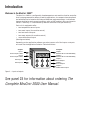
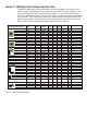
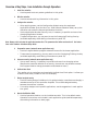
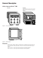
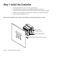
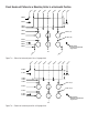
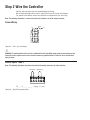
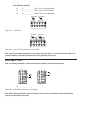
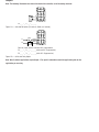
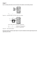
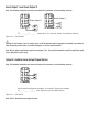
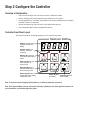
MINICHEF 2000
TM
Fast Start Guide
For All Applications
97
TOTAL
CUSTOMER
SATISFACTION
Watlow Controls
1241 Bundy Blvd.
P.O. Box 5580
Winona, Minnesota U.S.A. 55987-5580
(507) 454-5300, Fax (507) 452-4507
WMC2-XFSN-0008
June 1997
(1116)
ISO 9001
Registered Company
Winona, Minnesota USA
Made in the U.S.A.
Introduction
Welcome to the MINICHEF 2000™
The MINICHEF 2000 is a configurable, time/temperature and machine function controller
that is preprogrammed for dozens of cooking applications. Its compact size and optional
horizontal/vertical orientation facilitates streamlined equipment design. It withstands
rigorous application environment conditions, with an 80ºC ambient rating and superior
EMI/RFI immunity. It is also backed by Watlow’s exclusive three-year warranty.
Each unit is equipped to offer:
•
two temperature sensor inputs
•
two event inputs (for machine control)
•
two heat control outputs
•
two event outputs (for machine control)
•
one audible alarm output
(See diagram below.)
Depending on the application software you select, some or all of the inputs or outputs
are used. See the Application Selection Table that follows.
4 Inputs
5 Outputs
Input 1
Thermocouple or RTD
Output 1
Switched DC or Solid-state Relay
Input 2
Thermocouple or RTD
Event Input 1
G
Output 2
Switched DC or Solid-state Relay
H
A
B
C
D
E
F
Event Input 2
Output 3
Event Output 1
Output 4
Event Output 2
Output 5
Audible Alarm Output
Figure 2 — Inputs and outputs.
See panel 23 for information about ordering The
Complete MINICHEF 2000 User Manual.
MINICHEF™ 2000 Application Software Selection Table
To select the application software that best suits your equipment and purpose, first
locate the type of equipment in the left column, then check the other columns for features and options you need. The application number is on the right (Appl#). Make a
note of the application number. You will be using this number later when programming
your controller. The guide for each application contains specific configuration and programming parameters, and operating instructions. Note that the use of the software
below is not limited to the equipment types listed in the first column.
Intended Equipment Type
(May also apply to other apps)
COOK & HOLD OVENS
Operation
Mode
No. of
Menus
Auto
Auto
Auto
Auto
Manual
Manual
6
17
6
20
N/A
N/A
Heat Output Timed Meat
Channels Zones Probe
Single
Single
Single
Single
Single
Single
1
1
1
1
1
1
Yes
Yes
No
No
Yes
No
Fan
Speeds
1
1
1
1
or 2
2
or 2
2
or 2
2
or 2
2
No
1 or 2
No
1 or 2
Steps
Appl
#
1
2
3
4
5
6
Auto
Auto
Manual
6
15
N/A
Single
Single
Single
1
1
1
No
No
No
1 or 2
4
1 or 2
4
1 or 2 1 or 2
7
8
9
Auto
Auto
Manual
Auto
Auto
Manual
Auto
Auto
Auto
Manual
4
40
N/A
6
40
N/A
6
2/4
40
N/A
Single
Single
Single
Single
Single
Single
Single
Single
Single
Single
1
1
1
1
1
1
1
2
1
1
No
No
No
No
No
No
No
No
No
No
No
No
No
No
No
No
No
No
No
No
1
1
1
1
1
1
1
1
1
1
10
11
12
13
14
15
16
17
18
19
Auto
Manual
Auto
Manual
6
N/A
6
N/A
Dual
Dual
Single
Single
1
1
1
1
No
No
No
No
No
No
No
No
1
1
1
1
20
21
22
23
Auto
Manual
Auto
6
N/A
6
N/A
N/A
Single
6
1
6
No
No
No
No
No
No
1
1
1
24
25
26
Manual & Auto 30
Manual
N/A
Single
Single
1
1
Yes
Yes
CONVECTION OVENS
DEEPFAT FRYERS
Pressurized
Pressurized
Pressurized
GRIDDLES
Clam Shell
Clam Shell
One-sided
One-sided
TIMERS
No temp. control
No temp. control
SHELF TIMER
ROTISSERIE OVENS
Table 3 — Application selection table.
Yes (1) 1 or 2
Yes (1) 1 or 2
27
28
Notes
Overview of Key Steps, from Installation through Operation:
1
Install the controller
•
2
•
3
Use the panel knock-out pattern guidelines in this guide.
Wire the controller
Use the connector/wiring information in this guide.
Configure the controller
•
After applying power, use the Configuration Mode to enter the equipment
Application Number (from the MINICHEF 2000 Software Selection table), set up the
controller and access the thermal optimization functions.
•
Set the Application Number Security Lock, if necessary, to prohibit end users from
changing Application Number.
•
To speed configuration, you may want to use the Prototyping/Training Overlay
(available separately, see Ordering Information on panel 23).
Note: Always select and enter the application number first. The parameters that follow are based on it. See instructions in the Hardware & Software Setup Guide.
4
5
Program the menus (automatic menu applications only)
•
Use the Program Mode to program automatic menus for the chosen application.
•
To ease menu programming, you may want to use the Prototyping/Training Overlay
(available separately, see Ordering Information on panel 23).
Set menu security (automatic menu applications only)
•
6
Set up menu security, if necessary, to prohibit end users from changing values.
(Because the controller defaults to no security, the end user may be able to access
the Program Mode to change parameter values based on menu.)
Set Real-time Clock
This applies only to controllers purchased with the Real-time Clock option. It allows you
to see the time of day instead of “idle” on the display.
7
8
Design faceplate overlay
•
Use the Overlay Design Guidelines in this guide to design, manufacture and apply a
membrane overlay for the controller faceplate. This custom-designed overlay
becomes the end-user interface.
•
For overlay designs to suit specific applications, see the suggestions in each application guide.
Operate the MINICHEF 2000
•
Use the Operation Mode to run the installed controller. This is the default mode.
Operation instructions are included in each application guide (available separately,
see ordering information on back page).
General Description
Getting to know your MINICHEF™ 2000
Front view
Back view
Shown with mating connector terminals installed.
Mating connectors and terminals are purchased
separately.
2.00 in.
IIIIIIIIII IIIIIII IIIIIIIIII IIIIIIII
OPER. RANGE 0-80 DEG C
2=OC+
3=OC35=OC+
6=OC48=EI1+
9=ALARM
G
H
A
B
C
D
E
F
11=EI2+
12=EI113=L2 24V
14=L1 24V
15=EI2-
3.00 in.
NSF
c
13
10
7
4
1
14
11
8
5
2
15
12
9
6
3
WATLOW
CONTROLS
INPUT#1 NOT INPUT#2 NOT
TC+ TC- USED TC+ TC- USED
3.00 in.
Figure 5a — Front and back view.
3.25 in.
4.13 in.
Mounting collar
Figure 5b — Mounting collar.
Dimensions:
Overall width x height x depth (Includes MINICHEF 2000 with mounting collar and
space required for mating connectors. Does not include wire bundle space requirements):
4.13 in x 3.25 in x 2.00 in (with collar mounted in horizontal position)
3.25 in x 4.13 in x 2.00 in (with collar mounted in vertical position)
Step 1 Install the Controller
•
Select sheet metal (16-, 18-, 20- or 22- gauge panel).
•
For panel knock-out patterns, see subsequent pages of this guide.
•
Use #6-32 mounting studs x 0.50” length minimum, either pressed or welded.
•
Install the unit with either a horizontal or vertical mounting collar position.
•
Install mating connectors to unit.
Note: This device should be used in systems that incorporate a separate high limit device for safety.
Mounting Collar
in horizontal position
MINICHEF 2000 Controller
Panel showing recommended knock-out pattern
Figure 6 — Mounting the MINICHEF 2000.
in
.
1.
87
5
in
.
in
.
1.
40
5
in
.
1.
00
0
in
.
0.
50
0
in
.
0.
00
0
in
.
0.
50
0
in
.
1.
00
0
1.
40
5
1.
87
5
in
.
Panel Knock-out Pattern for a Mounting Collar in a Horizontal Position
2.535 in.
2.125 in.
.875 in. ref
1.660 in.
1.530 in.
1.250 in.
ø0.53 in. (6)
0.875 in.
ø0.135 in. (10)
0.375 in.
0.125 in.
0.000 in.
#6-32 stud (4)
minimum recommended
length 0.50 in.
0.250 in.
1.
1.
37
37
5
5
in
in
.
.
C/L
.
in
.
.
5
87
1.
1.
33
8
0
in
in
.
00
1.
0.
50
0
in
.
in
.
0.
00
0
in
.
in
0
0
50
0.
00
1.
7
33
1.
1.
87
5
in
in
.
.
Figure 7a — Pattern for horizontal panel 16- or 18-gauge thick.
2.462 in.
2.125 in.
.800 in. ref
1.662 in.
1.530 in.
1.250 in.
ø0.53 in. (6)
0.875 in.
ø0.135 in. (8)
0.375 in.
0.125 in.
0.000 in.
#6-32 stud (4)
minimum recommended
length 0.50 in.
C/L
Figure 7b — Pattern for horizontal panel 20- or 22-gauge thick.
.
.
1.
40
5
in
.
1.
00
0
in
.
0.
50
0
in
.
0.
00
0
in
.
in
0.
50
0
in
1.
00
0
1.
40
5
in
.
Panel Knock-out Pattern for a Mounting Collar in a Vertical Position
3.000 in.
2.535 in.
.875 in. ref
1.660 in.
1.530 in.
1.250 in.
ø0.53 in. (6)
0.875 in.
ø0.135 in. (10)
0.375 in.
0.000 in.
0.250 in.
0.750 in.
.
in
in
0
5
1.
1.
37
00
.
.
in
in
0
5
00
37
1.
1.
.
C/L
#6-32 stud (4)
minimum recommended
length 0.50 in.
.
.
in
8
33
1.
1.
00
0
in
.
.
in
0
50
0.
0.
00
0
in
.
0.
50
0
in
.
in
0
00
1.
1.
33
7
in
.
Figure 8 — Pattern for vertical panel 16- or 18-gauge thick.
3.000 in.
2.462 in.
.800 in. ref
1.662 in.
1.530 in.
1.250 in.
ø0.53 in. (6)
0.875 in.
ø0.135 in. (8)
0.375 in.
0.000 in.
0.750 in.
Figure 8 — Pattern for vertical panel 20- or 22-gauge thick.
.
in
0
00
1.
1.
00
0
in
.
C/L
#6-32 stud (4)
minimum recommended
length 0.50 in.
Step 2 Wire the Controller
Position the connector with the beveled edges at the top.
Not all software applications use or require wiring to all inputs and outputs.
For specific information consult the guide for the application you are using.
Note: The following illustration is a view of the back of the controller, not of the mating connector.
Power Wiring
Fuse
L1
L2
13
14
13
14
15
10
11
12
7
8
9
4
5
6
1
2
3
Figure 9a — 24VÅ (ac) Low Voltage.
Ó
WARNING: To avoid potential electric shock, use National Electric Code (NEC) safety practices when wiring and connecting this unit to a power source and to electrical sensors of peripheral devices. Failure to do so could result in
injury or death.
Sensor Inputs 1 and 2
Note: The following illustrations are views of the back of the mating connector, not of the controller.
Input 1 Wiring
1
1
Input 2 Wiring
4
2
2
3
4
5
5
6
F 2 _ _ – 1 _ _ _ - _ _ _ _ (Type J, K, or E).
Figure 9b — Dual Thermocouple Option.
Dual RTD Option (platinum)
F2__–2___–____
(100Ω RTD, curve selectable)
F2__–3___-____
(500Ω RTD, curve selectable)
F2__–4___-____
(1000Ω RTD, curve selectable)
Input 1 Wiring
S1
Input 2 Wiring
S2
1
S1
2
3
S2
4
5
6
Figure 10a — 2-wire RTD.
Input 1 Wiring
S1
S2
1
2
S3
Input 2 Wiring
S1
3
S2
4
S3
5
6
Figure 10b — 3-wire RTD: (will function as a 2-wire RTD).
Note: If your chosen software application does not require two sensor inputs, it is not necessary to wire Input 2. For
specific information, consult the application guide for the application you are using.
Event Inputs 1 and 2
Note: The following illustration is a view of the back of the controller, not of the mating connector.
13
14
15
13
14
15
10
11
12
12
10
11
12
7
8
9
8
7
8
9
4
5
6
4
5
6
1
2
3
1
2
3
Event Input 1
15
11
Event Input 2
F2__-____-____
Figure 10c — Switched DC (two per unit, non-isolated).
Note: Not all software applications require event inputs 1 and 2. For specific information consult the application
guide for the application you are using.
Output 1
Ext. Load
Note: The following illustrations are views of the back of the controller, not of the mating connector.
4
1
13
14
15
10
11
12
7
8
9
4
5
6
1
2
3
F2__–_1__–____
Figure 11a — Switched DC Option (5V nominal, 30mA, non-isolated).
Fuse
L1
Com 4
NO 1
L2
13
14
15
10
11
12
7
8
9
4
5
6
1
2
3
Ext. Load
Form A, 0.4A, with or without RC Suppression
F 2 _ _ – _ 2 _ _ – _ _ _ _ (without RC Suppression)
F 2 _ _ – _ 3 _ _ – _ _ _ _ (with RC Suppression)
Figure 11b — Solid-state Relay Option.
Note: Not all software applications require Output 1. For specific information consult the application guide for the
application you are using.
Output 2
Ext. Load
Note: The following illustrations are views of the back of the controller, not of the mating connector.
10
7
13
14
15
10
11
12
7
8
9
4
5
6
1
2
3
F2__-__1_–____
Figure 12a — Switched DC Option (5V nominal, 30mA, non-isolated).
Fuse
L1
Com 10
NO
L2
7
13
14
15
10
11
12
7
8
9
4
5
6
1
2
3
Ext. Load
Form A, 0.4A, with or without RC Suppression
F 2 _ _ - _ _ 2 _ - _ _ _ _ (without RC Suppression)
F 2 _ _ - _ _ 3 _ - _ _ _ _ (with RC Suppression)
Figure 12b — Solid-state Relay Option.
Note: Not all software applications require Output 2. For specific information consult the application guide for the
application you are using.
Event Output 1 and Event Output 2
Note: The following illustrations are views of the back of the controller, not of the mating connector.
14
15
13
14
15
10
11
12
10
11
12
7
8
9
7
8
9
4
5
6
4
5
6
1
2
3
1
2
3
Event Output 1
2
Ext. Load
3
F2__-___1-____
Event Output 2
6
5
Ext. Load
13
(switched dc, 5V nominal, 30mA, non-isolated outputs)
Figure 13a — Event Outputs.
ç
Warning: If event outputs 1 & 2 are used to cause or initiate machine motion, appropriate reasonable care should be
taken to prevent personal injury or machine damage as a result of machine motion.
Note: Not all software applications require event outputs 1 & 2. For specific information consult the application guide
for the application you are using.
Output 5: Audible Alarm Output Signal Option
Note: The following illustrations are views of the back of the controller, not of the mating connector.
14
15
10
11
12
7
8
9
4
5
6
1
2
3
9
5
Ext. Load
13
Alarm signal available at connector, 5V nominal, 30ma, non-isolated.
F 2 _ _ - _ _ _ _ - _ 0 _ _ (unit without internal audible alarm)
Figure 13c — Switched DC.
Note: Pin 5 is shared with event output 2 wiring.
Step 3 Configure the Controller
Overview of Configuration
•
Get to know the keys and how they function in different modes.
•
Review configuration and programming procedures in this guide.
•
Choose applications, functions, parameters and values (see Application Software
Selection Table in this guide).
•
Review the operating instructions (in each application guide).
•
Get a complete idea of how the application works.
Controller Front Panel Layout
During configuration and programming, this is how the keys work:
MINICHEF 2000
Display Five-digit, sevensegment numeric LED
display.
Indicator lights (1 for
each key, 2 for heat
channels).
G
A
Edit key (A) Access the
next level of parameters or
values.
Enter key (B) Enter the
value and return to
previous level.
Home key (D) Move to
Operation Mode with a
two-second key press.
Escape key (E) Return to
original value when editing
a parameter value.
H
B
Edit
D
Home
C
Enter
E
F
Escape
Up key (C) Move Down key (F) Move
up the lists.
down the lists.
Note: To order this helpful Prototyping/Training Overlay, see Ordering Information on panel 23.
Note: In the Operation Mode, the keys will function differently, depending on the chosen application number. For
more information, see individual application guides.
Software Structure
The MINICHEF 2000 software uses three modes — Configuration Mode, Programming
Mode and Operation Mode — and each mode contains up to three levels of functions,
parameters and values. The Operation Mode is the default mode.
MINICHEF 2000
[M``1]
G
A
From the Menu
Programming
Mode, press the
Home and Escape
keys for two
seconds to view the
functions.
FUNCTIONS
Press the Up- or
Down-arrow key to
scroll through the
functions.
H
C
B
Edit
Enter
D
F
E
Home
Escape
Press the Enter
key to return to
idle.
[EtyPE]
[SEtUP]
[tHErL]
B
Enter
D
Home
•
•
•
Press the Home
key for three
seconds to return
to idle.
Press the Edit key to
view the parameters of
the selected function.
A
Edit
The display switches
between the parameter
and its value.
PARAMETERS
Press the Up- or
Down-arrow key to
scroll through the
parameters and their
values.
Press the Edit key to
display the values of
the selected
parameter.
[APPL~]
[A_Loc]
[Sound]
Press the Enter key to
return to the menus.
[``32Ï]
D
Home
Press the Home key for
two seconds to return to
idle.
A
Edit
Press the Enter key
to save the new
value and return to
the parameters.
VALUES
Press the Up- or
Down-arrow key to
scroll through the
range of values.
[``~~1]
[````2]
[````3]
•
•
•
Figure 15 — Navigating in Configuraton Mode.
B
Enter
B
Enter
E
Escape
Press the Escape key to
return to the parameters
without saving the new
value.
MINICHEF 2000
[`idle]
G
A
From the Operation
Mode, press the
Up- and Downarrow keys for two
seconds to view the
menus.
H
C
B
Edit
Enter
D
F
E
Home
Escape
Press the Enter
key to return to
idle.
MENUS
Press the Up- or
Down-arrow key to
scroll through the
menus.
[M``1]
[M``2]
[M``3]
B
Enter
D
Home
•
•
•
Press the Home
key for three
seconds to return
to idle.
Press the Edit key to
view the parameters of
the selected menu.
A
Edit
The display switches
between the parameter
and its value.
PARAMETERS
Press the Up- or
Down-arrow key to
scroll through the
parameters and their
values.
Press the Edit key to
display the values of
the selected
parameter.
[stPt2]
[tinE2]
[FAn`2]
Press the Enter key to
return to the menus.
[``32Ï]
D
Home
Press the Home key for
two seconds to return to
idle.
A
Edit
Press the Enter key
to save the new
value and return to
the parameters.
VALUES
Press the Up- or
Down-arrow key to
scroll through the
range of values.
[``32Ï]
[``33Ï]
[``34Ï]
•
•
•
Figure 16 — Navigating in Menu Programming Mode.
B
Enter
B
Enter
E
Escape
Press the Escape key to
return to the parameters
without saving the new
value.
■ 17
NOTES
Watlow Controls
Watlow Controls is a division of Watlow Electric Mfg. Co., St. Louis, Missouri, a manufacturer of industrial electric heating products since 1922. Watlow begins with a full set
of specifications and completes an industrial product that is manufactured totally inhouse, in the U.S.A. Watlow products include electric heaters, sensors, controls and
switching devices. The Winona operation has been designing solid state electronic control devices since 1962, and has earned the reputation as an excellent supplier to original equipment manufacturers. These OEMs depend upon Watlow Controls to provide
compatibly engineered controls that they can incorporate into their products with confidence. Watlow Controls resides in a 100,000-square-foot marketing, engineering and
manufacturing facility in Winona, Minnesota.
Technical Assistance
If you encounter a problem with your Watlow controller, refer to the Troubleshooting
Chart in this guide. Also review all of your configuration information for each step of
the setup to verify that your selections are consistent with your applications.
If the problem persists after checking all the steps, you can get technical assistance by
calling Watlow Controls at (507) 454-5300, between 7 a.m. and 5 p.m. CST, and asking
for an applications engineer. When you call have the following information on hand: the
controller’s part number, date code, serial number, software revision number, and application number. Much of this information is available on the controller case. All of this
information is also available via the MINICHEF 2000 main display by accessing the
WatHelp Diagnostics Function under [`diag] in the Configuration Mode.
We Value Your Feedback
Your comments and suggestions on this manual are welcome. Please send them to,
Technical Writer, Watlow Controls, 1241 Bundy Blvd., P.O. Box 5580, Winona, MN
55987-5580 or call (507) 454-5300 or fax (507) 452-4507.
Contact
•
•
•
•
•
Phone: (507) 454-5300.
Fax: (507) 452-4507.
For technical support, ask for an Applications Engineer.
To place an order, ask for Customer Service.
To discuss a custom option, ask for the MINICHEF 2000 Product Manager.
Warranty
The MINICHEF 2000 is warranted to be free of defects in material and workmanship for
36 months after delivery to the first purchaser for use, providing that the unit has not
been misapplied. Since Watlow has no control over its use, or misuse, we cannot guarantee against failure. Watlow's obligations hereunder, at Watlow's option, are limited to
replacement or refund of purchase price of a unit which upon examination proves to be
defective within the warranty period. This warranty does not apply to damage resulting
from transportation, alteration, misuse, or abuse.
Returns
• Call or fax Customer Service for a Return Material Authorization (RMA) number
before returning a control.
• Put the RMA number on the shipping label, and also on a description of the problem.
• 20% of net price restocking charge applies to all standard units returned to stock.
Note: All documentation of the MINICHEF 2000 is subject to change without notice.
Specifications (1032)
Control Mode
1
• Single and dual heat channels, PID or on/off.
• Microprocessor-based, programmable, reverse-acting
control outputs.
• User-selectable embedded application software defines
operation of display, keys, inputs, outputs, timing
action.
• One-step auto-tuning, WatHelp diagnostics, WatCurve
temperature compensation.
Agency
• CE approved:
89/336/EEC Electromagnetic Compatibility Directive
-EN 50081-1: Emissions
-EN 50082-1: Immunity
73/23/EEC Low-Voltage Directive
-EN 60730-1 and EN 60730-2-9: Safety
• NSF Listed, Criteria 2.5
• AGA: UL tested to AGA standard Z21.23, UL File
#E43684.
• UL and C-UL recognized, UL 197, 873, 991 and CSA
standard C22.2-24, File # E43684.
Operator Interface
• Membrane overlay, contamination and water resistant,
(supplied by customer).
• LED display, 5-digit, 0.56 in high, red.
• Displays times, temperatures, user prompts and
diagnostic codes.
• User-selectable time and temperature display formats.
• Temperature display formats—˚F or ˚C.
• Time display formats—H:MM:SS, HH:MM, or MMM:SS.
• 8 discrete indicator LEDs, red.
• 6 tactile feedback keys.
• Menu-driven operation and manual modes available.
• WatHelp diagnostics.
• Real-time clock option displays time of day.
Accuracy
2
• Calibration accuracy and sensor conformity : ± 2.0°F
for Type J thermocouple and RTD, ± 0.35% of span for
Type K and E thermocouples, ±1 LSD, 77°F ± 5°F
ambient and rated line voltage of ±10%.
• Accuracy span: 1000°F (540°C) minimum.
• Temperature stability: ± 0.15˚F/ ˚F (0.15˚C/˚C) change
in ambient typical.
Sensors / Inputs
• Contact inputs, TTL compatible with internal pull-up
resistor, two available.
3
• Thermocouple, software selectable Type J, K or E,
32 to 1200°F. (Dual-channel applications require at
least one ungrounded thermocouple).
3
• RTD, 2- or 3-wire, platinum, 100, 500, 1000Ω, at 0°C,
software selectable DIN or JIS curves, 0 to 1200°F
(3-wire will function as 2-wire).
• Input A / D resolution: 15 bit.
Output Options
• Solid-state relay, 0.4A, with or without contact suppression.
• Switched dc signal, 4.5V to 5.25V, 30mA maximum
output, minimum load resistance > 150Ω, non-isolated.
Audible Output Options
• Switched dc signal, 4.5V to 5.25V, 30mA maximum
output, minimum load resistance > 150Ω, non-isolated.
• Internal audible alarm, 75dB at 10 cm.
Connectors
4
• Sensor Input Terminal Strip : RIACON, 6-position,
quick-connect.
4
• Power Supply & Input / Output Terminal : AMP,
15-position, quick-connect.
Power / Line Voltage
• 20.4 to 26.4VÅ (ac), 47 to 63Hz.
• 15VA maximum.
• For CE applications, input power must be limited to
15W external to the control.
• Program retention upon power failure via non-volatile
memory.
• Battery / real-time clock option: 6-year lithium battery,
provides power backup upon power failure, operation
resumption after power recovery, ability to display time
of day.
Operating Environment
• 32 to 176°F (0 to 80°C), 0 to 90% RH, non-condensing.
Storage Temperature
• -40 to 176°F (-40 to 80°C).
Mechanical
• Case: polycarbonate Lexan with adjustable mounting
collar (vertical or horizontal orientation), designed for
mounting on 16-, 18-, 20- and 22-gauge panels.
• Internal panel mounting requires a specified panel
cutout and four #6-32 studs or equivalent.
• Overall width x height x depth: horizontal - 4.13 in x
3.25 in x 2.00 in; vertical - 3.25 in x 4.13 in x 2.00 in
(Assumes mating connectors are attached. Does not
include wire bundle space requirements.).
• Vibration: 2g, 10 to 150Hz, applied in any one of three
axes.
• Weight: 6.50oz maximum.
Program Storage
• All non-embedded user and factory programs are
stored in non-volatile memory. Can be changed by
reprogramming.
Sample/Update Rates
• 1 input: 4Hz.
• 2 inputs: 4Hz.
• PID: 1Hz.
• Control outputs: 100Hz.
• Display: 10Hz.
1
The MINICHEF 2000 controller is to be used in systems with an
external high temperature limiting device.
2
Thermocouple lead resistance of 200Ω causes < 1°C error. RTD, 22
gauge wire will not contribute more than 0.086°F error / ft.
3
Dual channel applications require either two thermocouple sensors or two identical RTD sensor types.
For mating connector information, see Ordering Information
Accessory section.
4
5
Certified for thermometer accuracy (oven and hot food holding
applications from 32°F to 60°F) when used with RTD or type J
thermocouple probes.
Ordering Information
(1033)
F 2 HA- _ _ _ 1 - _ _AA
MINICHEF™ 2000
Cooking controller with numerous food
equipment application software sets,
single and dual channel on/off or PID
temperature regulation, timer and
machine-function control, microprocessorbased, programmable, auto-tuning,
WatCurve™, WatHelp diagnostics,
24VÅ (ac) power input, agency approved,
flush mounted (membrane faceplate
supplied by customer).
Inputs
1 = Dual thermocouple, Type J, K or E
2 = Dual RTD, platinum, 100Ω, curve
selectable
3 = Dual RTD, platinum, 500Ω, curve
selectable
4 = Dual RTD, platinum, 1000Ω, curve
selectable
Note: All models include two event inputs,
switched dc logic signal, non-isolated.
Output Number 1
1 = Switched dc, 5V nominal, 30mA,
non-isolated
2 = Solid-state relay, Form A, 0.4A,
without RC suppression
3 = Solid-state relay, Form A, 0.4A,
with RC suppression
Output Number 2
1 = Switched dc, 5V nominal, 30mA,
non-isolated
2 = Solid-state relay, Form A, 0.4A,
without RC suppression
3 = Solid-state relay, Form A, 0.4A,
with RC suppression
Event Outputs 1 and 2
1 = 2 event outputs, switched dc, 5V nominal,
30mA, non-isolated
Battery and Real-time Clock
0 = None
1 = Includes battery and real-time clock
Audible Alarm
0 = Alarm signal available at connector,
switched dc, 5V nominal, 30mA, non-isolated
1 = Internal alarm included
Software
AA = Standard Food Equipment Application
Software Set
XX = Custom Set-up parameters or Made-To-Order
custom software. Consult your local Watlow
Sales Engineer. Code number assigned by factory.
■ 21
NOTES
Declaration of Conformity
WATLOW CONTROLS
1241 Bundy Boulevard
Winona, Minnesota 55987 USA
97
MINICHEF 2000
Declares that the following product:
English
Designation:
MINICHEF 2000
Model Number(s):
F2(H or U)(A or C)-(1, 2, 3 or 4)(1, 2 or 3)(1, 2 or 3)
1-(0 or 1)(0 or 1)(Any two letters or numbers)
Classification:
Electronic incorporated Class III temperature
controller, Type 2C action, for use in light industrial
RatedVoltage:
24V~ (VAC)
Rated Frequency:
50/60 Hz
Maximum Input Power:
15 Watts
Meets the essential requirements of the following European Union Directive(s)
using the relevant section(s) of the normalized standards and related documents
shown:
89/336/EEC Electromagnetic Compatibility Directive
EN 50082-1:
EN 61000-4-2:
EN 61000-4-4:
EN 61000-4-5:
EN 61000-4-6:
EN 61000-4-8:
EN 61000-4-11:
ENV 50140:
ENV 50204:
EN 50081-1:
EN 55011:
1995 EMC Generic immunity standard, Part 1: Residential,
commercial and light industry
Electrostatic discharge
Electrical fast transients
Surge immunity
Conducted immunity
Power frequency magnetic field immunity
Voltage dips, short interruptions and voltage variations
immunity
1994 Radiated immunity
1995 Cellular phone
1994 EMC Generic emission standard, Part 1: Residential,
commercial and light industry
1991 Limits and methods of measurement of radio disturbance
characteristics of industrial, scientific and medical radiofrequency equipment (Class B)
1995
1995
1995
1996
1993
1994
73/23/EEC Low-Voltage Directive
EN 60730-1:
1993 Automatic electrical controls for household and similar
use, Part 1: General requirements
EN 60730-2-9: 1995 Automatic electrical controls for household and similar use,
Part 2; Particular requirementsSection 2.9 Temperature
sensing controls
Déclare que le produit suivant :
Français
Désignation :
MINICHEF 2000
Numéro(s) de modèle(s) : F2 (H ou U) (A ou C)-(1, 2, 3 ou 4) (1, 2 ou 3)(1, 2 ou
3) 1-(0 ou 1) (0 ou 1) (deux lettres ou chiffres
quelconques)
Classification :
Contrôleur de température Classe III électronique,
action type 2C, pour les utilisations industrielles
légères
Tension nominale :
24 V ~ (alternatif)
Fréquence nominale :
50/60 Hz
Alimentation
d’entrée maximale :
15 W
Conforme aux exigences de la (ou des) directive(s) suivante(s) de l’Union
Européenne figurant aux sections correspondantes des normes et documents
associés ci-dessous :
89/336/EEC Directive de compatibilité électromagnétique
EN 50082-1 :
1995 Norme générique sur l’immunité, Partie 1 :
Environnement résidentiel, commercial et industriel
léger
Décharge électrostatique
Transitoires rapides électriques
Immunité aux surtensions
Immunité conduite
Immunité aux champs magnétiques de fréquence
industrielle
EN 61000-4-11 : 1994 Immunité aux chutes de tension, brèves interruptions et
variations de tension
ENV 50140 :
1994 Immunité rayonnée
ENV 50204 :
1995 Téléphone cellulaire
EN 50081-1 : 1994 Norme générique sur les émissions, Partie 1 :
Environnement résidentiel,commercial et industriel
léger
EN 55011 :
1991 Limites et méthodes de mesure des caractéristiques des
perturbations radioélectriques des appareils industriels,
scientifiques et médicaux (Classe B)
EN 61000-4-2 :
EN 61000-4-4 :
EN 61000-4-5 :
EN 61000-4-6 :
EN 61000-4-8 :
1995
1995
1995
1996
1993
73/23EEC Directive sur les basses tensions
EN 60730-1 :
1993 Commandes électriques automatiques à usage
domestique et similaire, Partie 1: Exigences générales
EN 60730-2-9 : 1995 Commandes électriques automatiques à usage domestique
et similaire, Partie 2: Exigences particulières, Section 2.9
Commandes de détection de la température
WMC2-XCEM
Erklärt, daß das folgende Produkt:
Deutsch
Beschreibung:
MINICHEF 2000
Modellnummer(n):
F2 (H oder U)(A oder C)-(1, 2, 3 oder 4)(1, 2 oder 3)(1, 2
oder 3) 1-(0 oder 1)(0 oder 1)(2 beliebige Buchstaben oder
Zahlen)
Klassifikation:
Eingebautes elektronisches Temperaturregelsystem der
Klasse III, Typ 2C Aktion, für den Einsatz in der
Leichtindustrieumwelt
Nennspannung:
24 V~ (V Wechselstrom)
Nennfrequenz:
50/60 Hz
Maximaler
Leistungsverbrauch: 15 W
Erfüllt die wichtigsten Normen der folgenden Anweisung(en) der Europäischen
Union unter Verwendung des wichtigsten Abschnitts bzw. der wichtigsten
Abschnitte der normalisierten Spezifikationen und der untenstehenden
einschlägigen Dokumente:
89/336/EEC EWG Elektromagnetische Verträglichkeit
EN 50082-2:
EN 61000-4-2:
EN 61000-4-4:
EN 61000-4-5:
EN 61000-4-6:
EN 61000-4-8:
EN 61000-4-11:
ENV 50140:
ENV 50204:
EN 50081-2:
EN 55011:
1995 EMC-Rahmennorm für Störsicherheit, Teil 1:
Wohngegenden, Handelsverkehr und Leichtindustrie
Elektrostatische Entladung
Elektrische schnelle Stöße
Spannungsstoßimmunität
Störimmunität
Magnetische Felder
Immunität gegen Spannungsgefälle, kurze Unterbrechungen
und Spannungsabweichungen
1994 Strahlungsimmunität
1995 Mobiltelefon
1994 EMC-Rahmennorm für Emissionen, Teil 1:
Wohngegenden, Handelsverkehr und Leichtindustrie
1991 Beschränkungen und Methoden der Messung von
Funkstörungsmerkmalen industrieller, wissenschaftlicher
und medizinischer Hochfrequenzgeräte (Klasse B)
1995
1995
1995
1996
1993
1994
72/23/EEC EWG
Niederspannungsrichtlinie
EN 60730-1:
1993 Automatische elektrische Regelsysteme für den
Haushalt und ähnlichen Einsatz, Teil 1: Allgemeine
Richtlinien
EN 60730-2-9: 1995 Automatische elektrische Regelsysteme für den Haushalt
und ähnlichen Einsatz, Teil 2: Spezifische Richtlinien
Abschnitt 2.9, Temperaturregelsysteme
Declara que el producto siguiente:
Español
Designación:
MINICHEF 2000
Números de modelo:
F2 (H o U)(A o C)-(1, 2, 3 ó 4)(1, 2 ó 3)(1, 2 ó 3) 1-(0
ó 1)(0 ó 1)(Cualquier combinación de dos letras o
números)
Clasificación:
Control de temperatura electrónico incorporado,
Clase III, acción tipo 2C, para uso en aplicaciones de
industria ligera
Tensión nominal:
24 V ~ (Vca)
Frecuencia nominal:
50/60 Hz
Potencia de
entrada máxima:
15 vatios
Cumple con los requisitos esenciales de las siguientes Directivas de la Unión
Europea, usando las secciones pertinentes de las reglas normalizadas y los
documentos relacionados que se muestran:
89/336/EEC - Directiva de Compatibilidad Electromagnética
EN 50082-1:
EN 61000-4-2:
EN 61000-4-4:
EN 61000-4-5:
EN 61000-4-6:
EN 61000-4-8:
EN 61000-4-11:
ENV 50140:
ENV 50204:
EN 50081-1:
EN 55011:
1995 Norma de inmunidad genérica del EMC, Parte 1:
Ambiente residencial, comercial e industria ligera
Descarga electrostática
Perturbaciones transitorias eléctricas rápidas
Sobretensión
Inmunidad conducida
Campos magnéticos
Caídas de tensión, interrupciones breves y variaciones de
tensión
1994 Inmunidad radiada
1995 Teléfono portátil
1994 Norma de emisión genérica del EMC, Parte 1: Ambiente
residencial, comercial e industria ligera
1991 Límites y métodos de medición de características de
perturbaciones de radio correspondientes a equipos de
radiofrecuencia industriales, científicos y médicos (Clase B)
1995
1995
1995
1996
1993
1994
73/23/EEC Directiva de Baja Tensión
EN 60730-1:
1993 Controles eléctricos automáticos para
electrodomésticos y aparatos de uso similar, Parte 1:
Requerimientos generales
EN 60730-2-9: 1995 Controles eléctricos automáticos para electrodomésticos y
aparatos de uso similar, Parte 2: Requerimientos
particulares Sección 2.9, Controles para detección de
temperatura
Erwin D. Lowell
Name of Authorized Representative
Winona, Minnesota, USA
Place of Issue
General Manager
Title of Authorized Representative
March, 1997
Date of Issue
________________________________________
Signature of Authorized Representative
(1031)
Part Numbers & Accessories
MINICHEF 2000 Accessories
0836-0442-0000
A001-0298-0000
0238-0679-0000
0830-0479-0000
A001-0249-0001
A001-0249-0002
Sensor Input Mating Connector,
(RIACON #31007106), 6-position,
quick-connect terminal, screw
connection for 28-14 AWG wires,
tighten to 7 in/lb
Power Supply and I / O Mating
Connector Kit. Includes:
– 1 AMP #1-640523-0, 15-position,
quick-connect terminal
– 15 AMP #641300-1 crimp pins
Prototyping & Training Membrane
Overlay, adhesive-backed,
4.75 in x 4.75 in
Prototyping EPROM Extraction Tool,
AMP #821980-1
120VÅ to 24VÅ (ac), stepdown
transformer, class 2, quick-connect
terminals included
208 / 240 VÅ to 24 VÅ (ac), stepdown transformer, class 2, quickconnect terminals included
Recommended Sources of Supply
for Miscellaneous Items
DURA-TECH, Inc.
LaCrosse, WI
(608) 781-2570
•Custom Membrane Faceplates
AMP, Inc.
Harrisburg, PA
1-800-522-6752
•Prototyping EPROM Extraction
Tool Part No. 821980-1
•Pin Crimping Hand Tools
Part No. 90325-1 or 58514-1
•Pin Extraction Hand Tool
Part No. 455822-2
RIA Electronic, Inc.
Eatontown, NJ
(908) 389-1300
•RIACON Connectors
MINICHEF 2000 Documentation
WMC2-XUGN-0000
WMC2-XADN-0000
WMC2-XTDN-0000
WMC2-XSGN-0000
WMC2-XAGN-0001
WMC2-XAGN-0002
WMC2-XAGN-0003
WMC2-XAGN-0004
WMC2-XAGN-0005
WMC2-XAGN-0006
WMC2-XAGN-0007
The Complete MINICHEF
2000 User Guide
The Complete MINICHEF
2000 User Guide on CD
MINICHEF 2000 Tutorial
Disk
Hardware & Software
Setup Guide
Cook-&-Hold Oven
Application Guide
Convection Oven
Application Guide
Deepfat Fryer Application
Guide
Griddle Application Guide
Timer Application Guide
Shelf Timer Application
Guide
Rotisserie Oven
Application Guide


![Descargar - index [revista.cnic.edu.cu]](http://vs1.manualzilla.com/store/data/006273898_1-89efab09a622fdfc6ec934b030e2e15f-150x150.png)