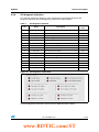
1
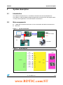
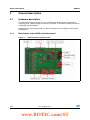
UM0759
User manual
L9958 evaluation board and graphical user interface (GUI)
1
Overview
This document was intended to explain how to work with L9958 GUI and ST10F276
evaluation board.
July 2009
Doc ID 16058 Rev 1
1/26
www.st.com
www.BDTIC.com/ST
Contents
UM0759
Contents
1
Overview . . . . . . . . . . . . . . . . . . . . . . . . . . . . . . . . . . . . . . . . . . . . . . . . . . 1
2
System description . . . . . . . . . . . . . . . . . . . . . . . . . . . . . . . . . . . . . . . . . . 5
3
2.1
Introduction . . . . . . . . . . . . . . . . . . . . . . . . . . . . . . . . . . . . . . . . . . . . . . . . 5
2.2
Main components . . . . . . . . . . . . . . . . . . . . . . . . . . . . . . . . . . . . . . . . . . . . 5
General description . . . . . . . . . . . . . . . . . . . . . . . . . . . . . . . . . . . . . . . . . . 6
3.1
Main feature of the L9958 evaluation board . . . . . . . . . . . . . . . . . . . . . . . 6
3.1.2
Battery power supply . . . . . . . . . . . . . . . . . . . . . . . . . . . . . . . . . . . . . . . . 8
3.1.3
L9958 H-bridge DC motor driver . . . . . . . . . . . . . . . . . . . . . . . . . . . . . . . 8
3.1.4
DC motor connector . . . . . . . . . . . . . . . . . . . . . . . . . . . . . . . . . . . . . . . . . 9
3.1.5
Jumpers . . . . . . . . . . . . . . . . . . . . . . . . . . . . . . . . . . . . . . . . . . . . . . . . . . 9
3.1.6
Test points . . . . . . . . . . . . . . . . . . . . . . . . . . . . . . . . . . . . . . . . . . . . . . . 11
3.1.7
I/O header . . . . . . . . . . . . . . . . . . . . . . . . . . . . . . . . . . . . . . . . . . . . . . . 11
3.1.8
BOM of L9958 evaluation board . . . . . . . . . . . . . . . . . . . . . . . . . . . . . . 12
ST10F276 evaluation board configuration . . . . . . . . . . . . . . . . . . . . . . . . 12
3.3
Evaluation GUI description . . . . . . . . . . . . . . . . . . . . . . . . . . . . . . . . . . . . 13
Appendix A
2/26
3.1.1
3.2
3.4
4
Hardware description . . . . . . . . . . . . . . . . . . . . . . . . . . . . . . . . . . . . . . . . . 6
3.3.1
RUN and STOP L9958 GUI . . . . . . . . . . . . . . . . . . . . . . . . . . . . . . . . . . 13
3.3.2
Configure L9958 GUI . . . . . . . . . . . . . . . . . . . . . . . . . . . . . . . . . . . . . . . 13
3.3.3
Rx error . . . . . . . . . . . . . . . . . . . . . . . . . . . . . . . . . . . . . . . . . . . . . . . . . 20
3.3.4
"Exit" button . . . . . . . . . . . . . . . . . . . . . . . . . . . . . . . . . . . . . . . . . . . . . . 20
3.3.5
"Continue diagnosis" switch . . . . . . . . . . . . . . . . . . . . . . . . . . . . . . . . . . 20
3.3.6
SPI diagnosis indication . . . . . . . . . . . . . . . . . . . . . . . . . . . . . . . . . . . . . 21
Test results . . . . . . . . . . . . . . . . . . . . . . . . . . . . . . . . . . . . . . . . . . . . . . . . 22
. . . . . . . . . . . . . . . . . . . . . . . . . . . . . . . . . . . . . . . . . . . . . . . . . . . . . . . 24
A.1
ST10 configuration . . . . . . . . . . . . . . . . . . . . . . . . . . . . . . . . . . . . . . . . . . 24
A.2
Pin out . . . . . . . . . . . . . . . . . . . . . . . . . . . . . . . . . . . . . . . . . . . . . . . . . . . . 24
Revision history . . . . . . . . . . . . . . . . . . . . . . . . . . . . . . . . . . . . . . . . . . . 25
Doc ID 16058 Rev 1
www.BDTIC.com/ST
UM0759
List of tables
List of tables
Table 1.
Table 2.
Table 3.
Table 4.
Table 5.
Table 6.
Table 7.
Table 8.
Table 9.
Table 10.
Jumpers . . . . . . . . . . . . . . . . . . . . . . . . . . . . . . . . . . . . . . . . . . . . . . . . . . . . . . . . . . . . . . . . 9
Test points . . . . . . . . . . . . . . . . . . . . . . . . . . . . . . . . . . . . . . . . . . . . . . . . . . . . . . . . . . . . . 11
Bill of material . . . . . . . . . . . . . . . . . . . . . . . . . . . . . . . . . . . . . . . . . . . . . . . . . . . . . . . . . . . 12
ST10F276 configuration . . . . . . . . . . . . . . . . . . . . . . . . . . . . . . . . . . . . . . . . . . . . . . . . . . . 12
SPI configuration protocol. . . . . . . . . . . . . . . . . . . . . . . . . . . . . . . . . . . . . . . . . . . . . . . . . . 13
EN/DI/DIR switch map . . . . . . . . . . . . . . . . . . . . . . . . . . . . . . . . . . . . . . . . . . . . . . . . . . . . 17
SPI diagnostic protocol . . . . . . . . . . . . . . . . . . . . . . . . . . . . . . . . . . . . . . . . . . . . . . . . . . . . 21
Partly diagnostic testing result . . . . . . . . . . . . . . . . . . . . . . . . . . . . . . . . . . . . . . . . . . . . . . 23
ST10F276 pin out for L9958 board . . . . . . . . . . . . . . . . . . . . . . . . . . . . . . . . . . . . . . . . . . . 24
Document revision history . . . . . . . . . . . . . . . . . . . . . . . . . . . . . . . . . . . . . . . . . . . . . . . . . 25
Doc ID 16058 Rev 1
www.BDTIC.com/ST
3/26
List of figures
UM0759
List of figures
Figure 1.
Figure 2.
Figure 3.
Figure 4.
Figure 5.
Figure 6.
Figure 7.
Figure 8.
Figure 9.
Figure 10.
Figure 11.
Figure 12.
Figure 13.
Figure 14.
Figure 15.
Figure 16.
Figure 17.
Figure 18.
Figure 19.
Figure 20.
Figure 21.
Figure 22.
Figure 23.
Figure 24.
Figure 25.
4/26
System connection . . . . . . . . . . . . . . . . . . . . . . . . . . . . . . . . . . . . . . . . . . . . . . . . . . . . . . . . 5
System diagram . . . . . . . . . . . . . . . . . . . . . . . . . . . . . . . . . . . . . . . . . . . . . . . . . . . . . . . . . . 5
L9958 evaluation board top view . . . . . . . . . . . . . . . . . . . . . . . . . . . . . . . . . . . . . . . . . . . . . 6
L9958 evaluation board back view . . . . . . . . . . . . . . . . . . . . . . . . . . . . . . . . . . . . . . . . . . . . 7
L9958 evaluation board application circuit . . . . . . . . . . . . . . . . . . . . . . . . . . . . . . . . . . . . . . 7
L9958 evaluation board power supply . . . . . . . . . . . . . . . . . . . . . . . . . . . . . . . . . . . . . . . . . 8
L9958 H-bridge DC motor driver overview . . . . . . . . . . . . . . . . . . . . . . . . . . . . . . . . . . . . . . 8
L9958 evaluation board DC motor connector . . . . . . . . . . . . . . . . . . . . . . . . . . . . . . . . . . . . 9
L9958 evaluation board jumpers . . . . . . . . . . . . . . . . . . . . . . . . . . . . . . . . . . . . . . . . . . . . 10
L9958 evaluation board test point. . . . . . . . . . . . . . . . . . . . . . . . . . . . . . . . . . . . . . . . . . . . 11
L9958 GUI general view and the default value . . . . . . . . . . . . . . . . . . . . . . . . . . . . . . . . . . 13
SPI control area . . . . . . . . . . . . . . . . . . . . . . . . . . . . . . . . . . . . . . . . . . . . . . . . . . . . . . . . . 16
SPI control data display . . . . . . . . . . . . . . . . . . . . . . . . . . . . . . . . . . . . . . . . . . . . . . . . . . . 16
Motor control command field . . . . . . . . . . . . . . . . . . . . . . . . . . . . . . . . . . . . . . . . . . . . . . . 16
PWM duty . . . . . . . . . . . . . . . . . . . . . . . . . . . . . . . . . . . . . . . . . . . . . . . . . . . . . . . . . . . . . . 17
PWM frequency control . . . . . . . . . . . . . . . . . . . . . . . . . . . . . . . . . . . . . . . . . . . . . . . . . . . 17
Reverse direction of motor control . . . . . . . . . . . . . . . . . . . . . . . . . . . . . . . . . . . . . . . . . . . 18
Forward direction of motor control . . . . . . . . . . . . . . . . . . . . . . . . . . . . . . . . . . . . . . . . . . . 18
Freewheeling direction of motor control . . . . . . . . . . . . . . . . . . . . . . . . . . . . . . . . . . . . . . . 19
Function configure field. . . . . . . . . . . . . . . . . . . . . . . . . . . . . . . . . . . . . . . . . . . . . . . . . . . . 19
COM number map on PC . . . . . . . . . . . . . . . . . . . . . . . . . . . . . . . . . . . . . . . . . . . . . . . . . . 20
SPI diagnostic information . . . . . . . . . . . . . . . . . . . . . . . . . . . . . . . . . . . . . . . . . . . . . . . . . 21
PWM settings for motor control . . . . . . . . . . . . . . . . . . . . . . . . . . . . . . . . . . . . . . . . . . . . . 22
The wave form of motor forward control . . . . . . . . . . . . . . . . . . . . . . . . . . . . . . . . . . . . . . . 22
The wave form of motor reverse control . . . . . . . . . . . . . . . . . . . . . . . . . . . . . . . . . . . . . . . 22
Doc ID 16058 Rev 1
www.BDTIC.com/ST
UM0759
System description
2
System description
2.1
Introduction
The L9958 evaluation board is a standalone evaluation board for the L9958 devices.
The L9958 is an SPI controlled H-bridge, designed for the control of DC and stepper motors
in safety critical applications and under extreme environmental
2.2
Main components
●
L9958 device with 34x4 connectors can be connected to the MCU evaluation board
●
Main GUI
Figure 1.
System connection
12V Power supply
SPI,PWM,IO
PC
DC motor
IO header
Figure 2.
System diagram
Doc ID 16058 Rev 1
www.BDTIC.com/ST
5/26
General description
UM0759
3
General description
3.1
Hardware description
The L9958 evaluation board consists of a transil diode provide ISO pulse protection by
clamping action, L9958 H-bridge IC for DC motor control, IO connector for MCU connection
(compatible with ST10 MCU).
Schematics of the evaluation board can also be referred to for more details on the jumper
configurations.
3.1.1
Main feature of the L9958 evaluation board
Figure 3.
6/26
L9958 evaluation board top view
Doc ID 16058 Rev 1
www.BDTIC.com/ST
UM0759
General description
Figure 4.
L9958 evaluation board back view
Figure 5.
L9958 evaluation board application circuit
Doc ID 16058 Rev 1
www.BDTIC.com/ST
7/26
General description
3.1.2
UM0759
Battery power supply
There is one battery supply connectors on the board, with a trasil diode for ISO pulse
voltage protection (39 V). C1, C2 is designed for power supply filter purpose and C3 is the
charge pump capacitor. See below the schematic of this part.
Figure 6.
L9958 evaluation board power supply
GND
VBattery
3.1.3
L9958 H-bridge DC motor driver
There is L9958 H-bridge DC motor driver on the board, can achieve PWM control, SPI
diagnostic, DC motor drive functions.
C4,C5,C6 is designed as decoupling capacitor for VDDIO and VDD.
Figure 7.
L9958 H-bridge DC motor driver overview
L9958
8/26
Doc ID 16058 Rev 1
www.BDTIC.com/ST
UM0759
3.1.4
General description
DC motor connector
There are two connectors on the board can be directly connect to DC motor, C7, C8 is
designed for ESD purpose for DC motor drive.
See below the schematic of this part
Figure 8.
L9958 evaluation board DC motor connector
DC motor connector 1, 2
3.1.5
Jumpers
There are 5 jumpers on the board for VDDIO connection, Power ground, Digital ground
configuration as well as DIR,DI,EN connection for L9958 input digital signal
Table 1.
Jumpers
Type
J1
Description
Connect L9958 VDDIO to D32 (ST10 5V)
DIR is connected to 5V
J2
DIR is connected to GND
DIR is controlled by C17
DI is connected to 5V
J3
DI is connected to GND
DI is controlled by C16
Doc ID 16058 Rev 1
www.BDTIC.com/ST
9/26
General description
Table 1.
UM0759
Jumpers (continued)
Type
Description
EN is connected to 5V
J4
EN is connected to GND
EN is controlled by D16
GND is connected to PGND
GNDpin
GND and PGND not connected
Figure 9.
L9958 evaluation board jumpers
J2,J3,J4
GNDpin
J1
10/26
Doc ID 16058 Rev 1
www.BDTIC.com/ST
UM0759
3.1.6
General description
Test points
There are 9 test points on the board.
Table 2.
Test points
Test points
Definition
Description
t1
SO
t2
VDDIO
t3
CS
L9958 SPI CS signal
t4
EN,
L9958 enable signal
t5
DI
t6
DIR
L9958 H-bridge direction control
t7
SCK
L9958 SPI clock signal
t8
SI,
t9
PWM
L9958 SPI Dout
L9958 VDDIO
L9958 DI signal
L9958 SPI Din
L9958 PWM input signal for H-bridge control
Figure 10. L9958 evaluation board test point
t1,3,4,5,6,7,8,9
t2
3.1.7
I/O header
The 34×4 I/O header allows access to control or diagnostic I/O from the MCU.
Below is the I/O header pin mapping, see appendix A.
Doc ID 16058 Rev 1
www.BDTIC.com/ST
11/26
General description
UM0759
3.1.8
BOM of L9958 evaluation board
Table 3.
Bill of material
Comment
Description
Designator
Footprint
Quantity
100µF 50V
100uF
C1
Cap (50V 100µF)
1
1µF
Capacitor (Semiconductor SIM
Model)
C2
C0805
1
100nF
Capacitor (Semiconductor SIM
Model)
C3, C4, C5
C0805
3
10µF
Capacitor
C6
RAD-0.1
1
10nF
Capacitor (Semiconductor SIM
Model)
C7, C8
C0805
2
connector1
-
DC1, DC2, GND, V+
Connector1
4
Jpin
DI, DIR, EN, VDDIO
GNDpin, J1, J2, J3, J4
Jpin
5
22k
Semiconductor resistor
R1, R2
2012[0805]
2
10k
Semiconductor resistor
R3
2012[0805]
1
1k
Semiconductor resistor
R4, R5, R6, R7, R9, R10, R11,
R12
2012[0805]
8
testpoint
-
t1, t2, t3, t4, t5, t6, t7, t8, t9
testpoint
9
39V
-
TD39V
transil diode
1
L9958
-
u1
PowerSO20
1
connector2
X1
u4
HDR34X4
1
3.2
ST10F276 evaluation board configuration
The ST10F276 is configured as 64 MHz CPU clock, and the configuration is shown in
following table:
Table 4.
B1
ST10F276 configuration
B2
B3
B4
B5
B6
B7
B8
off
off
off
off
on
off
on
on
on
off
on
off
S3 configuration
off
off
S4 configuration
on
off
Connect PC COM port to ST10 UART0, PC COM port can be configured by GUI.
12/26
Doc ID 16058 Rev 1
www.BDTIC.com/ST
UM0759
3.3
General description
Evaluation GUI description
The L9958 GUI consists of five fields, three control fields: SPI menu select, motor control
command field, function configuration field; two indication field: SPI diagnosis indicator and
EN, DI, DIR indicator.
Figure 11. L9958 GUI general view and the default value
3.3.1
RUN and STOP L9958 GUI
The L9958 GUI was automatically running when opened. At this time, the default value was
shown as Figure 11.
User can stop and exit the GUI via click “Exit” key:
keypad.
3.3.2
or press “ESC” key on
Configure L9958 GUI
SPI menu select field
This field was used to select SPI command. The SPI command was sent to L9958 by ST10
via SPI. The SPI configuration protocol was shown as below, more details, please refer to
L9958.
Table 5.
SPI configuration protocol
Bit
Name
0 - LSB
RES
1
DR
2
CL_1
Description
Config. value
after reset
Reserved
—
Diagnostic Reset Bit
0
Bit1 for Regulation Current Level
0
Doc ID 16058 Rev 1
www.BDTIC.com/ST
13/26
General description
Table 5.
UM0759
SPI configuration protocol (continued)
Description
Config. value
after reset
Bit
Name
3
CL_2
Bit2 for Regulation Current Level
1
4
RES
Reserved
—
5
RES
Reserved
—
6
RES
Reserved
—
7
RES
Reserved
—
8
VSR
Voltage slew rate control value
0
9
ISR
Current slew rate control value
0
10
ISR_DIS
Current slew rate control disable
0
11
OL_ON
Open load in ON state enable
0
12
RES
Reserved
—
13
RES
Reserved
—
14
0
“0” to be written
—
15-MSB
0
“0” to be written
—
Diagnostic reset bit
Description:
Diagnostic Reset bit, more details, please refers to L9958 datasheet.
Value:
Diagnostic Reset Disable → Clicked → 1
Diagnostic Reset Enable → Un-Clicked → 0
Default:
Diagnostic Reset Enable → Un-Clicked → 0
SPI command Bit:
b1
Open load in ON state enable
Description:
Open load in ON state Enable bit, more details, please refer to L9958
datasheet.
Value:
Open load in ON state Enable → Clicked → 1
Open load in on state Disable → Un-Clicked → 0
Default: → Open load in ON state Disable → Un-Clicked → 0
SPI-DIN Bit:
b11
Current slew rate control disable
Description:
Current Slew Rate Control Disable bit, more details, please refers to L9958
datasheet.
Value:
Current Slew Rate Control Disable → Clicked → 1
Current Slew Rate Control Enable → Un-Clicked → 0
Default:
Current Slew Rate Control Enable → Un-Clicked → 0
SPI-DIN Bit:
14/26
b10
Doc ID 16058 Rev 1
www.BDTIC.com/ST
UM0759
General description
ISR
Description:
Current Slew Rate Control Value bit, more details, please refers to L9958
datasheet.
Value:
[0.15 - 0.45] A/µs → ISR=1
[1.5 - 4.5] A/µs → ISR=0
Default:
[1.5 - 4.5] A/µs → ISR= 0
SPI-DIN Bit:
b9
VSR
Description:
Voltage Slew Rate Control Value bit, more details, please refer to L9958
datasheet.
Value:
[1 - 3] V/µs → VSR=1
[2 - 6] V/µs → VSR=0
Default:
[2 - 6] V/µs → VSR=0
SPI-DIN Bit:
b8
Current regulation level
Description:
Current Regulation Level bit, more details, please refers to L9958 Datasheet.
Value:
[2.0 - 3.0] A → CL_1=0, CL_2=0
[3.5 - 4.5] A → CL_1=1, CL_2=0
[5.5 - 7.7] A → CL_1=0, CL_2=1
[7.8 - 9.4] A → CL_1=1, CL_2=1
Default:
[2.0 - 3.0] A → CL_1=0, CL_2=0
SPI-DIN Bit:
b2 b3
SPI IN display
Description:
Corresponding SPI IN command was displayed
Value:
b0 b1 b2 b3 b4 b5 b6 b7 b8 b9 b10 b11 b12 b13 b14 b15
Reset Value: 0 0 0 0 0 0 0
Note:
0 0 0 0
0 0 0 0 0
bit 0, bit4-bit7, bit12-bit15 was fixed as '0 ' according to L9958 SPI protocol shown as Figure
5, more details, please refer to L9958 Datasheet.
Configuration example
Click the button means set the bit. Unclick the button means reset the bit.
Doc ID 16058 Rev 1
www.BDTIC.com/ST
15/26
General description
UM0759
Figure 12. SPI control area
After configured SPI menu, the configured SPI command will be displayed at "SPI Control
Data Display" area and automatically sent to L9958.
Figure 13. SPI control data display
More information about SPI configuration protocol, please refer to L9958 datasheet.
Motor control command field
This field was purposed for controlling motor command: PWM duty-cycle, PWM Frequency,
motor direction control and break control.
Figure 14. Motor control command field
Disable/EN switch
The EN and DI input signal of L9958 to make the bridge tri-state or on-state is controlled by
key,
key and
key.
When toggle these keys, DIR, EN and DI is automatically controlled by PC software, and the
will display the status of EN, DIR, DI pins.
The control logic is shown in Table 2: more information, please refer to L9958 datasheet.
16/26
Doc ID 16058 Rev 1
www.BDTIC.com/ST
UM0759
Table 6.
General description
EN/DI/DIR switch map
Switch
EN
DI
DIR
Bit “ACT”
Bridge status
On-state
Forward
“1”
Break
tri-state
“0”
Reverse
On-state
“1”
Break
tri-state
“0”
PWM duty-cycle and frequency control
●
PWM Duty-cycle control
Range:
[0, 100] %
Step:
1
Default:
50
%
Figure 15. PWM duty
●
PWM frequency control
Range:
[20, 30000] Hz
Step:
1
Default:
10000Hz
Figure 16. PWM frequency control
To adjust PWM control bars will change the duty-cycle and frequency of L9958's PWM input
signal. But if the motor was freewheeling, the action clicking the control roll didn't change the
current status, PWM duty-cycle unchanged.
Doc ID 16058 Rev 1
www.BDTIC.com/ST
17/26
General description
UM0759
Reverse key
The key only works at CLICKED (Rising edge), that is to say the un-clicked action (fall edge)
didn't change the direction status. When the "Reverse Key" was clicked, the DIR input signal
of L9958 becomes LOW.
From the GUI side, when "Reverse Key" was clicked, the "BREAK" or "Forward Key" was
reset, and the motor display field was shown as below:
Figure 17. Reverse direction of motor control
Forward key
The key only works at CLICKED (Rising edge), that is to say the un-clicked action (fall edge)
didn't change the direction status. When the "Forward Key" was clicked, the DIR input signal
of L9958 becomes HIGH.
From the GUI side, when "Forward Key" was clicked, the "BREAK" or "Reverse Key" was
reset, and the motor display field was shown as below:
Figure 18. Forward direction of motor control
18/26
Doc ID 16058 Rev 1
www.BDTIC.com/ST
UM0759
General description
BREAK key
The key only works at CLICKED (Rising edge), that is to say the un-clicked action (fall edge)
didn't change the direction status. When the "BREAK" was clicked, the duty-cycle of L9958
PWM was 0%, PWM=0, the status of bridge was freewheeling Low (as Table 2 above).
From the GUI side, when "BREAK" was clicked, the "Reverse Key" or "Forward Key" was
reset, and the motor display field was shown as below:
Figure 19. Freewheeling direction of motor control
“Diagnostic reset" button
The action clicked the "Diagnostic Reset" button (
) will only reset SPI
Menu field and SPI Diagnosis Indication field to the default value shown as Figure 3.
"Reset ST10" button
The action clicked the "Reset ST10" button (
ST10 DIO, SPI and CC.
) will soft reset ST10 and configure
Function configuration field
The function configuration field consists of four parts: Port Configuration, Rx Error, Exit
button, Continue Diagnosis switch, as shown below:
Figure 20. Function configure field
Doc ID 16058 Rev 1
www.BDTIC.com/ST
19/26
General description
UM0759
Port configuration
Com port (
PC.
) can be changed by user, according the used COM port number of
After modified the com port number, user must click the reset key
configure the ST10 evaluation board.
to reset and
Port number: (COM Number - 1)
Baud rate: 38400 (default)
Figure 21. COM number map on PC
Example: For COM1: "0" port number should be selected (
)
For COM3: "2" port number should be selected (
)
If the port configuration failed, when select
,
happened:
Notes: when this error appeared, please do below actions:
3.3.3
●
Configure the Port number correctly
●
Clicked the "Reset ST10" button to reset the L9958 GUI and ST10 configuration
Rx error
The Rx error turned red (
3.3.4
●
Receive timeout
●
Receive error
●
Received frame incorrect
"Exit" button
The "Exit" button (
3.3.5
) indicate below receive error:
) was only used to stop and exit the L9958 GUI.
"Continue diagnosis" switch
If the "Continue Diagnosis" was clicked (
), the L9958 GUI enters automatic
diagnosis mode, the current SPI menu configuration will be sent to L9958 continuously to do
the continuous diagnosis. When continuous diagnosis was selected, "SPI send" also works.
20/26
Doc ID 16058 Rev 1
www.BDTIC.com/ST
UM0759
3.3.6
General description
SPI diagnosis indication
This field will indicate the diagnosis status. SPI diagnosis word will displayed at SPI
Diagnosis Indication field. The diagnostic protocol was referred below:
Table 7.
SPI diagnostic protocol
Description
Status after
reset
Bit
Name
0-LSB
OL_OFF
Open load in OFF condition
0
1
OL_ON
Open load in ON condition
0
2
VS_UV
Vs undervoltage
0
3
VDD_OV
Vdd overvoltage
0
4
ILIM
Current limitation reached
0
5
TWARN
Temperature warning
0
6
TSD
Over-temperature shutdown
0
7
ACT
Bridge enable
1
8
OC_LS1
Over-current on low side 1
0
9
OC_LS2
Over-current on low side 2
0
10
OC_HS1
Over-current on high side 1
0
11
OC_HS2
Over-current on high side 2
0
12
Null
Not used
–
13
Null
Not used
–
14
SGND_OFF
Short to GND in OFF condition
0
15-MSB
SBAT_OFF
Short to battery in OFF condition
0
Figure 22. SPI diagnostic information
For more diagnostic information, Please refer to L9958 datasheet in detail.
Doc ID 16058 Rev 1
www.BDTIC.com/ST
21/26
General description
3.4
UM0759
Test results
PWM control signal settings:
Figure 23. PWM settings for motor control
●
Motor Control → Forward Control:
Figure 24. The wave form of motor forward control
●
Motor Control → Reverse Control:
Figure 25. The wave form of motor reverse control
22/26
Doc ID 16058 Rev 1
www.BDTIC.com/ST
UM0759
Table 8.
General description
Partly diagnostic testing result
Item
Open Load In
OFF Condition
Open Load In
ON Condition
Operation
Open load
SPI status
register bit
Diagnostic information
Result
BIT 0
pass
BIT 1
pass
& turn on the OUT1,2
Vs Under
Voltage
Vbat<3.6V
BIT 2
pass
Current
Limitation
Reached
Short circuit
BIT 4
pass
Bridge Enable
Turn on OUT1,2
BIT 7
pass
High-Side 1
Over Current
DIR=1,EN=1,DI=0,PWM=1
CONNECT OUT1 to GND
BIT9
pass
Low-Side 2
Over Current
DIR=1,EN=1,DI=0,PWM=1
CONNECT OUT2 to Vbatt
BIT8
pass
High-Side 2
Over Current
DIR=0,EN=1,DI=0,PWM=1
CONNECT OUT2 to GND
BIT11
pass
Low-Side 1
Over Current
DIR=0,EN=1,DI=0,PWM=1
CONNECT OUT1 to Vbatt
BIT10
pass
Short To GND
in OFF
Condition
Connect OUT1 to GND
BIT14
pass
BIT15
pass
Connect OUT2 to GND
Short To Battery Connect OUT1 to Vbat
in OFF
Connect OUT2 to Vbat
Condition
Doc ID 16058 Rev 1
www.BDTIC.com/ST
23/26
UM0759
Appendix A
A.1
ST10 configuration
CPU Frequency: 64 MHz
1.
ASC
For ST10F276, ASC0 can be initialized;
Baud Rate: 38400, 8 bit data asynchronous, 1 stop bit,
2.
SSC
Frequency: 1 MHz, 16 bit Data-Width, LSB first, Low level at idle, transmit at rising
edge
/CS line: 2.3
A.2
Pin out
Pin connection between ST10F27x evaluation board and L9958 demonstration board.
Table 9.
ST10F276 pin out for L9958 board
Function
Name
GPIO
PIN
F27x_SH(1)
DI
P2.0
Pin 47 - GPIO
C17
EN
P2.1
Pin 48 – GPIO
D17
DIR
P2.2
Pin 49 – GPIO
C18
PWM
P7.0
Pin 19 – POUT0
A22
/CS
P2.3
Pin 50 – GPIO
D18
SCK
P3.13
Pin 80- SCLK0
D25
SI
P3.9
Pin 76-MTSR0
C26
SO
P3.8
Pin 75-MRST0
D26
TxD1
P8.7
Pin 16-TxD1
B21
RxD1
P8.6
Pin 15-RxD1
A21
TxD0
P3.10
Pin 77-TxD0
C11
RxD0
P3.11
Pin 78-RxD0
D11
EN/DI
Direction control
SPI
signals
UART
signals
1. F276_SH is the board made by ShangHai BPT&S Lab APG China (ST10F27X EVA v1.0).
24/26
Doc ID 16058 Rev 1
www.BDTIC.com/ST
UM0759
4
Revision history
Revision history
Table 10.
Document revision history
Date
Revision
28-Jul-2009
1
Changes
Initial release.
Doc ID 16058 Rev 1
www.BDTIC.com/ST
25/26
UM0759
Please Read Carefully:
Information in this document is provided solely in connection with ST products. STMicroelectronics NV and its subsidiaries (“ST”) reserve the
right to make changes, corrections, modifications or improvements, to this document, and the products and services described herein at any
time, without notice.
All ST products are sold pursuant to ST’s terms and conditions of sale.
Purchasers are solely responsible for the choice, selection and use of the ST products and services described herein, and ST assumes no
liability whatsoever relating to the choice, selection or use of the ST products and services described herein.
No license, express or implied, by estoppel or otherwise, to any intellectual property rights is granted under this document. If any part of this
document refers to any third party products or services it shall not be deemed a license grant by ST for the use of such third party products
or services, or any intellectual property contained therein or considered as a warranty covering the use in any manner whatsoever of such
third party products or services or any intellectual property contained therein.
UNLESS OTHERWISE SET FORTH IN ST’S TERMS AND CONDITIONS OF SALE ST DISCLAIMS ANY EXPRESS OR IMPLIED
WARRANTY WITH RESPECT TO THE USE AND/OR SALE OF ST PRODUCTS INCLUDING WITHOUT LIMITATION IMPLIED
WARRANTIES OF MERCHANTABILITY, FITNESS FOR A PARTICULAR PURPOSE (AND THEIR EQUIVALENTS UNDER THE LAWS
OF ANY JURISDICTION), OR INFRINGEMENT OF ANY PATENT, COPYRIGHT OR OTHER INTELLECTUAL PROPERTY RIGHT.
UNLESS EXPRESSLY APPROVED IN WRITING BY AN AUTHORIZED ST REPRESENTATIVE, ST PRODUCTS ARE NOT
RECOMMENDED, AUTHORIZED OR WARRANTED FOR USE IN MILITARY, AIR CRAFT, SPACE, LIFE SAVING, OR LIFE SUSTAINING
APPLICATIONS, NOR IN PRODUCTS OR SYSTEMS WHERE FAILURE OR MALFUNCTION MAY RESULT IN PERSONAL INJURY,
DEATH, OR SEVERE PROPERTY OR ENVIRONMENTAL DAMAGE. ST PRODUCTS WHICH ARE NOT SPECIFIED AS "AUTOMOTIVE
GRADE" MAY ONLY BE USED IN AUTOMOTIVE APPLICATIONS AT USER’S OWN RISK.
Resale of ST products with provisions different from the statements and/or technical features set forth in this document shall immediately void
any warranty granted by ST for the ST product or service described herein and shall not create or extend in any manner whatsoever, any
liability of ST.
ST and the ST logo are trademarks or registered trademarks of ST in various countries.
Information in this document supersedes and replaces all information previously supplied.
The ST logo is a registered trademark of STMicroelectronics. All other names are the property of their respective owners.
© 2009 STMicroelectronics - All rights reserved
STMicroelectronics group of companies
Australia - Belgium - Brazil - Canada - China - Czech Republic - Finland - France - Germany - Hong Kong - India - Israel - Italy - Japan Malaysia - Malta - Morocco - Philippines - Singapore - Spain - Sweden - Switzerland - United Kingdom - United States of America
www.st.com
26/26
Doc ID 16058 Rev 1
www.BDTIC.com/ST