1
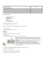
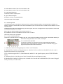
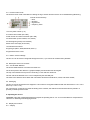
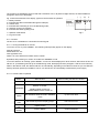
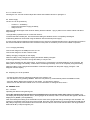
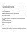
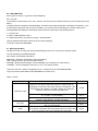
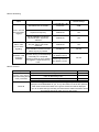
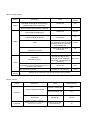
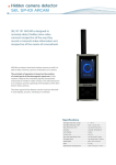
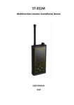
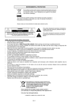
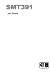
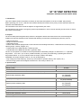
ST 107 EMF DETECTOR
TECHNICAL DESCRIPTION AND USER’S GUIDE
1. Introduction
This User’s Guide contains information necessary for the setup and operation of the ST 107 EMF (RF) Detector.
Before operating your ST 107, read this User’s Guide carefully and consult it every time you have questions about the
operation of the EMF Detector.
The information in this User’s Guide is subject to change without prior notice.
The manufacturer has a right to change the product’s specifications in such a manner that they do not worsen or reduce
the product’s functionality.
2. Purpose
The ST107 EMF (electromagnetic field) Detector is designed to detect and locate the sources of electromagnetic
radiation from devices intended for the unauthorized obtaining of information (eavesdropping devices), such as:
—radio microphones;
—telephone radio transmitters;
—radio-stethoscopes;
—hidden video cameras equipped with a radio channel for transmitting information;—radio beacons for tracking moving
objects (people, vehicles, freights, etc.);
—unauthorized use of GSM and DECT cellular phones;
—unauthorized use of Bluetooth and 802.11g (WLAN, WiFi);
The ST 107 will operate in accordance with its specifications if the battery voltage is no lower than 1.1 V. Operating
temperature: –10º to 35º C (14º to 95º F). Relative humidity: up to 95% (noncondensing). Operating the device at
temperatures below –5º C (23 F) will slow down the output of data to the display.
WARNING! The output amplifier of the ST 107 may be damaged by:
—high voltage from static electricity, which may accumulate on synthetic clothing, floor carpets, etc.);
—sources of high-power electromagnetic interference in the vicinity of the ST 107.
3. Specifications
Frequency range, MHz
50-7000
Channel 1, MHz
50-2500
channel 2, MHz (with SHF antenna )
2500-7000
Frequency range 1
-75 (50MHz)
-70 (1500MHz)
-50 (2500MHz)
Threshold Input sensitivity, dBm:
55 (50-2000MHz)
40 (2000-2500MHz)
Display dynamic range, db
Frequency meter sensitivity, dBm
-35 (500MHz)
-40 (1500MHz)
-20 (2500MHz)
Frequency measurement error,%
0.005
Low-pass filter cutoff frequency, MHz
750
Frequency range 2
Threshold Input sensitivity, W/cm2
Dynamic range, db
(2-9)* 10-10
45
Power supply, V:
internal Li pol battery
external power supply/charger
3.6V
5
Current consumption, mA
<80
Dimensions Prime Unit (without antennas), mm
Dimension SHF antenna
85x53x19
D= 16, L=72
Weight Prime Unit (without antennas), kg
0.15
4. ST 107 box content
1.ST 107 EMF Detector Unit
2. UHF antenna
3. Charge/Power supply
4. Cable USB
5. Mini-CD
6. This User’s Guide
7. SHF antenna (optional)
5. Operating principles and brief reference
The ST 107 utilizes the principles of wideband detection of electric fields.
5.1. Operating modes
The ST 007 operates in three main modes:
—Search;
—Monitoring;
—Log view.
The device has a menu that allows for its configuration.
5.1.1 Search Mode
This mode is intended for detecting sources of electromagnetic radiation.
I n this mode, the ST 107 receives radio signals, detects them, and outputs them
to the built-in display and as an audio signal to the earphones and the built-in
speaker. The level of the signal is indicated on two 32-segment level meters on
the display.
Adjacent segments (9) light up to indicate the average value of the level of the
detected signal, while a single lit up segment (7) shows its peak value.
The ST 107 can measure current frequency values of the radio signal and
determine its most stable value (for signals with a constant carrier frequency).
The ST 107 also displays the detection of GSM, DECT, Bluetooth, and 802.11g
(WLAN, WiFi) signals.
1 The number of displayed Bands /temporary indication of zero level of gauges
2 indicates the high-pass filter is on
3 32-segment meter indicating the level of Channel 1
4 32-segment meter indicating the level of Channel 2
5 current absolute value of the zero level of Band 1 dB
6 current absolute value of the zero level of Band 2 dB
5, 6 radio signal frequency
7 indicator the level of pulse power
8- type of detected signals
9 Indicator the level of integrated power
10 current range of level gauges
5.1.2. Monitoring Mode
The Monitoring mode is intended for detecting sources of electromagnetic radiation and storing data in NVRAM. The
maximum number of events that can be stored in NVRAM is 4,096. The events can be viewed when the detector is in the
Log View mode.
The Monitoring mode has an extended range of alarm signals, which can be triggered if the signal passes a certain level
or frequency threshold, or if a certain
type of signal is detected (GSM, DECT, Bluetooth, 802.11).
It is possible for the user to schedule the ST 007 to turn on and off.
This mode has two basic operations:
5.1.2.1. User controlled operation
The ST 007 is placed so that it is visible to the user. This is useful for detecting devices for the unauthorized obtaining of
information among the visitors of an office, for example.
5.1.2.2. Autonomous operation
The ST 007 is placed in an area where the use of eavesdropping devices is
suspected, and the electromagnetic environment will be monitored during a preprogrammed period without user interference.
1, 3 indicators the level of integrated power in the 1 and 2 Channels
2. 4 threshold level markers of integrated power: when the level exceeds the set threshold level, the event is
logged in the protocol (set via the menu)
5 type of detected signal: DECT, GSM. Bluetooth, and 802.11 and signal frequency in the XXXX.XX MHz
format.
6,7 indicators the level of pulse power in the first and in the second frequency range.
8,9 threshold level markers of pulse power: when the level exceeds the set threshold level, the event is logged
in the protocol (set via the menu).
5.1.3. Protocol View mode
The Protocol View mode is intended for viewing the log of events stored in the ST 107’s NVRAM during Monitoring.
Events can be sorted by:
—time;
—duration;
—signal level;
—frequency value.
1 memory bank number (1–9)
2 current event number (001–999)
3 total number of events in the bank (001–999)
4 event duration (hours:minutes, max, 99:59)
5 event beginning time (hours:minutes)
6 date of the event (day and month)
7 threshold level markers
8 signal type (DECT, GSM, Bluetooth, 802.11)
9 signal levels of the event.
5.1.4. Menu. Custom settings.
The ST 107 can be custom configured through the menu, if you choose to override factory defaults.
5.2. Description of the box contents
5.2.1. ST 007 EMF Detector
The ST 007 EMF Detector is a small form-factor box.
On the front panel of the detector: a graphical display and six-button thin film keypad.
The top of the detector has a ports for connecting a UHF and SHF antennas.
The left side of the detector has a 3.5 mm earphones jack and USB port.
The back of the detector has a sticker with information about the manufacturer, model, and serial number;
5.3. Packaging
The ST 107 and its accessories are shipped in a box made of corrugated cardboard with the dimensions of 170 x 150 x
60 mm (6.7 x 6 x 2.4 in.).
For convenience, as well as to prevent the sliding of the contents, the detector and its accessories are placed in a
specially molded styrofoam insert.
6. Operating the ST 107
WARNING! This User’s Guide describes the principles of operating the ST 107. It is not intended as a comprehensive
reference for detecting eavesdropping devices.
6.1. Display and controls
6.1.1. Display
The results of are indicated a four-line LCD with a resolution of 97 x 36 pixels as digits and text, as well as additional
pictograms at the top of the display.
Fig. 3 shows the elements of the display, typical for all the modes of operation:
1—battery level/AC;
2—indicates that data is transmitted through the USB port;
3—volume level;
4—indicates that scheduling is on for the Monitoring mode;
5—real-time clock (hours:minutes)
6—indicates that audio signaling is off;
7—operation mode status
`
Fig 3
L—Log View mode.
6.1.2. Controls
The ST 107 is controlled from a six-button thin film keypad.
6.1.2.1. Turning the detector on and off
To turn the ST 107 on press <MODE>. The following will temporarily appear on the display:
SmerSH Technics
Russia 2009 Ver. X.X
www.spymarket.com,
where X.X. is the detector’s firmware version number.
By default, after powering on, the ST 107 enters the <SEARSH> mode.
To turn the detector off manually, press <MODE>. “Power off” will be displayed for three seconds, after which the ST 107
will turn off. (If scheduling was set up for the Monitoring mode, the display will show pictogram 4 and the current time 6.)
When in the Search mode, the detector will turn off automatically, depending on the idle time value set (i.e. time after the
last key has been pressed) in the Menu. The ST 107 will not turn off automatically if used with the power supply.
6.1.2.2. Control buttons explained
Button
Main function
Text color
White
Chooses Search, Monitoring, and turns the
detector on and off.
PWR/MODE
ZERO
SENS/
EXIT
VOL+
VOL–
MENU
ENTER
SEARCH Mode->Power off>MONITORING mode->Power off
Secondary function
Used for setting the detector via Menu
Yellow
-
Sets indication threshold level in SEARCH
mode
Up one menu level
Sets sensitivity level for display gauges
Exit from the menu
Adjusts volume
Moves up and down in the menu
Enter in MENU
Confirms selection
6.1.2.3. Volume control
Pressing the Vol– and Vol+ buttons adjust the volume and indicates its level on pictogram 3.
6.2. Power supply
The ST 107 can be powered by
-
a built in Li – Pol Battery ;
external charger/power supply (included);
USB port of PC.
When the batter discharges to the minimum battery level the indicator 1 (Fig. 3) will turn from solid to outline and will be
begin blinking.
Average battery operation time of no less than 8 hours.
To extend the built-in battery life, we recommend avoiding the situation when it is completely discharged.
In Monitoring Mode we recommend using the detector with the external power supply.
It is safe for the data and settings to leave the device out of power for extended periods of time. All information is stored in
the device’s NVRAM and will not be lost if the device loses power or the battery runs out in the middle of operation.
6.2.1. Charging the Battery
Connect the charger to the USB port on the ST 107.
Connect the charger to an 220 V electric outlet.
“Battery Charging” will appear on the display.
When the battery is fully charged, the display will indicate “Battery Charged.”
It takes approximately 2.5 hours to charge the battery to 100 per cent.
If the device operates from the power supply, or whenever it is connected to a powered USB port on the computer, the
battery will be charging automatically. In this mode it will take approximately 12 hours to completely charge the battery.
When the battery is fully charged and the detector continues to operated from the power supply, pictogram 1 will
disappear from the display.
6.3. Preparing ST 107 for operation
- connect the UHF and SHF (optionally) antennas to the detector unit;
- turn the detector on by pressing «MODE». When the unit powers up, it automatically enters the SEARCH mode;
- if the text “Battery Discharged” appears on the display, you will need to charge it.
- set the time on the detector’s internal clock. For more information on setting the time, see 6.7.
6.4. SEARSH mode
6.4.1. Controls
Operating the detector using the keypad:
To set the indication threshold of the signal compared to the current level of the radio signal press ZERO once.
The display will temporarily indicate “Zero” , all the gauges will be cleared, and the current level of the signals in dB will be
displayed in 5 (BAND 1) and 6 (BAND 2).
After each subsequent setting of the threshold level, the scale of the gauges will change according to the remainder. For
example, if the absolute value of the zero level is 24 dB, the entire meter will be linear in the range between 24 dB and 56
dB (1 dB per segment); if the absolute value of the zero level is 8 dB, the entire meter will be linear in the range between
8 dB and 56 dB (1.5 dB per segment); etc.
To set the indication threshold of the signal with zeroing the values in 5 and 6 press ZERO when you see “Zero”
displayed .
Setting the sensitivity of level gauges.
Press SENS sequentially to cycle through the available sensitivity levels. The selected value will be displayed in 10:
“L”—low sensitivity level, the entire meter spans out 55 dB;
“M”—medium sensitivity level, the entire meter spans out 35 dB;
“L”—high sensitivity level, the entire meter spans out 15 dB.
6.4.2. Usage
Set the indication level threshold. You cannot set the threshold when in the room to be scanned. If eavesdropping devices
are already present and operating in the room, their radiation level will be considered the “zero” level by the detector.
When the antenna approaches a eavesdropping device, depending on the band of signal, the number of solid segments
of one of the level gauges will increase
When the signal level exceeds 32 dB, the detector will display the value of the signal’s detected frequency.
To determine the precise location of the eavesdropping device, press ZERO to set the zero level to the current signal
level and continue to scan the room. Repeat this until you locate the offending device.
Change the sensitivity of the level gauges if necessary.
To attenuate interference from powerful radio transmitters in the range up 900 MHz (base station of GSM and DECT), we
recommend engaging the low-pass filter.
6.5. MONITORING mode
To select the Monitoring mode, press Mode (see 6.1.2.2.).
“Monitor Start” will be displayed and a five-second countdown will begin. This period is intended for measuring the
background level, against which the ST 107 will compare all subsequent measurements.
6.5.1. Controls
Use Menu to adjust the settings for this mode.
In this mode, the following conditions are always true:
—the range of the level gauges is 0 to 55 dB;
—the ZERO and SENS are disabled.
6.5.2 Usage
Adjust the settings in the Menu, if necessary.
Place the ST 107 in the area where the presence of eavesdropping devices is suspected.
If the alarm conditions are met, “Alarm” will be displayed.
The ST 007 logs events of each monitoring session to a separate memory bank. The total number of memory banks is 9.
Bank #1 always contains the most recent events; bank #9 has the oldest events. When all the memory banks are full, the
events in bank #9 are deleted to make room for new events. The maximum number of events in one memory bank is 999.
The total number of events that the ST 007 can hold is 4,096.
The minimum time between two events of the same type is 1 seconds. Such events will be logged in the protocol as two
separate records. If a second event of the same type is detected within 1 seconds, the ST 107 will not log it as a separate
event. Instead, the duration of the previous even will be extended.
6.6. LOG VIEW mode
If the log has no events, “Log Empty” will be displayed.
6.6.1 Controls
To browse the events use the VOL+ VOL– buttons. The events are numbered according to the sort order (set via the
Menu).
To switch between the banks press SENS/EXIT. The bank with the latest information will always be bank №1. If you
choose sorting order other than by time in the Menu, you may also see the following text: “Sorting. Please wait...”
Pressing MENU will display the information about the cause of the event in the following format:
1— level XX dB
2—DECT, GSM, Bluetooth, 802.11
3—Captured frequency or frequency change = XXXX.XX MHz
Only the fields that indicate the cause of the event are displayed.
To exit the mode press SENS/EXIT.
6.7 Working with Menu
The Menu is used to change the factory default settings of the ST 107 to suit your particular needs.
To enter the Menu press MENU/ENTER.
Four options are available under Menu:
MONITOR - settings for the Monitor mode (see Table 2).
LOG - settings for the Log View mode (see Table 3).
SYSTEM - general system settings, such as backlight, time, language, etc. (see Table 4).
CHANNEL- choice of displayed channels (1 or 2 or 1+2) and set of Filter.
Use VOL+ and VOL– buttons to highlight a menu. To choose a menu press MENU/ENTER.
To go up one level press ZERO. Press SENS/EXIT to exit the menu.
Table 1. Search
Option
Frequency meter
Diff mode
Timer
Description
Default settings
Set level—sets level at which the frequency meter will turn on,
depending on the level of the upper meter (0 to 64 dB with 1 dB
increments): 0 dB—always on, 64 dB—always off. Having the
frequency meter off increases the battery life.
32 dB
Capture level—sets stable level of signal frequency for display (0.1
to 1 % with 0.1 % increments).
AOR model—chooses type of scanning device to transmit
frequency data (AR-800, AR-8200, AR-5000)
Averaging—sets averaging time (0.1 to 6 sec with 0.1 increments)
Scale—sets scale for level meters (20 to 100 % for the entire meter
with 10 % increments)
Switch-off time—sets time for automatic switch off of the detector
(in the Search mode) after the last keystroke (8 sec to 34 min with
8 sec increments). Only when operating from the battery.
0.5 %
AR-8000
1 sec
40 %
30 min
Table 2. Monitoring
Option
Event—sets the
event to trigger
logging
Description
Value
Default settings
Set relative level of ALARM.
1 to 64 dB with 1 dB
increments.
20dB
Capture of Frequency
Set/Not set
Set
Signal GSM,DECT,BT,WLAN
log events when signals are
detected
Set/Not set
Set
Set/Not set
Set
Set/Not set
Not set
Display only
Only the “Alarm” text will be
Alarm—sets
displayed
type of alarm
Alarm hold
signaling
Alarm indication remains onscreen
before any key is pressed.
Sets time in hours (0–23) for
automatic turning on the Monitoring
Schedule—sets
mode daily for a set period.
monitoring
Monitoring results for each sessions
schedule
are logged in a separate memory
bank.
Monitoring start time.
By default 9 hours.
Monitoring end time.
Not set
By default 17 hours.
Table 3. Protocol
Option
Description
Default settings
By time—sorts events according to the time of occurrence.
Set
By level—sorts events by signal level as displayed by the top
Sorting—sorts logged
Not set
meter in descending order.
events according to one
of the parameters
By CHANNEL—sorts events by CHANNELs
Not set
By duration—sorts events by duration in descending order.
Not set
Erases all logged events. A confirmation dialog (“Are you sure?”) will be
displayed. Press SENS/EXIT for yes, or any other button to cancel the operation.
After all the events are erased, the “Logs are erased” text will be displayed.
Erase all
If you do not erase the logs manually, the bank with the oldest information will be
automatically erased to make room for new events.
Table 4 System settings
Option
Value
Default
settings
Set/Not set
Set
Set/Not set
Set
Set/Not set
Not set
10 to 100 % with 10 %
increments
50
Sets time for automatic turning
off of backlighting after a period
of inactivity (8 sec to 2 min with
8 sec increments).
24 sec
Sets display contrast
(10 to 100 % with 10 %
increments).
50
Language
English/Russian
Russian
Date/Time
Sets date and time.
Hours (h), minutes (m),
seconds (s), day (d), and
month (M) are set separately.
Press Enter to modify the next
parameter.
Set by user
Set/Not set
Set
from –2 to +2 min with an
accuracy of 1 sec per day.
00:00
Description
Battery empty sound
Repeated sound signals accompanying
“Battery Empty” text on the screen.
Button pressed sound
Sound confirming that a button is pressed
Backlight
Sound
Turns display backlighting on
Backlight brightness
Adjusts backlight brightness
Display
Timer
Contrast
Clock
PC sync
Automatically synchronizes with the clock on a
PC during data transfer.
Correction
Sets daily clock correction
Factory
defaults
Reverts ALL the settings of the detector to their factory defaults.
Table 5 Channel
Option
Description
Value
Default settings
channel 1 Set/Not set
Set
channel 2 Set/Not set
Set
On/Off Filter
Set/Not set
Not set
Choice of a priority between
measurements of frequency and
identification of signals
From 01- to 05 with
increments of 01
03
choice of displayed channels
Channel
Freqmeter
7 Working with the Computer
Before connecting the ST 107 to the computer, install the software from the Mini CD or download the latest version from
the Internet at www.smersh.ru/manual/st107.
Connect the ST 107 to the computer with the USB cable. When prompted to install the device driver choose the
installation path. Confirm the installation by agreeing with the prompt.
7.1 “ST 107 PC DATA” Software
The software is intended to:
—display real-time data and the results of operation of the ST 107;
—load and display textual and graphical information of the operation of the ST 107 in Monitoring Mode (Event Log);
—operate the device remotely from the PC.
The complete manual on the ST 107 PC DATA software is included on the Mini CD.
7.2 Downloading firmware updates from the Internet
Navigate your web browser to http://www.spymarket.com/manual/st107.shtml
WARNING! The following steps for updating the firmware in the ST 107 are true for Microsoft Internet Explorer™. The
procedures for other web browsers may be different from those described below.
Click the appropriate firmware version. You will be presented with the following prompt: “Would you like to open the file or
save it to your computer?” Choose Open and within a few seconds the application will be downloaded and launched.
Connect the ST 107 to a free USB ports of your PC. Press PWR/MODE.
Monitor the updating process on your computer display. If this process fails, the application will offer you to attempt
updating the ST 107 again.
You can copy the downloaded updater application to any portable media and use it on another PC.
8. Some limitations and recommendations
8.1. Use the original packaging for storing and transporting the ST 107.
If you are not using the unit for a prolonged period of time, keep it in a closed, heated room with a temperature of 10 to
35ºC (50º to 95º F) and relative humidity of no more than 80 %.
When transporting the unit in the original packaging, take measures to prevent it from blows or excessive pressure.
8.2. After the unit has been exposed to temperatures below –5ºC (23º F) for prolonged periods (over 4 hours), turn it on
only after making sure there are no visible traces of condensation.
8.3. When operating the unit, try to protect it from concentrated moisture (rain, drizzle, and snow).
Prevent the LCD from prolonged exposure to direct sunlight.
9. Warranty information
9.1. The manufacturer guarantees that the ST 107 will comply with the specifications for a period of 12 months beginning
from the day of purchase.
9.2. The manufacturer will carry out repairs of the unit and its accessories or replace them if they malfunction or if the
functioning will not comply with the stated specifications free of charge during the guarantee period.
9.3. This warranty only covers free-of-charge repair or adjustment of faults that are not the result of improper use, failure
to follow the usage tips and recommendations stated in the User’s Guide, improper storage or shipment, and mechanical
damage to the unit or its parts. The warranty will only be ensured with a guarantee claim accompanied by a properly filled
out certificate of warranty.
9.4. The warranty is granted for every unit only if the purchaser provides a certificate of warranty filled out by the
manufacturer and the seller.
9.5. The manufacturer offers post-guarantee servicing of the ST 107.
SmerSH Technics grants its official dealers the right to establish additional warranty periods.
10. Quality control certificate
The ST 107 EMF detector
S/N____, has passed Q.C.
Manufacture date:____
Certificate of warranty #1
For warranty repair (servicing) of the ST 007 EFM Detector
S/N___ Manufacture date__
Manufacturer
Sold (name of the dealership or trade organization)
Date
Sales representative (signature) Seller
Certificate of warranty #1 (tear off part)
For warranty repair (servicing) of the ST 007 EFM Detector
S/N___ accepted__
service technician (name and signature)
Toggles the low-pass filter on and off in Search mode
Enters the Protocol View mode
Engaging/disengaging the low-pass filter.
To toggle the low-pass filter on and off press and hold Sens/UHF for more than two seconds. The state of the mode will
be reflected in 10.
The default state is OFF.
Choosing audio signaling type.
To choose between two types of audio signaling press Sound/Prt.
When you choose “Tone” (see 1 on the display), clicks with a frequency proportional to the level of the detected signal will
be heard through the built-in speaker and earphones. The higher the signal level the more rapid the clicks you will hear.
The audio signaling is triggered as soon as the signal level reaches the fifth segment of the meter.
If you choose “Aud,” you will hear an audio signal demodulated by the amplitude detector instead of clicks.
The default setting is “Aud.”