1
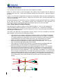
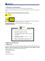
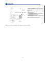
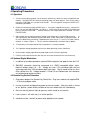
Fiber Coupled Laser Module
Operation Manual
115-80010-003 Rev. 3
Contents
1 Safety Precautions ..................................................................................................................................... 3
2 Application and Features ........................................................................................................................... 4
3 Diagrams .................................................................................................................................................... 5
4 Operating Procedures ................................................................................................................................ 7
5 Maintenance ............................................................................................................................................... 8
6 Service ....................................................................................................................................................... 8
2
1 Safety Precautions
This instruction manual explains how to use the Fiber Coupled Laser Module.
Before use, please read this manual thoroughly. After reading, keep it together with the product for
reference when necessary. Please retain packaging material in the even the unit is stored or shipped in
the future.
Caution – use of controls or adjustments or performance of procedures other than those specified herein
may result in hazardous radiation exposure. Body of the unit contains labels specifying wavelength and
maximum emitted power.
Recommend following user requirements for Class 3B products according to latest ANSI Z136.1 Standard
for the Safe Use of Lasers. Use protective eyewear when engineering or other procedural and
administrative controls are inadequate to eliminate potential exposure in excess of the MPE.
Laser Diode Optical Feedback Warning
Semi-conductor laser diodes are highly sensitive to optical feedback. They can suffer damage that
maybe immediately apparent through loss in power or a reduction in life. Furthermore, wavelength
stabilized laser diodes may lose their spectral characteristics such as center wavelength and linewidth if
sufficient optical feedback exists.
Your Ondax laser diode does not incorporate an optical isolator, so may be susceptible to extraneous
optical feedback. We recommend the following precautions:
•
•
•
•
If the output of the laser diode is collimated, all reflective surfaces in the optical path should be
angled so that surface reflections would not be reflected back to the laser diode. Furthermore,
since optimal alignment for interferometric measurement instruments is often achieved with the
instrumentation optics at normal incidence to the laser, we recommend the use of optical
isolators or slightly misaligning the instrument to avoid direct feedback into the laser.
Beware of focusing the light output on a highly reflective/scattering surface. This is another
means of generating high optical feedback to the diode.
If fiber coupling, anti-reflective (AR) coated tips are recommended for multimode (MM) fiber.
Angle polished tips and AR coating are recommended for single mode (SM) fiber.
Beware of wavelength selective filters with narrow wavelength pass bands. Care should be
taken not to align at normal incidence to the beam. Furthermore, be careful not to align the
reflected light to be normal incidence during the alignment process (e.g. sweeping the beam
back across the laser during alignment). If such a possibility is unavoidable, use a sufficient OD
filter (or isolator) at the output of the laser diode during the alignment process. Please note that if
sufficient additional feedback reaches the laser diode, it would overcome the grating-induced
stabilization, unlocking and shifting the wavelength of the laser beyond the pass band of the filter.
This will dramatically increase the reflected intensity back into the laser possibly causing
damage.
Optical Element 2
Optical Element 1
Collimating Lens
Optical Element 1
Optical Element 2
Collimating Lens
3
1.1 Explanation of Warning symbols
The meaning of the symbols used in this manual and attached to the product follows.
Warning messages are intended to prevent accidents to operating personnel such as burns and electrical
shocks.
Some caution messages are intended to prevent damage to the module.
Precaution for handling electrostatic sensitive devices.
Visible and/or invisible Class 3B laser radiation. Avoid direct exposure to
beam. Wear suitable protective eyewear whenever laser is in operation.
Warranty void if removed
Warranty void if removed. Do not open the module.
Warning
To prevent permanent damage, observe these precautions:
1. Protect against electrostatic discharge.
2. Avoid external damage to the enclosure.
3. Use supplied power supply or power supply meeting
specifications.
4. Do not drop the module or operate it at extreme
temperatures or humidity.
5. Beware of optical feedback from reflective surfaces.
Permanent damage to the laser diode is possible.
2 Application and Features
2.1 Applications
This device is a compact fiber coupled laser module for high precision equipment. It plays a pivotal role in
testing or manufacturing, and can be used in various applications such as Flow Cytometry, Confocal
Microscopy, Protein Crystallography, DNA Sequence, Semiconductor Defect Detection, Thin Film
Analysis; High Density Data Storage, and Raman Spectroscopy.
2.2 Standard Features
• Plug & Play
• ESD Protection
• Adjustable Output Power
4
• LD Current Protection
• Temperature Stabilized
• Compact Size
2.3 Optional Features
• TTL Modulation (SMA Connector)
3 Diagrams
Figure 1 – Wiring Diagram – Wire Harness
7
6
1
2
8
3
9
4
5
Pin
Function
1,2
+5 Volts DC (+/- 0.25V) Input, Max current 2.5A
3
Laser Enable
4
Temperature OK
5
Power Control
6,7
Ground
8
LD I Op (monitor)
9
PD I mon (monitor)
110/220V
Figure 2 - AC-DC Adapter (OEM ONLY)
5
DB9 Connector to module. (Cable is included)
1. Power on/off key switch—Located on the front panel of
the Remote Key Switch, this switch enables users to power
the unit on with the turn of a key. The unit is inoperable when
key is removed.
2. Emission indicator—This red LED, located to the upper
right of the front panel, lights up when the unit is on to warn of
eminent laser emission.
3. 5-second activation delay—The unit does not apply
power to the laser module until five seconds after a user has
turned the key switch to the “on” position.
4. Remote interlock & connector—This feature is located
on the rear panel of the Key Switch. The unit will not operate
without the interlock intact. Interlock needs to be shorted for
power to be available for laser diode module.
Figure 3 – Key Switch Power Adapter (Power Adapter to 110/220V included)
6
4 Operating Procedures
4.1 Operation
1. Turn on unit by applying power (see instructions below if key switch has been included with your
module). The lower LED will illuminate indicating power has been applied. The LCD will state a
message “STARTING” for a period of 30 seconds. The message will change to “LASER OFF”
immediately afterwards.
2. Enable the interlock by applying 5VDC to pin 3. If using the supplied wire harness, connect pin3
to pin 1 or 2 of the DB9 connector, see Figure 1. 10 Sec later the upper LED will illuminate and
the LCD indicate “LASER ON”. Interlock maintains laser temperature when disabled. DO NOT
EXCEED 5VDC.
3. Adjust power level by applying external analog signal voltage to pin 5 of the DB9 connector.
0
volts corresponds with maximum optical power while 5 volts corresponds to minimum power. 05V can be obtained by connecting a potentiometer across the pin 1, 5 and 7 (5V, Power Control,
Ground) as shown in Figure 1. This pin could be modulated at a maximum rate of 100kHz.
4. ~5V between pin 4 and ground indicates temperature is at normal condition
5.
Pin 8 provides voltage proportional to the laser diode operating current (10mV/mA)
6. Pin 9 provides voltage proportional to photo diode current (1V/mA) if applicable.
7. For best results allow 30 minutes after the laser has been turned on for the unit to warm-up.
4.2 Optional Digital Modulation
1. In addition to the above procedure, connect SMA receptacle side opposite from the LCD
2. SMA-BNC connector should be connected to a CMOS compatible digital signal.
Nominal voltage range is 0 – 5V. Voltage less than 1.5V considered logic low and
anything greater than 3.5V considered logic high signal. Signal should not be less than
0V or greater than 5V. Voltage between 1.5 and 3.5 are indeterminate and should be
only encountered during transitions.
4.3 Remote Key Switch Procedure
1. Plug power adapter into Remote Key Switch Box. Plug laser module into supplied DB9
– 2.1mm plug adapter cable.
2. Use key to activate and deactivate power to the laser module. After key switch is turned
to “on” position , power will be available for the laser module after a 5 second delay.
3. Emission warning light will light up upon key switch turned to “on” position.
4. Laser system is “off” when key is in vertical position.
5. Interlock must be “shorted” for power to be applied to laser module
7
5 Maintenance
5.1 Maintenance and Inspection
Routine maintenance is not required. If the unit appears to be operating incorrectly or with low output
power, check the following:
•
Inspect the enclosure for scratches, dings, dents, or other signs of damage due to falling.
•
Verify that the module enclosure has not been opened and the factory seal is intact.
•
Inspect the fiber and loose tube for twists, kinks, or a break.
•
Ensure that the operating environment is within specifications.
5.2 Operating & Storage
The operating and storage environment must be as follows:
•
Operating temperature between 10 and 40 °C.
•
Storage temperature between 0 and 50 °C.
•
Non-condensing humidity levels.
•
Electrostatic-free.
•
No violent impacts or excessive vibration.
6 Service
6.1 Repair
There are no user-serviceable parts inside and do not attempt to open housing. Warranty would not be
valid if housing has been opened. If the module fails during use, check the items in section 5.1 before
requesting an RMA.
Defective modules that are beyond the warranty period will be repaired at cost, if possible. A RMA must
be requested before sending it to us. When shipping, please use a box at least five times as large as the
module with enough packaging material to prevent any movement of the module within the box.
6.2 For Information or Enquiries
If you need information regarding purchase or repair, or for any other Sales related questions, please
contact the dealer or selling agent from which the module was purchased.
6.3 Contacting Ondax
Ondax, Inc.
850 E. Duarte Rd.
Monrovia, CA 91016
Tel: 626-357-9600
Fax: 626-357-9321
Web: http://www.ondax.com
Email: [email protected]
8