1
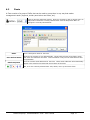
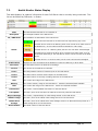
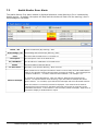
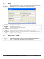
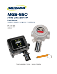
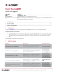
VIGIL VCM – DVR Central
Management v6.00.0000
User’s Guide
January 2011 Revision
Table of Contents
1 INTRODUCTION ......................................................................................................................................................... 3 2 SYSTEM REQUIREMENTS ........................................................................................................................................ 4 3 FEATURES ................................................................................................................................................................. 5 4 VCM CLIENT LOGIN .................................................................................................................................................. 6 5 VCM CLIENT MAIN WINDOW.................................................................................................................................... 7 6 ADD / EDIT DVR SERVERS ..................................................................................................................................... 10 6.1 6.2 6.3 7 MANAGE HEALTH SETTINGS .................................................................................................................................. 11 SEARCHING DVR SERVERS .................................................................................................................................. 16 FLEETS ................................................................................................................................................................ 17 HEALTH MONITOR .................................................................................................................................................. 18 7.1 7.2 7.3 7.4 8 HEALTH MONITOR TOOLBAR ................................................................................................................................. 18 HEALTH MONITOR STATUS DISPLAY ...................................................................................................................... 19 HEALTH MONITOR ERROR ALERTS ........................................................................................................................ 20 DVR DETAILS....................................................................................................................................................... 21 ACCESS CONTROL ................................................................................................................................................. 23 8.1 8.2 8.3 9 GROUPS .............................................................................................................................................................. 23 USERS ................................................................................................................................................................. 24 SEARCH USERS / GROUPS .................................................................................................................................... 24 UPDATES.................................................................................................................................................................. 25 10 JOBS ..................................................................................................................................................................... 27 10.1 10.2 11 JOBS TOOLBAR ................................................................................................................................................. 27 JOBS STATUS DISPLAY ...................................................................................................................................... 27 SETTINGS ............................................................................................................................................................. 28 11.1 11.2 11.3 11.4 11.5 11.6 11.7 11.8 GENERAL SETTINGS TAB ................................................................................................................................... 28 LOGIN SETTINGS TAB ........................................................................................................................................ 28 HEALTH MONITOR TAB ...................................................................................................................................... 28 EMAIL SETTINGS TAB ........................................................................................................................................ 29 MATRIX CONTROLLER TAB ................................................................................................................................ 29 JOBS TAB ......................................................................................................................................................... 29 ALERTS TAB ..................................................................................................................................................... 30 ANALYTICS TAB................................................................................................................................................. 30 12 LANGUAGE SWITCHER ...................................................................................................................................... 31 13 CONTACT INFORMATION ................................................................................................................................... 32 «PossvCompany» «SoftwareName» VCM - User’s Guide
Page 2
1 Introduction
This guide describes the installation and operation of 3xLOGIC’s VI GIL VCM so ftware. This version of
the User’s Guide is current to Version 6.00.0000 of the VIGIL VCM software.
VIGIL VCM provides a simple, yet effective way to monitor and manage multiple VIGIL Server DVRs. It
can poll ea ch DVR’s health remotely and independently for information such as cameras on line,
recording status, disk s torage and many other points of interest and alerts. VIGIL VCM organizes your
DVRs into concise lists, called fleets, for ease of management. In addi tion to these features, VCM
provides a way to centrally manage software update profiles for each remote site.
3xLOGIC (www.3xlogic.com) produces enterprise class DVRs and state-of-the-art surveillance software.
VCM Server and Client Overview
«PossvCompany» «SoftwareName» VCM - User’s Guide
Page 3
2 System Requirements
PC Feature
Operating
System
Recommended
Microsoft Windows XP Professional SP3 or Windows 7 Professional or Ultimate (32 or 64 bit)
CPU
Intel Core2 Duo, minimum 2.0 GHz
RAM
Minimum 2 GB
HDD
SATA (Minimum 50MB required for install)
Database
Microsoft SQL Desktop Engine
«PossvCompany» «SoftwareName» VCM - User’s Guide
Page 4
3 Features
Feature
Details
Health Monitor
Provide ‘at a glance’ status of al l DVR Servers fo r configured options. Al so provides
popup and / or email alerts when configured alarm conditions are met.
Access Control
VIGIL Server Access Control functions on a workgroup model , each DVR mai ntains its
own Access Control List. VCM Server can Push User and Grou p information to Si ngle
and Multiple DVRs.
Updates
Configure update profiles for Si ngle DVR or Groups of DV R’s to have di fferent update
schedules and options.
Centralized Analytics
Database
Copies the Anal ytics Data from Configured DVR’s to a Centrali zed Database to simplify
Analytics Reporting.
Note: The Target Central SQL Database requires Central Video Analytics Setup Scripts
to be run on the system.
«PossvCompany» «SoftwareName» VCM - User’s Guide
Page 5
4 VCM Client Login
When the VCM Client is launched, the Login window will display. This window is used t o connect to the
VCM service.
Server
User Name /
Password
Automatically log
on as this user on
startup
The IP address or DNS name of the System running the VCM Server Service. If the Server
Service is installed on the same system as the VCM Client, use the IP address “localhost”.
The Username and Password to login to the VCM Client.
Note: The default user name and password for the VCM Service is ‘user’ and ‘123’.
When enabled, this feature will automatically log on as the speci fied user when VCM Client
is launched.
Note: It is recommended to restart VIGIL VCM Server and Client monthly.
Note: VCM Client uses Port 10507 to connect to the VCM Server Service.
«PossvCompany» «SoftwareName» VCM - User’s Guide
Page 6
5 VCM Client Main Window
This is the main view of VIGIL VCM Client. The Health Monitor will be open by default.
Icon Toolbar:
This table is a quick listing of the main toolbar buttons and their usage. Detail of each corresponding
window is outlined in later sections.
Exits the VIGIL VCM Client program. An exit confirmation window will appear.
Add a DVR to the currently selected Fleet. By default all DVRs are added to the (default)
Fleet. Clicking the
button will open a context menu for the currently selected DVR.
Opens the DVRs Window. Allows the DVRs list to be filtered for easier maintenance.
Opens the Access Control window. Users and Groups can be configured for DVRs.
Opens the Health Monitor window. This allows the user to monitor DVR Server Status.
Opens the Updates window. Update configuration can be configured for DVRs.
Opens the Jobs window. This lists tasks that still need to be completed. This allows for
unresponsive DVRs to still have the changes applied when the DVR becomes responsive.
Opens the Settings window. This is the main configuration page for VIGIL VCM.
Requests the latest DVR information from the VCM Server Service.
«PossvCompany» «SoftwareName» VCM - User’s Guide
Page 7
Status Bar:
The Status Bar is located at the bottom of the VIGIL VCM Client Window.
The date and time of the last refresh.
Shows Health Monitor Status. Click to open the Health Monitor window and the Error Alerts
window.
Displays the status of the connection to the matrix controller (if attached).
Shows Jobs status. Click to open the Jobs window.
Displays the VIGIL VCM Server that the VCM Client is currently connected to.
Displays the currently logged in user. Click to log off.
Displays the current date. Click to open the Windows Date and Time Properties control.
Displays the current time. Click to open the Windows Date and Time Properties control.
Auto Detect DVR Servers
On the File menu item, select Auto Detect DVR Servers. Find all DVR Servers on the same network that
have the option Allow Auto Detect enabled.
Start / Stop
Looking
Number of DVRs
Found
New DVRs
Add
Click Start Looking to search for DVRs, and then click Stop Looking once all DVR’s have
appeared in the list.
The number of DVR Servers detected.
The number of DVR Servers detected that are not already configured in VIGIL VCM Server.
Select the DVR Servers in the list to be added to VCM Server and click Add. If multiple
servers are selected, settings can be configured for all DVRs.
Audit Log
Monitor activities in VCM vi a the Audit Log, which is loca ted under the View menu bar it em. Specific
activities performed by VCM will be listed here along with their corresponding date/times and DVRs.
«PossvCompany» «SoftwareName» VCM - User’s Guide
Page 8
DVR Menu
The DVR menu is a context sensitive list of options, these options can be accessed from the DVR
Toolbar menu, or by right clicking on a DVR Server.
Health Monitor DVR Menu Items
Add DVR
Open the Add DVR window. This option is the only option available when no DVR
Selected in Health Monitor.
Edit DVR
Open the Edit DVR window for the selected DVR Server.
Delete DVR
Take Snapshot of
DVR Settings
Apply Settings
Snapshot to this DVR
Poll DVR
Extract Still Images
Open Still Image
Destination
Delete the selected DVR Server.
Create a backup of the DVR Server settings.
Restore the last Settings Snapshot to the selected DVR Server. The date and time of
the available snapshot is displayed on the menu.
Refresh the current status of the selected DVR Server.
Copy a still image of each camera enabled on the DVR Server and stores them in:
C:\Program Files\VIGIL\VCM\ServerIP.port
Open the Still Image folder for the selected DVR Server.
Access Control DVR Menu Items
Include all of the Health Monitor items as well as:
Update All Users
Update All Users on
All DVRs
Update all Users on the Selected DVR Server.
Update all Users on all DVR Servers.
Updates DVR Menu Items
Include all of the Health Monitor items as well as:
Send Update Profile
to this DVR
Send the Update Profile to the selected DVR Server.
Send All Update
Profiles to All DVRs
Send all Update Profiles to all DVR Servers.
Send Update Profile
to this DVR and Apply
Immediately
Send All Update
Profiles to All DVRs
and Apply
Immediately
Send the Update Profile to the selected DVR Server and Immediately Apply any
associated updates.
Send all Update Profiles to all DVR Servers and Immediately Apply any associated
updates.
«PossvCompany» «SoftwareName» VCM - User’s Guide
Page 9
6 Add / Edit DVR Servers
button for context sensitive options
Opens the Add DVR window. Use the
depending on the currently selected window, this menu can also be accessed from
the Main Toolbar DVR menu and from right clicking on a DVR.
Fleet
Name
IP Address
DVR Type
Port
Dialup Entry
Save Still Image
If Fleets have been configured, select which Fleet the DVR will be a member of. If no
Fleets have been configured, this option will not be available and all DVRs will be members
of the (Default) Fleet.
A Descriptive Name for the DVR Server.
The IP Address or DNS Name of the DVR Server.
Select either VIGIL DVR or Sanyo DSR.
The Data port for the DVR Server.
If the DVR Server is across a Dialup connection, select which Dialup connection to use.
When enabled, Copy a still image of each camera enabled on the DVR Server and stores
them in: C:\Program Files\VIGIL\VCM\ServerIP.port
Manage Access
Control
Enable Access Control management. When this option is enabled, the DVR Servers Access
Control Database will be synchronized with the VCM Server. All existing User and Group
settings will be overwritten.
Manage Health
Enable Health Monitor polling. Click the Settings... button to configure the Health Monitor
Settings.
Manage Updates
Enable Update Configuration management. When this option is enabled, the DVR Servers
Update Service settings will be synchronized with the VCM Server. All existing Update
Service settings will be overwritten.
Manage Analytics
Enable the copy of Video Analytics data from the DVR Server to the Central Analytics
Database configured in the VCM Server Settings.
Analytics SQL Port
Number
The Port number of the Analytics Database. The default port is 1433.
Groups
Save as Default
Select which groups will be pushed to the DVR Server.
Enable Save as Default to save the current configuration as the default for future DVR
Servers.
«PossvCompany» «SoftwareName» VCM - User’s Guide
Page 10
6.1
Manage Health Settings
When adding a DVR and choose to Manage Health, click the Settings button to open the configuration
window where you can configure the Health Monitor settings, Email Notification settings and configure
Failover.
Site Configuration Tab
The type of DVR, what settings are monitored and the site contact information is configured on this tab.
General Settings
DVR Type
Model
Redundant DVR
Update Frequency
Select either VIGIL DVR or Sanyo DSR. When configuring a Sanyo DSR, many options will
de disabled as they cannot be monitored or are irrelevant.
Select the Model Number of the Sanyo DSR. Disabled when configuring a VIGIL DVR.
A Redundant DVR is used for backup recording in the event that another DVR Fails.
Addition hardware is required for a Redundant DVR to function.
Set how often the VCM Server will poll the DVR for new information.
Monitored Values
Monitor Active
Cameras
Monitor Recording
Cameras
Monitor the number of cameras connected to the DVR Server. Active Cameras is the
number of Cameras expected to be connected to the DVR Server.
Monitor the number of cameras configured for recording on the DVR Server. Recording
Cameras is the number of Cameras expected to be recording on the DVR Server.
Monitor Days of
Storage
Monitor the number of days of stored footage available on the DVR Server. Health Monitor
will not generate warnings for days of footage until the specified number of days has
elapsed since the DVR began recording.
Monitor Newest
Footage
Monitor for new video footage recorded within the specified number of hours.
Monitor Newest
POS Data
Monitor for new POS Data recorded within the specified number of hours.
Monitor Newest
Audio Footage
Monitor for new Audio recorded within the specified number of hours.
«PossvCompany» «SoftwareName» VCM - User’s Guide
Page 11
Monitor Newest
V-POS Data
Monitor
Acknowledgeable
Errors
Monitor DVR
Version
Monitor for new V-POS Data recorded within the specified number of hours.
Monitor for Acknowledgeable Errors on the DVR Server.
Monitor the Version of the DVR Server.
Threshold Values
Timeouts Before
Failure
Connection
Timeout
Stalled thread
error threshold
CPU Critical
Threshold
Hard drive
Temperature
Threshold
The number of timeouts before considering a connection to be in error.
The time in seconds before a timeout occurs between the DVR Server and VCM Server.
Monitor the state of video capture threads on the DVR Server. If a stalled thread is detected
for the specified number of connection attempts an error is generated.
The maximum CPU usage allowed on the DVR Server before an error is generated.
The maximum temperature in Celsius that the DVR Server hard Drives can reach before an
error is generated.
Site Contact Info
This information is included in email notifications sent from the VCM Server regarding this DVR Server.
«PossvCompany» «SoftwareName» VCM - User’s Guide
Page 12
Email Notification Tab
Email addresses and what alerts / errors will trigger an email notification are triggered on this tab.
Notification by
Email
Auto-CC Site
Contact
Enable Email notification.
When enabled include the Site contact on all Email notifications.
Email Recipients
Email List...
Opens the Email List window where email addresses can be added or removed from the Email
Recipients for the DVR Server. This list is global for all DVRs configured in the same Fleet, if only the
(default) fleet is used, this list will be global for all DVR Servers configured.
Add / Edit
Delete
Select All / None
Email
Address
The email address for this recipient.
Name
A descriptive name for this recipient.
Scheduled
Email Alerts
Select the checkbox to enable
selective times for email alerts to be
sent to this email address.
Delete the selected email address. When an email address that exists in a Fleet’s Email
Recipients list is deleted from the Email List window, it will be deleted entirely from all fleet
and server email lists.
Select all or none of the email addresses in the list.
Custom Alert Command
When enabled, allows an alternative means of notification to be used. Enter a command or application
in the first box and parameters for it in the second box. This does not support any commands or
applications that utilize a GUI.
«PossvCompany» «SoftwareName» VCM - User’s Guide
Page 13
Notification Settings
An email will be sent to each recipient in the list and/or the custom alert will be executed when any of
the enabled criteria are satisfied. Not all criteria may be available depending on the monitored
information in the Site Configuration tab.
Email alert if no
DVR response after
Email alert if
camera number
changed after
Email alert if CPU
above critical
threshold after
Alert if data drives
are offline
Alert if recording
on backup drives
Alert if not
recording expected
days of storage
The number of failed connection attempts before an alert will be emailed.
The number of consecutive connections reporting an incorrect number of active or
recording cameras before an alert will be emailed.
The number of consecutive connections reporting a critical CPU usage level before an alert
will be emailed.
Send an email notification if a data drive goes offline.
Send an email notification if the DVR begins recording to a backup drive. Also enables
alerts for offline or offsite backup destinations.
Send an email notification if the DVR is not meeting the expected days of storage.
Alert if no footage
in past 24 hour(s)
Send an email notification if no footage has been recorded in the past 24 hours.
Alert if there are
Acknowledgeable
Errors on the DVR
Send an email notification if there are acknowledgeable errors on the DVR Server.
Alert if matrix
failover triggered
Send an email notification if a matrix failover event occurred and completed successfully.
Alert if matrix
failover failed
Send an email notification if a matrix failover event occurred and failed to complete.
Alert if DVR
version out of sync
Send an email notification if the DVR Server version does not match the version specified in
the Monitored Values section of the Site Configuration tab.
Alert if Hard Drive
temperature has
failed
Send an email notification if a Hard Drive on the DVR Server has reached the temperature
threshold specified in the Threshold Values section of the Site Configuration tab.
«PossvCompany» «SoftwareName» VCM - User’s Guide
Page 14
Failover Setup Tab
Failover is a backup operation that automatically switches video outputs to a Redundant DVR for
recording should the primary system fail. Additional hardware is required for this feature to function.
When the failover is executed, VCM Server executes a command on the Matrix Controller that will
switch the specified logical matrix inputs to the specified monitor outputs and then sets the Redundant
DVR Servers recording state to on.
Failover Enabled
Test Failover
Check to enable the failover feature for the system.
Executes a failover for 30 seconds and then resumes normal recording.
Failover Settings
Execute After
Set the number of consecutive failures before executing the Failover.
DVR Input #
The DVR input number on the Redundant DVR that will be recording the video footage from
the Matrix Output.
Logical Matrix
Input
The input number on the Matrix Controller that connects to the Primary DVR Server.
Matrix Output
The output number on the Matrix Controller that connects to the Redundant DVR.
Record Default
If the Redundant DVR is normally recording another input, the Record Default is set to on.
While the DVR is in failover, these normal inputs will not be recorded until the Primary DVR
Server comes back online.
Failover DVR
Use the DVR tab to setup the Failover DVR configuration information. DVR Type (VIGIL or Sanyo), IP or
DNS name, Username, Password and Data Port.
«PossvCompany» «SoftwareName» VCM - User’s Guide
Page 15
6.2
Searching DVR Servers
Opens the DVRs window which allows for quick identification of DVR Servers.
Using the Filters section the listing of DVRs can be shortened based on the selected criteria.
When enabled, the Edit and Delete buttons as well as the right click context menu will be
enabled for the DVR Server. If multiple DVR Servers are checked, these will apply to all
checked DVR Servers.
Add
Opens the Add DVR window.
Edit
Opens the Edit DVR window for the selected DVR(s).
Delete
Deletes the selected DVR(s) from the VCM Server.
Select All / None
Select or Deselect all currently listed DVR Servers.
Export
Print
Export the current DVR list to an HTML, CSV or Tab separated file.
Print the current DVR list to the default printer.
«PossvCompany» «SoftwareName» VCM - User’s Guide
Page 16
6.3
Fleets
A Fleet consists of a group of DVRs that can be used to group them in any way that makes
management easier (regional, similar permissions and users, etc).
Click to open the Add Fleet window. Click the
button to open a context menu to
Add, Edit or Delete the currently selected fleet. Use the Drop Down Menu to
change the currently selected fleet.
Name
Enter a descriptive name for the Fleet.
User-Defined Fields
Allows for the creation of user defined fields. These fields will need to be filled in when
new users are created for the Fleet. This information is only used as meta data for ease
of organization.
Email Recipients
Enter the contact email addresses for the Fleet. These email addresses will automatically
appear in the email list for DVRs that are members of the Fleet.
Add, or for the currently selected item: edit, delete, move up and move down.
«PossvCompany» «SoftwareName» VCM - User’s Guide
Page 17
7 Health Monitor
The Health Monitor window provides ‘at a glance’ status of all DVR Servers for configured options. Also provides
popup and / or email alerts when configured alarm conditions are met.
7.1
Health Monitor Toolbar
Toggles the Health Monitor display between displaying DVRs for the currently selected fleet
and all DVRs. This button is only visible if multiple fleets exist.
Open the Health Monitor Error Alert window. This window displays currently active and
acknowledged error alerts.
Toggles email notification for Error events On or Off. When toggle notifications off, a prompt
will appear to confirm and then the Suppress Email Notification window is opened.
Select how long the suppression of email notifications will
last. To make the term indefinite, check Never Expires.
Toggles the DVR Log side window. This window contains the Event Log for the selected DVR
Server.
Toggles the DVR Details side window for the selected DVR Server.
Print DVR Site Information for the currently selected view. Click the
button to print DVR
Details for the currently selected DVR Server. Note: DVR Details is only available when the
DVR Details side window is open.
Export DVR Site Information for the currently selected view. Can be exported as HTML, Text
File or as a Comma Separated File.
Display the number of DVR Servers with no errors in the currently selected Fleet.
Display the number of DVR Servers in Warning state in the currently selected Fleet.
Display the number of DVR Servers in Error state in the currently selected Fleet.
Display the total number of DVR Servers in the currently selected Fleet.
«PossvCompany» «SoftwareName» VCM - User’s Guide
Page 18
7.2
Health Monitor Status Display
This table displays ‘at a glance’ information for each DVR Server that is currently being monitored. This
list can be filtered by Fleet and / or Status.
Fleet
Description
IP / DNS Name
The Fleet that the DVR Server is a member of.
The Descriptive Name of the DVR Server.
The IP Address or DNS Name of the DVR Server.
Shows when the DVR Server is Online and not experiencing any errors.
The DVR Server will show as Warning when a non critical error state exists on
the DVR Server, such as Camera Number Mismatch or CPU Usage.
Status
The DVR Server is in a Warning state, but the error has been acknowledged.
The DVR Server will show as Error when a critical error state exists, such as
No Cameras Recording or the VCM Server Service cannot connect to the DVR
Server.
The DVR Server is in an Error state, but the error has been acknowledged.
In Alert Since
Site Name
Version
Displays the Time and Date that the DVR Server entered a Warning or Error State.
The Site Name listed in the DVR Server Settings.
The Version of the DVR Server software.
Cam-T
The total possible number of camera inputs on the DVR Server.
Cam-A
The total number of active camera inputs on the DVR Server.
Cam-R
The total number of currently recording cameras on the DVR Server.
CPU
Memory
Disk
The current CPU usage on the DVR Server.
The current memory usage on the DVR Server. Listed as committed/total available.
The current disk usage on the DVR Server. Listed as used/total available.
Connections
The current / total available connections on the DVR Server.
Last Update
The Date / Time of the last time the VCM Server Service polled the DVR Server.
Days of Storage
The current / expected days of video footage stored on the DVR Server.
Oldest Footage
The Date / Time of the oldest video footage stored on the DVR Server.
Oldest Alarm
Footage
Serial Number
The Date / Time of the oldest Alarm video footage stored in an Alarm Reserved portion of a
video storage drive on the DVR Server.
The Serial number of the DVR Server.
«PossvCompany» «SoftwareName» VCM - User’s Guide
Page 19
7.3
Health Monitor Error Alerts
The Health Monitor Error Alerts window is displayed whenever a new Warning or Error is detected by
Health monitor. By default, the system will beep and the window will flash until the warning / alert is
acknowledged or corrected.
Delete / All
Acknowledge / All
Fleet
Description
IP / DNS Name
Status
In Alert Since
Delete the Selected (All) Warning / Alert.
Acknowledge the Selected (All) Warning / Alert.
The Fleet that the DVR Server is a member of.
The Descriptive name of the DVR Server.
The IP Address or DNS Name of the DVR Server.
The Error Status of the DVR Server.
The Date / Time that the Warning / Alert occurred.
When a DVR Server configured for Failover enters an Error state, the DVR Health Monitor
waits for the specified number failures before executing the Failover. This is displayed as:
<number of failures> / <number of failures before Failover>, for example: 2/3.
Failover Attempts
To execute an immediate failover, right click Failover Attempts and select Execute
Failover. To stop the Failover from occurring, right click Failover Attempts and select
Ignore Failover. To re-enable, right click Failover attempts and select Re-Enable Failover.
When the Failover is successful, Executed is displayed. This means that the Failover
command has been executed on the Matrix Controller and turned on recording on the
Redundant DVR Server. If the Failover is not successful, Failed will display. Right click on
Executed to display a detailed Failover report.
«PossvCompany» «SoftwareName» VCM - User’s Guide
Page 20
7.4
DVR Details
The DVR Details sidebar contains general information about the selected DVR Server.
Refresh
Click Refresh to force an update of the DVR
Details Log.
Current Site
The Descriptive name of the Selected DVR
Server.
Reboot DVR
Click this button to Reboot the Selected DVR
Server.
DVR Details Report
Last Updated
IP / DNS Name
Description
The last time the VCM Server Service refreshed this DVR Servers status.
The IP Address or DNS Name of the DVR Server.
The Descriptive name of the DVR Server.
DVR Type
The type of DVR Server, either VIGIL DVR or Sanyo DVR.
Site Name
The Site Name listed in the DVR Server Settings.
Version
Up Since
Recorder Type
Recording Format
The Version of the DVR Server software.
The Date / Time the DVR Server started running.
The DVR Server Recorder type. Shows the type of capture card installed in the DVR Server.
Displays NVR when no capture card is installed in the DVR Server.
The video recording format being recorded, NTSC or PAL.
Oldest Footage
The Date / Time of the oldest video footage stored on the DVR Server.
Days of Footage
Storage
The current / expected days of video footage stored on the DVR Server.
Newest Footage
The Date / Time of the newest video footage stored on the DVR Server.
Connected Users
The current / total available connections on the DVR Server.
Serial Number
The Serial number of the DVR Server.
«PossvCompany» «SoftwareName» VCM - User’s Guide
Page 21
CPU Usage
Memory Usage
The current CPU usage on the DVR Server.
The current memory usage on the DVR Server. Listed as committed/total available.
Hard Drives
The number of Hard Drives in the DVR Server. Click the + to display details for each Hard
Drive, Temperature, Model, Serial number and Firmware version.
Disk Usage
The total Disk Space configured on the DVR Server. Listed as Current Used / Total. Click
the + to display details for each partition: Drive Letter\Path, % used, Free Space / Total.
Offsite Backup
Destination
If an Offsite Backup destination is configured on the DVR Server, the destination path and
amount of space remaining is listed.
The total number of Registered camera inputs on the DVR Server. Click + to display the
number of Active and Recording Cameras. For each camera input, the following information
is listed:
Type
Enabled
Active
Cameras
Recording
The type of camera connected. Analog or Network.
If recording is currently enabled.
If the camera input is currently receiving a signal.
If the camera is currently recording.
Recording Mode
The recording mode for the camera input: motion, constant, alarm,
schedule.
Recording Speed
The FPS currently being recorded.
Compression
Resolution
The compression settings for the camera input. Displays as N/A for
network camera types.
The resolution of the camera input.
Hard Drive
Corrupt
For Sanyo DVRs. Indicates a Hard Drive Error.
Video Loss
For Sanyo DVRs. Indicates a Signal Loss Issue.
Disk Full
For Sanyo DVRs. Indicates the Hard Drive is Full.
Fan Error
For Sanyo DVRs. Indicates a Fan Error.
«PossvCompany» «SoftwareName» VCM - User’s Guide
Page 22
8 Access Control
Users and Groups for VIGIL DVR Server are managed on each individual DVR Server. VCM Server
allows the Users and Groups to be configured on the VCM Server system and then pushed out to the
DVR Server system. This can be done for single DVR Servers or multiple DVR Servers grouped together
in Fleets.
8.1
Groups
button to edit or delete the currently selected
Opens the Add Group window. Click the
group. In VIGIL DVR Server, permissions are applied to Groups. Users gain permissions by
being members of groups.
Name
A descriptive name for the group.
DVRs
The DVR Servers in the currently selected Fleet that have Manage Access Control enabled.
Check the box to select which DVR Servers this group will be applied to.
Permissions
Select which permissions will be applied to this group.
«PossvCompany» «SoftwareName» VCM - User’s Guide
Page 23
8.2
Users
Opens the Add User window. Click the
button to edit or delete the currently selected user.
In VIGIL DVR Server, users gain permissions by being members of groups.
User Name
The login name for the new user.
The password for the new user.
Password
Toggle this button to hide / view the password.
First / Last Name
Select the group that the user will be a member of from the drop down list.
Group
User-Defined
Fields
8.3
The new users Full Name
These fields are configured in the Add / Edit Fleet window. This information is only used as
meta data for ease of organization.
Search Users / Groups
Opens the Search Users window. Users can be searched based on any combination of criteria
from the Add Users window. Search results can also be printed to the default windows
printer, or exported to HTML, Tab Separated or Comma Separated files.
«PossvCompany» «SoftwareName» VCM - User’s Guide
Page 24
9 Updates
The VIGIL Update Service runs on each individual DVR Server. VCM Server allows the Update Profile to
be configured on the VCM Server system and then pushed out to the DVR Server system. This can be
done for single DVR Servers or multiple DVR Servers grouped together in Fleets.
Opens the Add Update Profile window. Click the
currently selected Update Profile.
Name
button to edit, delete or send the
A descriptive name for the Update Profile.
DVR
Products to
Update
Select which products will be updated.
DVRs
Select which DVR Servers the update
profile will be applied to.
DVR Update Frequency
Configure how often to connect to the Update Servers to check for update files and whether or not to
automatically apply the update files received.
Automatically
Apply Updates
Daily
Weekly
When a new version of software is available for one of the products listed in the Local
Products to Update section, it is automatically applied. Note: When this feature is enabled,
the system will restart itself, apply the update, and restart itself again.
The Update Service connects to the Update Server once per day during the hour specified
In This Hour.
The Update Service connects to the Update Server once per week on the day selected from
the drop-down menu during the hour specified In This Hour.
«PossvCompany» «SoftwareName» VCM - User’s Guide
Page 25
DVR Update Roll
Primary Server
A Primary Server provides update files to other systems, but does not receive update files
from other systems and does not automatically apply updates locally. Update files must be
manually added to the Updates tab.
Secondary Server
A Secondary Server acts as both a client and a server. As a client it receives update files
from other Update Servers and applies them locally. As a Server, it provides update files to
other systems, both files added manually as well as files it receives from other systems.
Client
A Client receives and applies updates to local software, but does not provide update files to
other systems.
Update Server Location
Update Server
Address / Port
The DNS name or IP Address and port for the main server the update service will check for
update files.
Backup Server
Address / Port
The DNS name or IP Address and port of the backup server to check for update files. The
backup server will be checked if the connection to the main update server fails.
Network Settings
Opens the network Settings window, where you can limit bandwidth used for sending and receiving
data, Suppress network activity between speci fic times of day, and set how of ten to Pol l the Update
Server.
«PossvCompany» «SoftwareName» VCM - User’s Guide
Page 26
10 Jobs
The Jobs window displays a listing of Access Control and Update Profile jobs that have not yet been
applied to the target DVR Servers or have failed to apply to the target DVR Server.
10.1
Jobs Toolbar
Toggle the All Fleets button to display Jobs for All Fleets or just the currently selected Fleet.
Restart a Job that has reached 0 attempts remaining.
Delete the currently selected Job.
If the currently selected job is in Error, Acknowledge the error. This stops alerts from
being sent, it does not stop the job.
Acknowledge Errors for all currently listed Jobs.
10.2
Jobs Status Display
Fleet
The Fleet that the DVR Server is a member of.
Job #
The unique identifier for the Job.
Description
DVR
Acknowledged
The type of Job.
The DVR Server that the Job is being applied to.
If the job has failed to be applied, shows if it has been acknowledged or not.
Attempts
Remaining
The number of attempts remaining before the job will become inactive.
Total Attempts
The maximum number of attempts before the job will become inactive.
Created
The Date / Time the Job was created on.
Last Run
The Date / Time of the last time the Job was run.
Next Scheduled Run
The Date / Time of the next time the Job will be run.
«PossvCompany» «SoftwareName» VCM - User’s Guide
Page 27
11 Settings
11.1
General Settings Tab
Disk Flush Enabled
11.2
When enabled, the VCM Server Service saves the DVR List, Fleets and Jobs List at the set
Interval. This protects against data loss if the VCM Server Service goes offline.
Login Settings Tab
Configure the user accounts to log on to VCM Client. The default administrative user for VCM Client is:
U:user P:123
Add a New User or Edit / Delete the currently selected user.
User Name
Password / Confirm
The login name for the new user.
The password for the new user.
Select the User Group this new user account will belong to.
Administrator
Group
User
View Only
11.3
Full access to VCM Client and VCM Server Service Settings.
Full access to VCM Client, no access to the VCM Server Service
Settings.
Able to view VCM Client, unable to make any changes.
Health Monitor Tab
Select which columns will display in the Health Monitor Status Display.
«PossvCompany» «SoftwareName» VCM - User’s Guide
Page 28
11.4
Email Settings Tab
Configure how VCM Client will send outgoing Email messages for Alerts.
Mail Server
The IP address or DNS name of the Mail Server.
Port Number
The port number on the Mail Server. The default
mail port is 25.
The Name and Email Address displayed in the
outgoing emails.
From
Include VCM
IP Address
Check to include the IP address of the VCM Server in
the From line of emails from the VCM Server.
Requires
Authentication
If the Mail Server requires authentication, check this
box.
User Name /
Password
Test Email
11.5
The User Name and Password for the Mail Server
authentication.
Send a test email to ensure settings are entered
correctly. A window will prompt for an email address
to send the test message to.
Matrix Controller Tab
An attached Matrix Controller is configured on this tab. A Matrix Controller is required for Failover.
11.6
Matrix
Controller
Select the Type of Matrix Controller from the Drop
Down List.
PIN Code
The PIN Code required to logon to the Matrix Controller.
This is configured on the Matrix Controller; refer to your
matrix Controller user manual for more information.
COM Port
Settings
The COM Port settings for the Matrix Controller. These
are configured on the Matrix Controller; refer to your
matrix Controller user manual for more information.
Jobs Tab
Default # of
Attempts
The maximum number of times a job will be attempted.
Default Retry
Interval
The time in minutes between Retry Attempts.
Global Auto
Retry
Enabled
When enabled, all pending Jobs will be retried
automatically at a set interval.
Global Auto
Retry
Interval
The time in hours between Global Retry Attempts.
«PossvCompany» «SoftwareName» VCM - User’s Guide
Page 29
11.7
Alerts Tab
Audio Notification
Automatically Show
Exception Form
11.8
Enable system beep for all alerts. The audio notification will continue until the alert
has been acknowledged or fixed.
Automatically display the Health Monitor Alert Window when a DVR Server is in
Warning or Error state.
Analytics Tab
Configure the Central Analytics Server information that will be used by all DVR Servers with Manage
Analytics Enabled. The Central Analytics Server requires a Microsoft SQL Desktop Engine and Central
Analytics Database Scripts to be run.
Statistics
Alarms
Enable Statistics to send all Video Analytics Rule results to the Central Analytics
Server.
Enable Alarms to send all Video Analytics Alarm data to the Central Analytics Server.
Central Analytics
Server
The IP Address or DNS Name of the Central Analytics Server.
SQL Port Number
The SQL Port number. The default port number is 1433.
Analytics User Name
Analytics User
Password
Data Update Interval
The SQL User Name on the Central Analytics Server.
The SQL Password on the Central Analytics Server.
Set the interval in minutes that Analytics Information will be copied from the DVR
Server to the Central Analytics Server.
Test Connection
Test the settings to ensure a connection to the Central Analytics Server.
Reset to Default
Reset the fields to default settings.
«PossvCompany» «SoftwareName» VCM - User’s Guide
Page 30
12 Language Switcher
VIGIL VCM can be ru n in English, French, Spanish and Hebrew. The Language Switcher can be r un
from the Windows S tart menu, select Programs | VIGIL | Language Switcher. Sel ect the desi red
language from the drop-down menu, click switch. A prompt will show informing that a system reboot is
required to complete the language change. Click Yes to reboot immediately, Click No to have t he
update applied the nex t time the system is restarted. Note: The prompt will display in the language
that is being switched to.
«PossvCompany» «SoftwareName» VCM - User’s Guide
Page 31
13 Contact Information
3xLOGIC has offices in Victoria BC, Canada and in Westminster Colorado, USA. Please visit our 3xLOGIC
web site at www.3xlogic.com. Please contact us by e-mail at [email protected] (technical support),
or using the following contact information:
3xLOGIC Technical Support:
Toll Free:
(877) 3XLOGIC
(877)
395-6442
Email:
[email protected]
Website:
www.3xlogic.com
«PossvCompany» «SoftwareName» VCM - User’s Guide
Page 32