1
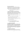
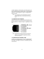
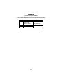
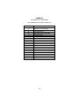
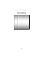
USER
MANUAL
MODEL 2707RC
NetLink-E1TM
E1 CSU/DSU Rack Card
Part# 07M2707RC-A
Doc# 086221UA
Revised 10/19/01
An ISO-9001
Certified
Company
SALES OFFICE
(301) 975-1000
TECHNICAL SUPPORT
(301) 975-1007
1.0
1.1
1.2
1.3
1.4
Warranty Information .................................................................. 4
Warranty Statement...................................................................... 4
Radio and TV Interference............................................................ 4
CE Notice...................................................................................... 5
Service Information....................................................................... 5
2.0
2.1
2.2
General Information..................................................................... 6
Features........................................................................................ 6
General Product Description......................................................... 6
3.0
3.1
Configuration ............................................................................... 7
DIP Switch Configuration.............................................................. 7
Switch S1-1 through S1-8............................................................. 8
Switch S1-1: Line Coding ............................................................. 8
Switch S1-3: Line Build-out Impedance........................................ 9
S1-6 and S1-7 Clock Modes......................................................... 9
Switch S1-8: Loopback tests ...................................................... 10
Switch S3: DIP switch or NMS (network management
system) control ......................................................................... 10
Hardware Reset .................................................................. 10
NMS Control. ....................................................................... 10
Setting the card address. .................................................... 11
DCE/DTE selector (X.21 version only) ....................................... 12
Configuring The Rear Interface Card.......................................... 12
Model 1001RCM12548C Strap Settings .................................... 14
DTE Shield (DB-25 Pin 1) & FRGND (JB3) ......................... 15
SGND & FRGND (JB4) ....................................................... 15
Model 1001RCM13448C Strap Settings .................................... 16
DTE Shield (M/34 Pin A) & FRGND (JB3). ......................... 17
SGND & FRGND (JB4). ...................................................... 17
Model 1001RCM11548C Strap Settings .................................... 17
DTE Shield (DB-15 Pin 1) & FRGND (JB3) ......................... 18
SGND & FRGND (JB4) ....................................................... 19
Model 1001RCM11575 Strap Settings ....................................... 19
3.2
3.3
4.0
4.1
4.2
4.3
4.4
4.5
4.6
5.0
5.1
5.2
Installation.................................................................................. 21
The Model 1001R14 Rack Chassis ............................................ 21
The Rack Power Supply ............................................................. 21
Powering up Your 1001R14 Rack .............................................. 22
Installing The Model 2707RC Into The Chassis ......................... 22
Connecting to a DTE Device ...................................................... 22
Connecting to a DCE Device ...................................................... 22
Connecting the E1 Interface ....................................................... 23
Connecting Dual Coax BNC (75 Ohm) ....................................... 23
Operation.................................................................................... 24
LED Descriptions ........................................................................ 24
LOCAL LOOP DIAGNOSTICS ................................................... 25
Operating local loopback (LLB) .................................................. 25
2
A
Specifications ............................................................................ 26
B
Cable Recommendations.......................................................... 27
C
Factory Replacement Parts And Accessories ........................ 28
D
E1 Interface Pin Assignment .................................................... 29
E
V.35 Interface Pin Assignment ................................................. 30
F
EIA-530 Interface Pin Assignment ........................................... 31
G
X.21 Interface Pin Assignment ................................................. 32
3
1.0 WARRANTY INFORMATION
Thank you for your purchase of this Patton Electronics product. This
product has been thoroughly inspected and tested and is warranted for
One Year parts and labor. If any questions or problems arise during
installation or use of this product, please do not hesitate to contact Patton Electronics Technical Services at (301) 975-1007.
1.1 WARRANTY STATEMENT
Patton Electronics warrants all Model 2707RC Series components to
be free from defects, and will—at our option—repair or replace the product should it fail within one year from the first date of shipment. This warranty is limited to defects in workmanship or materials, and does not
cover customer damage, abuse, or unauthorized modification. This product contains no serviceable parts; therefore the user shall not attempt to
modify the unit in any way. If this product fails or does not perform as
warranted, your sole recourse shall be repair or replacement as
described above. Under no condition shall Patton Electronics be liable
for any damages incurred by the use of this product. These damages
include, but are not limited to, the following: lost profits, lost savings and
incidental or consequential damages arising from the use of or inability to
use this product. Patton Electronics specifically disclaims all other warranties, expressed or implied, and the installation or use of this product
shall be deemed an acceptance of these terms by the user. In the event
the user detects intermittent or continuous product malfunction due to
nearby high power transmitting radio frequency equipment, the user is
strongly advised to use only data cables with an external outer shield
bonded to a metal or metallized connector.
1.2 RADIO AND TV INTERFERENCE
The Model 2707RC generates and uses radio frequency energy, and if
not installed and used properly—that is, in strict accordance with the
manufacturer's instructions—may cause interference to radio and television reception. The Model 2707RC has been tested and found to comply
with the limits for a Class A computing device in accordance with the
specifications in Subpart B of Part 15 of FCC rules, which are designed
to provide reasonable protection from such interference in a commercial
installation. However, there is no guarantee that interference will not
occur in a particular installation. If the Model 2707RC does cause interference to radio or television reception, which can be determined by disconnecting the cables, the user is encouraged to try to correct the
interference by one or more of the following measures: moving the computing equipment away from the receiver, re-orienting the receiving
antenna, and/or plugging the receiving equipment into a different AC outlet (such that the computing equipment and receiver are on different
branches).
4
1.3 CE NOTICE
The CE symbol on your Patton Electronics equipment indicates that it is
in compliance with the Electromagnetic Compatibility (EMC) directive of
the European Union (EU). A Certificate of Compliance is available by
contacting Patton Electronics Technical Support.
1.4 SERVICE INFORMATION
All warranty and non-warranty repairs must be returned freight prepaid
and insured to Patton Electronics. All returns must have a Return Materials Authorization number on the outside of the shipping container. This
number may be obtained from Patton Electronics Technical Support at:
tel: (301) 975-1007
email: [email protected]
www: http://www.patton.com
Note
Packages received without an RMA number will not be
accepted.
Patton Electronics' technical staff is also available to answer any questions that might arise concerning the installation or use of your Patton
Model 2707RC. Technical Services hours: 8AM to 5PM EST, Monday
through Friday.
5
2.0 GENERAL INFORMATION
Thank you for your purchase of this Patton Electronics product. This product has been thoroughly inspected and tested and is warranted for One
Year parts and labor. If any questions arise during installation or use of the
unit, contact Patton Electronics Technical Services at (301) 975-1007.
2.1 FEATURES
• Terminates E1/G.703 circuits over a 4-wire RJ-48C interface
• Connects to standard CPE serial and 10Base-T interfaces
• Unstructured rate of 2.048 Mbps (G.703)
• Selectable AMI or HDB3 line coding
• Configuration via internal DIP switches or SNMP management of local
unit through the 1001MC
• Six easy-to-read LED indicators monitor data and diagnostics
• Internal, external, network clocking
• also operates as a high-speed point-to-point modem
• Fits into Patton’s 2U rack-mount chassis
• Made in USA
• Conforms to ONP requirement CTR12 for connection to international
telecom networks
2.2 GENERAL PRODUCT DESCRIPTION
The Model 2707RC Series are single port E1 CSU/DSUs that provide
high-speed WAN connectivity in a rack card package. Connecting to the
serial WAN port of a switch, router or multiplexer, the NetLink-E1™ provides E1 access connection at data rates of 2.048 Mbps. The NetLinkE1™ is an excellent choice when terminating leased line services, Frame
Relay backbones, internet access as well as LAN-to-LAN services.
The Netlink-E1™ provides digital access to local WAN services between
two facilities over a dedicated 4-Wire circuit. Clock modes, line impedance, and coding options are programmed via internally accessible DIP
switches or SNMP manageable through the 1001MC. The Netlink-E1™
uses AMI and HDB3 line coding. Netlink-E1™ also supports a full range
of system and diagnostic features that make system setup easy.
The NetLink-E1 provides E1 terminations over a modular RJ-48C jack or
dual 75 Ohm BNC connectors when using the 1001RCM11575 (X.21)
rear card.
6
3.0 CONFIGURATION
The 2707RC features configuration capability via hardware DIP switches
or SNMP through Patton’s Model 1001MC Management Card. This section describes all possible hardware and software switch configurations
of the network connection.
Note
The 2707RC factory default is set to DIP switch control. Software control can be enabled by setting S3 to a valid address
SNMP management station. Performing a hardware reset sets
the unit for dip switch control.
3.1 DIP SWITCH CONFIGURATION
The Model 2707RC has two eight bit DIP switches that allow configuration for a wide range of applications. The switches are accessed by
removing the card from the chassis.Figure 1 shows the location of the
DIP switches on the top of the printed circuit board.
ON
1
ON
2
3
4
5
S3
6
7
8
1
2
3
4
5
6
7
8
S1
Figure 1. Model 2707RC Series top view, showing location of DIP switches.
DIP Switches S1 and S3 can be configured as either “On” or “Off”.
Figure 2 shows the orientation of the DIP switches with respect to ON/
OFF positions. Default position and descriptions for Switches S1 and S3
are provided on the next page.
7
Figure 2. Close up of DIP switches showing ON/OFF positions.
Note
If you do not have a terminal, you may force the unit to use the
DIP switches as the default configuration source by turning off
the unit, setting all the DIP switches to the ON position, then
powering on the unit. This will cause the unit to enter a special
mode. Then turn off the unit and change the switch settings to
the desired settings. When you turn the unit on again, the unit
will be set up with the selected switch settings.
Switch S1-1 through S1-8
A detailed description of each switch (S1-1 through S1-8) setting follows
the summary table below.
Table 1: Switch Set 1 Summary
Position
Function
Factory Default
S1-1
S1-2
S1-3
S1-4
S1-5
S1-6
S1-7
S1-8
Line Coding
Reserved
Line Build Out
Reserved
Reserved
Clocking Mode
Clocking Mode
TM from DTE
OFF
OFF
OFF
OFF
OFF
OFF
OFF
OFF
Selected
Option
HDB3
120 ohm
Network
Network
Enabled
Switch S1-1: Line Coding
Use switch S1-1 to control the network line coding. Set these options to
be the same as the line coding given to you by your service provider. If
8
you are using two Model 2707s together as short-range modems, set
both units to HDB3.
Table 2: S1-1 Line Coding settings
S1-1
Line Coding
Off
On
HDB3
AMI
Switch S1-3: Line Build-out Impedance
Switch S1-3 is used to select line build-out (LBO) impedance for the Model
2707’s E1 port. Your Model 2707RC comes equipped with either an RJ-48C
connector, dual BNC connectors, or both. When connecting to the E1 network, the LBO selection must match the connector type. If the dual BNC connectors are used, the line build-out impedance must be set to 75-ohm.
Otherwise, for the RJ-48C connector, impedance should be set to 120 ohm.
Table 3: S1-3 Line Build-out settings
S1-3
Setting
75 ohm
120 ohm
On
Off
S1-6 and S1-7 Clock Modes
Set switch S1-6 and S1-7 to determine the 2707RC’s transmitter timing.
Table 4: S1-6 and S1-7 Clock Modes
S1-6
S1-7
Clock Mode
On
On
Off
Off
On
Off
On
Off
Network (Received Recovered)
Internal
External
Network (Received Recovered)
Network Clock
Internal Clock
External Clock
Transmitter timing is derived using the received
line signal (received recovered) from the network.
Transmitter timing is derived from an internal clock
source.
Transmitter timing is derived from DTE terminal
timing. (Units equipped with 10Base-T modules do
not operate in external clock mode. They enter
internal clock mode when this setting is selected.)
9
Switch S1-8: Loopback tests
Use switch S1-8 to allow the Model 2707RC to enter loopbact test mode
when the DTE raises the appropriate loop request pin.
Table 5: S1-8 Loopback test settings
S1-8
Setting
Off
On
DTE loopback request enabled
DTE loopback request disabled
Switch S3: DIP switch or NMS (network management system) control
The Model 2707RC can be configured and managed via DIP switches, or
NMS-SNMP/HTTP through a Patton Model 1001MC management card
acting as a proxy agent. (refer to the 1001MC user manual when using
this mode). Switch S3 selects control and management mode for the
Model 2707RC.
Table 6: S3 DIP switch settings
S3-1 to S3-8
Management selection
All set to Off
All set to On
DIP switch control (factory default)
Hardware reset
Hardware Reset . The Model 2707RC is set at the factory for DIP switch
control. If the user has changed control to NMS, and then needs to revert
to DIP switch control, use the following procedure:
1. Pull the Model 2707RC out of the rack.
2. Set all switches (S1 and S3) to the ON position.
3. Install the card into the rack and power up the unit.
4. Pull the card out again and change the switches to the desired settings. The unit is now under DIP switch control.
5. Install the card back into the rack.
NMS Control. When switches S3-1 to S3-8 are set to a setting other
than the ones shown in Table 6, the Model 2707RC enters NMS control.
While under NMS control, each of the Model 2707RC cards housed in a
rack must have an address. Table 7 and Figure 3 show examples of
address settings. The table follows the hexadecimal system, where
switch SW3-1 is the least significant bit (LSB), and SW3-8 is the most
10
significant bit (MSB). A switch in the On position represents binary zero,
and Off represents binary one (see Figure 3).
Table 7: Examples of the address settings
Hex Address
(Decimal Address)
S3-8
S3-7
S3-6
S3-5
S3-4
S3-3
S3-2
S3-1
0x01 (1)
0x02 (2)
0x10(16)
0xB5(181)
ON
ON
ON
OFF
ON
ON
ON
ON
ON
ON
ON
OFF
ON
ON
OFF
OFF
ON
ON
ON
ON
ON
ON
ON
OFF
ON
OFF
ON
ON
OFF
ON
ON
OFF
Hexadecimal
Address
Decimal
Address
0x01 (1)
1
Least significant bit (MSB)
Most significant bit (LSB)
ON
1
2
3
4
5
6
7
8
2
3
4
5
6
7
8
2
3
4
5
6
7
8
2
3
4
5
6
7
8
On = binary 0
Off = binary 1
ON
0x02 (2)
2
1
ON
0x10 (16)
16
1
ON
0xB5 (181)
181
1
Figure 3. Sample DIP switch settings
Setting the card address. Table 7 and Figure 3 show examples of how
to set a card address using switches S3-1 through S3-8. The addresses
are listed in their hexadecimal (hex) and corresponding decimal values.
11
1
TM
Link
TXD
ON
RXD
Model 2707RC
In this example, the DCE/DTE
strap is configured for DTE
because the DTE label on the
strap is pointed toward the
front panel
ON
1
2
3
4
5
6
7
2
3
4
5
6
7
8
8
Figure 4. DCE/DTE selector strap location
3.2 DCE/DTE SELECTOR (X.21 VERSION ONLY)
The X.21 version of the 2707RC can be set up as a DCE (default) or
DTE device by using a DCE/DTE selector strap (see Figure 4). The information in Table 8 describes configuring the DCE/DTE strap.
Table 8: DCE/DTE selector settings
Setting
Description
DCE
To set a rack card as a DCE device, install the DCE/DTE
selector with the DCE arrows pointing toward the front
panel.
To set a rack card as a DTE device, install the DCE/DTE
selector with the DTE arrows pointing toward the front
panel.
DTE
3.3 CONFIGURING THE REAR INTERFACE CARD
The Model 2707RC Series has five interface card options: the Model
1001RCM12548C (DB-25/RJ-48C), the Model 1001RCM13448C (M/34/
RJ-48C), the Model 1001RCM11548C (DB-15/RJ-48C), the Model
1001RCM11575 (DB-15/Dual BNC), and the model IM2RC/IA (RJ-48C/
12
RJ-45). Each of these options supports one DTE interface connection
and one 4-wire RJ-48C or dual-BNC line connection. Figure 5 illustrates
the five different interface options for the Model 2707RC Series.
Model
Model
Model
Model
1001RCM11575 1001RCM11548C 1001RCM12548C 1001RCM13448C
Dual BNC
RJ-48C
RJ-48C
RJ-48C
DB-15 F
DB-15 F
DB-25 F
Model
IM2RC/IA
RJ-48C
M/34 F
Figure 5. Model 2707RC Series interface card options.
Note
The 2707RC Series rear cards are specifically designed to
operate with the E1 function card and must not be swapped with
other Patton function cards.
Prior to installation, you will need to examine the rear card you have
selected and make sure it is properly configured for your application.
Each rear card is configured by setting straps located on the PC board.
To configure the rear cards, you must set the configuration straps.
Figure 6 shows the orientation of these straps. Each strap can either be
on pins 1 and 2, or on pins 2 and 3.
Figure 6. Orientation of Interface Card Straps
Sections “Model 1001RCM12548C Strap Settings”,“Model
1001RCM13448C Strap Settings”, and “Model 1001RCM11548C Strap
13
Settings” describe the strap locations and possible settings for each rear
card.
Model 1001RCM12548C Strap Settings
Figure 7 shows strap locations for the Model 1001RCM12548C (DB-25)
rear cards. These straps determine various grounding characteristics for
the terminal interface and twisted pair lines. JB3 and JB4 are user configurable.
1
3
JB
3
4
JB
1
2
3
Figure 7. 1001RCM125XX strap locations.
Table 9 provides an overview of interface strap functions for the rear
interface cards. Following the table overview are detailed descriptions of
each strap’s function.
Table 9: Interface Card Strap Summary
Strap
JB3
JB4
Function
Position 1&2
DTE Shield (Pin1) & FRGND
Connected*
FRGND & SGND
Connected*
* Indicates default setting
14
Position 2&3
Open
Open
DTE Shield (DB-25 Pin 1) & FRGND (JB3). In the connected position,
this strap links DB-25 pin 1 & frame ground. In the open position, pin 1 is
disconnected from frame ground (see Table 10)
Table 10: JB3 strap settings
Position
Description
1&2
2&3
SGND (Pin 7) and FRGND Connected through a 100 ohm resistor
DTE Shield (Pin 1) and FRGND Not Connected
SGND & FRGND (JB4). In the connected position, this strap links DB-25
pin 7 (Signal Ground) and frame ground through a 100 ohm resistor. In
the open position, pin 7 is connected directly to frame ground (see
Table 11)
Table 11: JB4 strap settings
Position
Description
1&2
2&3
SGND (Pin 7) and FRGND Connected through a 100 ohm resistor
SGND (Pin 7) and FRGND Directly Connected
15
Model 1001RCM13448C Strap Settings
Figure 8 shows the strap location for the Model 1001RCM13448C (M/34)
rear card. This strap determines whether Signal Ground and Frame
Ground will be connected.
1
JB
3
3
4
JB
1
2
3
Figure 8. 1001RCM13448C strap locations.
Table 12 provides an overview of interface strap functions for the rear
interface cards. Following the table overview are detailed descriptions of
each strap’s function.
Table 12: Interface Card Strap Summary
Strap
JB3
JB4
Function
Position 1&2
DTE Shield (Pin A) & FRGND
Connected*
FRGND & SGND (Pin B)
Connected*
* Indicates default setting
16
Position 2&3
Open
Open
DTE Shield (M/34 Pin A) & FRGND (JB3). In the connected position,
this strap links M/34 pin A & frame ground. In the open position, pin A is
disconnected from frame ground (see Table 13).
Table 13: JB3 strap settings
Position
1&2
2&3
Description
DTE Shield (Pin A) and FRGND Connection
DTE Shield (Pin A) and FRGND Not Connected
SGND & FRGND (JB4). In the connected position, this strap links Signal
Ground and frame ground through a 100 ohm resistor. In the open position, signal ground is disconnected from frame ground (see Table 14).
Table 14: JB4 strap settings
Position
1&2
2&3
Description
SGND and FRGND Connected
SGND and FRGND Not Connected
Model 1001RCM11548C Strap Settings
Figure 9 on page 18 shows strap locations for the Model
1001RCM11548C (DB-15) rear cards. These straps determine various
grounding characteristics for the terminal interface and twisted pair lines.
JB3 and JB4 are user configurable.
17
1
JB
3
3
4
JB
1
2
3
Figure 9. 1001RCM11548C strap locations.
Table 15 provides an overview of interface strap functions for the rear
interface cards. Following the table overview are detailed descriptions of
each strap’s function.
Table 15: Interface Card Strap Summary
Strap
JB3
JB4
Function
Position 1&2
DTE Shield (Pin1) & FRGND
Connected*
FRGND & SGND (Pin 8)
Connected*
* Indicates default setting
Position 2&3
Open
Open
DTE Shield (DB-15 Pin 1) & FRGND (JB3). In the connected position,
this strap links DB-15 pin 1 & frame ground. In the open position, pin 1 is
disconnected from frame ground (see Table 16).
Table 16: JB3 strap settings
Position
1&2
2&3
Description
DTE Shield (Pin 1) and FRGND Connected
DTE Shield (Pin 1) and FRGND Not Connected
18
SGND & FRGND (JB4). In the connected position, this strap links DB-15
pin 8 (Signal Ground) and frame ground through a 100 ohm resistor. In
the open position, pin 8 is connected directly to frame ground
(see Table 17).
Table 17: JB4 strap settings
Position
Description
1&2
2&3
SGND (Pin 8) and FRGND Connected through a 100 ohm resistor
SGND (Pin 8) and FRGND Directly Connected
Model 1001RCM11575 Strap Settings
Figure 10 shows strap locations for the Model 1001RCM11575 (DB-15/
Dual BNC) rear cards. Figure 8 shows strap locations for the Model
1001RCM11548C (DB-15) rear cards. These straps determine various
grounding characteristics for the terminal interface and twisted pair lines.
JB3 and JB4 are user configurable.
3
JB
B4
J
1
3
1
3
Figure 10. 1001RCM11575 strap locations.
19
.
Table 18: Interface Card Strap Summary
Strap
JB3
JB4
Function
Position 1&2
DTE Shield (Pin1) & FRGND
Connected*
FRGND & SGND (Pin 8)
Connected*
* Indicates default setting
20
Position 2&3
Open
Open
4.0 INSTALLATION
This section describes the functions of the Model 1001R14 rack chassis,
tells how to install front and rear Model 2707RC Series cards into the
chassis, and how to connect to the twisted pair interface and the serial
interface.
4.1 THE MODEL 1001R14 RACK CHASSIS
The Model 1001R14 Rack Chassis (Figure 9, below) has fourteen or sixteen device card slots, plus a single power supply or dual redundant
power supplies. Measuring only 3.5” high, the Model 1001R14 is
designed to occupy only 2U in a 19” rack. Sturdy front handles allow the
Model 1001R14 to be extracted and transported conveniently.
Figure 11. Model 1001R14 Rack Chassis with power supply.
The Rack Power Supply
The power supply included in the Model 1001R14 rack uses the same
mid-plane architecture as the modem cards. The front card of the power
supply slides in from the front, and the rear card slides in from the rear.
They plug into one another in the middle of the rack. The front card is
then secured by thumb screws and the rear card by conventional metal
screws.
WARNING
There are no user-serviceable parts in the power supply section of the Model 1001R14 rack. Voltage setting changes and fuse replacement should only be
performed by qualified service personnel. Contact
Patton Electronics Technical support at +1 (301) 9751007, via our web site at www.patton.com, or by Email at [email protected], for more information.
21
Powering up Your 1001R14 Rack
The power supplies that come with your 1001R14 rack system are
equipped with a power entry connector on the rear power supply card.
The power supplies are Hot-Swappable, so you are not required to
remove the cards from the rack while applying power to the system.
Note
Please refer to the Model 1001R14 Series User Manual AC and
DC Rack Mount Power Supplies for fuse and power card
replacement information.
4.2 INSTALLING THE MODEL 2707RC INTO THE CHASSIS
The Model 2707RC is comprised of a front card and a rear card. The two
cards meet inside the rack chassis and plug into each other by way of
mating 50 pin card edge connectors. Use the following steps as a guideline for installing each Model 2707RC into the rack chassis:
1. Slide the rear card into the back of the chassis along the metal rails
provided.
2. Secure the rear card using the metal screws provided.
3. Slide the card into the front of the chassis. It should meet the rear
card when it’s almost all the way into the chassis.
4. Push the front card gently into the card-edge receptacle of the rear
card. It should “click” into place.
5. Secure the front card using the thumb screws.
Note
Since the Model 1001R14 chassis allows “hot swapping” of
cards, it is not necessary to power down the rack when you
install or remove a Model 2707RC.
4.3 CONNECTING TO A DTE DEVICE
The serial port on most rear interface cards are hard-wired as “DCE”
(data communications equipment). The interfaces are designed to plug
into a DTE such as a terminal, PC or host computer. When making the
connection to your DTE device, use a “straight through” cable of the
shortest possible length--we recommend 6 feet or less. When purchasing or constructing an interface cable, please refer to the pin diagrams in
Appendix E on page 30, Appendix F on page 31, and Appendix G on
page 32 as guides.
4.4 CONNECTING TO A DCE DEVICE
The rear interface cards on most interface modules are hard wired as
“DCE”. Therefore, you must use a null modem cable when connecting to
22
a modem, multiplexer or other DCE device. This cable should be of the
shortest possible length--we recommend 6 feet or less. When purchasing or constructing a null modem interface cable, use the pin diagrams in
Appendix E on page 30, Appendix F on page 31, and Appendix G on
page 32 as guides.
Note
Pin-out requirements for null modem applications vary between
equipment manufacturers. If you have any questions about a
specific installation, please contact Patton Electronics Technical
Support.
4.5 CONNECTING THE E1 INTERFACE
The Network Line Interface is an eight position keyed modular jack configured as a RJ-48C. This interface will need to be configured to match
the line parameters (i.e. framing, line coding, etc.) supplied by the central
office.
Figure 12. NetLink-E1™ twisted pair line interface.
Note
If the NetLink-E1™ is being used for private short range modem
applications, the twisted pair cable connected to its port will
need to be a cross-over cable. See Appendix D on page 29 for
Interface pin assignments.
4.6 CONNECTING DUAL COAX BNC (75 OHM)
In addition to the 120 Ohm twisted pair connection, the Model 2707RC,
when used with the 1001RCM11575 rear card, is equipped with dual
female BNCs (TX and RX) for connection to a 75 ohm dual coax G.703
network interface.
23
5.0 OPERATION
Once the NetLink-E1™ is installed and configured properly it is ready to
place into operation. This section describes the function of the LED indicators, and the use of the loopback and pattern test modes.
5.1 LED DESCRIPTIONS
The NetLink-E1™ is equipped with nine LED indicators that monitor the
status of communication. Figure 13 shows the location of the LEDs on
the NetLink-E1™ Series front panel.
Model 2707RC
TXD
RXD
Link
TM
LLB
Figure 13. Model 2707RC front panel, showing LED indicators.
TXD
RXD
Link
TM
When the unit sends a one, the TXD LED is green. When it
sends a zero, the TXD LED is yellow. Moreover, the TXD
LED is active only in active DS0 channels. In inactive channels, the TXD LED is off.
When the unit receives a one, the RXD LED is green.
When it receives a zero, the RXD LED is yellow. Moreover,
the RXD LED is active only in active DS0 channels. In
inactive channels, the RXD LED is off.
The Link LED is green when it detects a live E1 network
connection by the 2707RC’s E1 port. The Link LED
remains off if there is no connection to the E1 network.
The Test Mode LED will briefly blink yellow to indicate that
the Model 2707RC is in local loopback mode.
24
5.2 LOCAL LOOP DIAGNOSTICS
The NetLink-E1 offers local loop diagnostics. Local loop is useful when
isolating installation or performance problems. The Model 2707RC local
loop is initiated via the front panel toggle switch labeled LLB.
Operating local loopback (LLB)
The local loopback (LLB) test checks the operation of the local NetLinkE1, and is performed separately on each unit. Any data sent to the local
NetLink-E1 in this test mode will be echoed (returned) to the user device
(for example, characters typed on the keyboard of a terminal will appear
on the terminal screen)
To perform an LL test, do the following:
1. Activate LL. This can be done in any of the following ways:
—
Enter Local Loop from the NMS Diagnostics/Statistics menu
and select the Local Loop option from the drop-down menus
—
Activate the LL signal on the DTE. If you are not sure which
lead is the LL signal, refer to Appendix D on page 29
—
Toggle the front panel switch to the Local position
2. Verify that the data terminal equipment is operating properly and
can be used for a test.
3. Perform a BER test (bit error rate). If the BER test equipment indicates no faults, but the data terminal indicates a fault, follow the
manufacturer’s checkout procedures for the data tereminal. Also,
check the interface cable between the terminal and the NetLink-E1.
25
APPENDIX A
SPECIFICATIONS
Network Data Rate:
Network Connector:
Nominal Impedance:
DTE Interface:
Line Coding:
Line Framing:
Clocking:
DTE Data Rate:
Indicators:
Configuration:
Powered by 1001R14
Rack Power Supply:
Humidity:
Temperature:
Dimensions:
2.048 Mbps
RJ-48C or dual BNC
120 ohm (75 ohm available when using Patton Model 1001RCM11575 rear card)
V.35, X.21 (DCE or DTE orientation),
10Base-T, Ethernet
Selectable AMI or HDB3
G.703 (Unframed)
Internal, External, or Receive Recover
2.048 Mbps
Transmit Data, Receive Data, Test Mode,
Link
Two 8-Position DIP Switches or SNMP Manageable
100–240 VAC, 50–60 Hz
Up to 90% non-condensing
0 to 50º C (32–122°F)
9.0L x 5.3W x 2.0H cm
(3.5L x 2.1W x 0.78H)
26
APPENDIX B
CABLE RECOMMENDATIONS
The Patton NetLink E1™ Series has been performance tested by Patton
technicians using twisted-pair cable with the following characteristics:
Wire Gauge
Capacitance
Resistance
19 AWG
22 AWG
24 AWG
83nf/mi or 15.72 pf/ft.
83nf/mi or 15.72 pf/ft.
83nf/mi or 15.72 pf/ft.
.0163 Ohms/ft.
.0326 Ohms/ft.
.05165 Ohms/ft.
To gain optimum performance from the Model 2707RC Series, please
keep the following guidelines in mind:
• Always use twisted pair wire—this is not an option.
• Use twisted pair wire with a capacitance of 20pf/ft or less.
• Avoid twisted pair wire thinner than 26 AWG (i.e. avoid AWG numbers
higher than 26).
• Use of twisted pair with a resistance greater than the above specifications may cause a reduction in maximum distance obtainable. Functionality should not be affected.
• Many environmental factors can affect the maximum distance obtainable at a particular site.
27
APPENDIX C
FACTORY REPLACEMENT PARTS AND ACCESSORIES
Patton Model #
2707RC/D/V
2707RC/B/B
2707RC/A/I
1001RPEM-RAC
1001RPEM-RAC
1001RPSM-RUI
1001RPEM-RDC
1001RPSM-R48A
1001R14P
1001R14P/R48V
1001R14P/RUIA
1001R14P/RUIC
1001R14P/RUID
1001R14P/RUIG
1001R14P/RUIK
1001RCM12548C
1001RCM13448C
1001CC
IM2RC/B
05R16BP440W
05R16FP440W
0516FPB1
0516FPB4
0516RPB1
0516RPB4
056S1
10-25M/35M-1
1010-10
07M2707RC
Description
E1/FE1 CSU/DSU Rack Card, X.21 Interface w/
DB15FS/RJ48C rear card
E1/FE1 CSU/DSU Rack Card, RS530\ Interface with
DB25F/RJ48C Rear Card
E1/FE1 CSU/DSU Rack Card, V.35 Interface with M/
34F/RJ48C Rear Card
120/240V Rear Power Entry Module
120/240V Rear Power Entry Module
120/240V Front Power Supply Module
DC Rear Power Entry Module
48V Front Power Supply Module
Rack 14 Slot 2U Chassis Only
Rack 14 Slot 2U w/Dual Universal Input 48VDC
Power Supplies
Rack 14 Slot 2U w/Dual Universal Input 90-260VAC
Power Supplies European Power Cord
Rack 14 Slot 2U w/Dual Universal Input 90-260VAC
Power Supplies Australia Power Cord
Rack 14 Slot 2U w/Dual Universal Input 90-260VAC
Power Supplies UK Power Cord
Rack 14 Slot 2U w/Dual Universal Input 90-260VAC
Power Supplies India Power Cord
Rack 14 Slot 2U w/Dual Universal Input 90-260VAC
Power Supplies US Power Cord
DB-25/RJ-45 Rear Card
M/34/RJ-45 Rear Card
Control Card
RS-530 Interface Rear Card
Single Width Blank Rear Panel, White
Single Width Blank Front Panel, White
Single Width Blank Front Panel, Black
4-Wide Blank Front Panel, Black
Single Width Blank Rear Panel, Black
4-Wide Blank Rear Panel, Black
Set of 16 #4 pan head screws/washers
Cable, 6 ft, DB-25 male to M/34 male
Terminal Block, 2 Position, Male
User Manual
28
APPENDIX D
E1 INTERFACE PIN ASSIGNMENT
RJ-48C E1 (DS0) NETWORK INTERFACE (FEMALE MODULAR JACK)
Pin #
Signal
1
2
RX Data (TIP 1)
RX Data (RING1)
4
5
TX Data (TIP)
TX Data (RING)
}
}
From Network
To Network
29
APPENDIX E
V.35 INTERFACE PIN ASSIGNMENT
M/34 CONNECTOR, TERMINAL INTERFACE
Pin #
Signal
A
B
D
E
F
L
M
N
P
R
S
T
U
V
W
X
Y
AA
GND (Earth Ground/Shield)
SGND (Signal Ground)
CTS (DCE Source)
DSR (DCE Source, Always On)
CD (DCE Source)
LL (Local Loop, DTE Source)
TM (Test Mode Indicator, DCE Source)
RL (Remote Loop, DTE Source)
TD (Transmit Data +, DTE Source)
RD (Receive Data +, DCE Source)
TD/ (Transmit Data -, DTE Source)
RD/ (Receive Data -, DCE Source)
XTC (Transmit Clock +, DTE Source)
RC (Receiver Clock +, DCE Source)
XTC/ (Transmit Clock -, DTE Source)
RC/ (Receiver Clock -, DCE Source)
TC (Transmitter Clock +, DCE Source)
TC/ (Transmitter Clock -, DCE Source)
30
APPENDIX F
EIA-530 INTERFACE PIN ASSIGNMENT
DB-25 FEMALE CONNECTOR, TERMINAL INTERFACE
Pin #
1
2
3
4
5
6
7
8
9
10
11
12
13
14
15
16
17
18
19
20
21
22
23
24
25
Signal
FG (FrameGround)
TD (Transmit Data-A, DTE Source)
RD (Receive Data-A, DCE Source)
RTS (Request to Send-A, DTE Source)
CTS (Clear to Send-A, DCE Source)
DSR (Data Set Ready-A, DCE Source)
SGND (Signal Ground)
CD (Carrier Detect-A, DCE Source)
RC/ (Receiver Clock-B, DCE Source)
CD/ (Carrier Detect-B, DCE Source)
XTC/(External Transmitter Clock-B, DTE Source)
TC/(Transmitter Clock-B, DCE Source)
CTS/(Clear to Send-B, DCE Source)
TD/(Transmit Data-A, DTE Source)
TC (Transmitter Clock-A, DCE Source)
RD (Receive Data-A, DCE Source)
RC (Receiver Clock-A, DCE Source)
LL (Local LIne Loop)
RTS/(Request to Send-B, DTE Source)
DTR (Data Terminal Ready-A, DTE Source)
RL (Remote Loopback)
DSR/ (Data Set Ready-B, DCE Source)
DTR/(Data Terminal Ready-B, DTE Source)
XTC (External Transmitter Clock-A, DTE Source)
TM (Test Mode)
31
APPENDIX G
X.21 INTERFACE PIN ASSIGNMENT
(DB-15 FEMALE CONNECTOR)
(DTE /DCE CONFIGURATION)
Pin #
1
2
3
4
5
6
7
8
9
10
11
12
13
14
Signal
Frame Ground
T (Transmit Data-A)
C (Control-A)
R (Receive Data-A)
I (Indication-A)
S (Signal Element Timing-A)
BT (Byte Timing-A)
SGND (Signal Ground)
T/ (Transmit Data-B)
C/ (Control-B)
R/ (Receive Data-B)
I/ (Indication-B)
S/ (Signal Element Timing-B)
BT/ (Byte Timing-B)
32