1
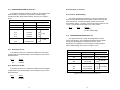
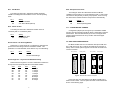
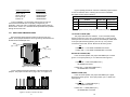
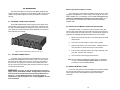
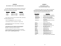
USER
MANUAL
MODEL 1018RC
Powered High Speed
Short Range Modem:
Rack Mount Card
Part# 07M1018RC-C
Doc# 013012UC
Revised 2/4/97
CERTIFIED
An ISO-9001
Certified Company
SALES OFFICE
(301) 975-1000
TECHNICAL SUPPORT
(301) 975-1007
http://www.patton.com
1.0 WARRANTY INFORMATION
1.3 SERVICE
Patton Electronics warrants all Model 1018RC components to be
free from defects, and will—at our option—repair or replace the product
should it fail within one year from the first date of shipment.
This warranty is limited to defects in workmanship or materials, and
does not cover customer damage, abuse or unauthorized modification.
If this product fails or does not perform as warranted, your sole
recourse shall be repair or replacement as described above. Under no
condition shall Patton Electronics be liable for any damages incurred
by the use of this product. These damages include, but are not limited
to, the following: lost profits, lost savings and incidental or
consequential damages arising from the use of or inability to use this
product. Patton Electronics specifically disclaims all other warranties,
expressed or implied, and the installation or use of this product shall be
deemed an acceptance of these terms by the user.
All warranty and nonwarranty repairs must be returned freight
prepaid and insured to Patton Electronics. All returns must have a
Return Materials Authorization number on the outside of the shipping
container. This number may be obtained from Patton Electronics
Technical Support: (301) 975-1007; http://www.patton.com; or,
[email protected]. Notice: Packages received without an RMA
number will not be accepted. Patton Electronics' technical staff is also
available to answer any questions that might arise concerning the
installation or use of your Model 1018RC. Technical Service hours:
8AM to 5PM EST, Monday through Friday.
1.1 RADIO AND TV INTERFERENCE
The Model 1018RC generates and uses radio frequency energy,
and if not installed and used properly—that is, in strict accordance with
the manufacturer’s instructions—may cause interference to radio and
television reception. The Model 1018RC has been tested and found to
comply with the limits for a Class A computing device in accordance
with the specifications in Subpart J of Part 15 of FCC rules, which are
designed to provide reasonable protection from such interference in a
commercial installation. However, there is no guarantee that
interference will not occur in a particular installation. If the Model
1018RC does cause interference to radio or television reception, which
can be determined by turning the power off or removing the card, the
user is encouraged to try to correct the interference by one or more of
the following measures: moving the computing equipment away from
the receiver, re-orienting the receiving antenna and/or plugging the
receiving equipment into a different AC outlet (such that the computing
equipment and receiver are on different branches). In the event the user
detects intermittent or continuous product malfunction due to nearby
high power transmitting radio frequency equipment, the user is strongly
advised to take the following steps: use only data cables with an
external outer shield bonded to a metal or metalized connector; and,
configure the rear card as shown in section 3.2.1 of this manual.
1.2 CE NOTICE
The CE symbol on your Patton Electronics equipment indicates
that it is in compliance with the Electromagnetic Compatibility (EMC)
directive and the Low Voltage Directive (LVD) of the Union European
(EU). A Certificate of Compliance is available by contacting Technical
Support.
1
2
2.0 GENERAL INFORMATION
Thank you for your purchase of this Patton Electronics product.
This product has been thoroughly inspected and tested and is
warranted for One Year parts and labor. If any questions arise during
installation or use of the unit, contact Patton Electronics Technical
Support: (301) 975-1007.
2.1 FEATURES
•
•
•
•
•
•
•
•
•
•
•
Switch-selectable carrier control
Asynchronous operation
Selectable data rates from 1200 to 57,600 bps
Distances to 2.4 miles
Point-to-point operation
V.54 loopback tests and V.52 compliant BER tests
Six easy-to-read LED indicators
Transformer isolation
Silicon Avalanche Diode surge protection
Switchable 120V or 240V power supply
Mounts in Patton’s 16-card rack chassis
2.2 DESCRIPTION
3.0 CONFIGURATION
This section describes the location and orientation of the Model
1018RC’s configuration switches and jumpers, and provides detailed
instructions for all possible settings.
The Model 1018RC uses a combination of DIP switches and
jumpers that allow configuration to an extremely wide range of
applications. Designed around a mid-plane architecture, the Model
1018RC incorporates both front and rear cards. Configuration of both
may be necessary. The switches/jumpers are accessible when the
cards are slid out of the rack chassis. Once configured, the Model
1018RC is designed to operate transparently, without need for frequent
re-configuration: just set it and forget it!
3.1 FUNCTION CARD CONFIGURATION
The Model 1018RC front card has two sets of eight switches (S1 &
S2), which are mounted on the PC board (Figure 1, below). These
configuration switches allow you to configure the Model 1018RC for a
wide range of applications. The ON/OFF orientation of the DIP
switches is shown in figure 2 (below). Jumpers JP1 through JP4 are
primarily used for factory configuration, and should be left in their
default positions.
The Patton Model 1018RC short range modem rack card passes
two “session” control signals (DTR/DCD), as well as two channelindependent flow control signals (RTS/CTS). This capability makes the
Model 1018 suitable for SLIP (Serial Line Internet Protocol) and PPP
(Point-to-Point Protocol) applications, as well as other serial
applications requiring extra controls.
The Model 1018RC supports asynchronous data rates from 1.2 to
57.6 Kbps, and distances to 2.4 miles. The Model 1018RC
incorporates two V.54 test modes (local analog loop and remote digital
loop), which can be activated from the front panel via the RS-232
interface. Additionally, a built-in V.52 BER test generator can output
511 and 511E bit patterns. Five easy-to-read LED indicators monitor
power, transmit data, carrier detect, test mode and test pattern. For
protection against ground loops and transient surges, the Model
1018RC incorporates both isolation transformers and Silicon Avalanche
Diode surge suppressors.
The Model 1018RC is designed to mount in Patton’s 2U high 19”
rack chassis. This 16-card chassis has a switchable 120/240 VAC
power supply (optional 48 VDC) and mounts cards in a mid-plane
architecture: The front card can be plugged into different rear cards.
This means that the Model 1018RC card can have several interface
options and can be switched with other Patton short haul cards.
3
S1
JP1
JP2
JP3
JP4
S2
Figure 1. Model 1018RC board, showing location of switches/jumper
ON
ON
1
2
3
4
5
6
7
8
OFF
Figure 2. Close-up of DIP switches showing “ON” and “OFF” positions
4
3.1.1 CONFIGURATION SWITCH PACK “S1”
S1-3 through S1-6: Not Used
The eight DIP switches on pack S1 set Remote Test Activation and
RTS/CTS Delay. Descriptions of all possible S1 switch settings,
including the Patton factory default settings, are found on on pages 4
and 5.
S1 SUMMARY TABLE
Position
Function
Factory Default
S1-1
DTE Control of LAL
On Enabled
S1-2
DTE Control of RDL
On Enabled
S1-3
Not Used
Off
S1-4
Not Used
Off
S1-5
Not Used
Off
S1-6
Not Used
Off
S1-7
RTS/CTS Delay
Off
S1-8
RTS/CTS Delay
Off
}
N/A
}
0 mS
S1-7 and S1-8: RTS/CTS Delay
The combined settings for switches S1-7 and S1-8 determine the
amount of delay between the time the Model 1018RC “sees” RTS and
when it sends CTS. Currently, the Model 1018RC does not have
optional delay settings. “No Delay” is defined as between 500 nsec and
1 msec. The switches should remain in the “OFF” position.
S1-8
Off
S1-7
Off
3.1.2 CONFIGURATION SWITCH SET “S2”
Figure 3. Summary of DIP switch default settings for set S1
The eight DIP switches on pack S2 set Digital Reset, Carrier
Control, Link Clocking, Async Data Rate and Microprocessor Reset.
Factory default settings are summarized in Figure 4, below.
Descriptions of all possible S1 switch settings, including the Patton
factory default settings, are found on on pages 6 and 7.
S1-1: DTE Control of LAL
S2 SUMMARY TABLE
The setting for switch S1-7 determines whether the Local Analog
Loopback test on the Model 1018RC can be activated via pin 18 of the
RS-232 interface.
S1-1
On
Off
Setting
0 mS delay
No other valid settings
Setting
Enabled
Disabled
Position
Function
Factory Default
S2-1
V.54 Disable
Off
Normal
S2-2
Control of Carrier
On
Ctrl by DTR
S2-3
Link Clocking
On
S2-4
Link Clocking
On
S2-5
Async Data Rate
On
S1-2: DTE Control of RDL
S2-6
Async Data Rate
On
The setting for switch S1-7 determines whether the Remote Digital
Loopback test on the Model 1018RC can be activated via pin 21 of the
RS-232 interface.
S2-7
Async Data Rate
On
S2-8
Microprocessor Reset
Off
S1-2
On
Off
Internal
}
57.6 Kbps
Figure 4. Summary of DIP switch default settings for S2
Setting
Enabled
Disabled
5
}
6
Normal
S2-1: V.54 Disable
S2-8: Microprocessor Reset
The setting for switch S2-1 determines whether the Model
1018RC’s V.54 diagnostics are disabled or are in normal operating
mode.
The setting for switch S2-8 determines whether the Model
1018RC’s microprocessor is in normal operating mode or “reset” mode.
This switch is used primarily for factory test purposes, since removing
the card from the chassis resets the microprocessor automatically.
S2-1
On
Off
Setting
V.54 Test Disabled
V.54 Test Enabled (Normal)
Setting
Reset Mode
Normal Operating Mode
S2-8
On
Off
S2-2: Carrier Control
3.1.3 CONFIGURATION JUMPERS
The setting for switch S2-2 determines whether Carrier is
“Constantly ON” or “Controlled by DTR”.
S2-2
On
Off
Setting
Controlled by DTR
Constantly ON
3.2 REAR CARD CONFIGURATION
S2-3 and S2-4: Link Clocking Method
Switches S1-7 and S1-8 are set in combination to determine the
synchronous link clocking method for the Model 1018RC. This
parameter is not user definable, hence there is only one valid setting.
S2-1
On
S2-2
On
Configuration jumpers (JP1 through JP4) on the Model 1018RC
Function Card are primarily intended for factory configuration of the RS232 interface. We recommended that you do not re-configure these
jumpers unless instructed to do so by a Patton Technical Support
Representative.
Setting
Internal
No other valid settings
The Model 1018RC has four rear interface card options: DB-25 &
RJ-11, DB-25 & RJ-45, RJ-11 & RJ-45 and dual RJ-45 (see figure 5,
below). Each of these options supports one terminal connection and
one line connection.
RJ-11 (6-wire)
RJ-45 (8-wire)
RJ-11 (6-wire)
DB-25 F
DB-25 F
RJ-45 (8-wire)
RJ-45 (8-wire)
S2-5 through S2-7: Asynchronous Data Rate Setting
Switches S2-5 through S2-7 are set in combination to determine
the asynchronous (terminal) data rate for the Model 1018RC.
S2-5
Off
Off
Off
Off
On
On
On
On
S2-6
Off
Off
On
On
Off
Off
On
On
S2-7
Off
On
Off
On
Off
On
Off
On
Setting
1.2 Kbps
2.4 Kbps
4.8 Kbps
9.6 Kbps
19.2 Kbps
28.8 Kbps
38.4 Kbps
57.6 Kbps
7
RJ-45 (8-wire)
Figure 5. Model 1018RC interface card options
Each of the four rear card options for the Model 1018RC has a
distinct model number. The four options and their model numbers are
shown on the following page.
8
Interface Combination
Model Number
DB-25 & RJ-11
DB-25 & RJ-45
RJ-11 & RJ-45
Dual RJ-45
1000RCM12511
1000RCM12545
1000RCM1D11
1000RCM1D45
Prior to installation, you will need to examine the rear card you
have selected and make sure it is properly configured for your
application. Each rear card is configured by setting straps located on
the PC board. Section 3.5.1 describes the strap locations and possible
settings for each rear card.
Figure 8 (below) provides an overview of interface jumper functions
for the rear interface cards. Following this overview is a detailed
description of each jumper’s function.
INTERFACE CARD STRAP SUMMARY TABLE #1
Strap
Function
Position 1&2
Position 2&3
JB2
Line Shield & FRGND
Connected
Open*
JB3
DTE Shield (Pin1) & FRGND
Connected
Open*
JB4
FRGND & SGND
Connected
Open*
Figure 8. Summary of strap settings, * indicates factory default
3.2.1 REAR CARD JUMPER SETTINGS
Line Shield & FRGND (JB2)
Figure 6 (below) shows jumper locations for the four rear card
options. These jumpers determine various grounding characteristics for
the RS-232 and twisted pair lines.
This jumper affects the line interface. In the connected (closed)
position, it links RJ-11 pins 1 & 6, or RJ-45 pins 2 & 7 to frame ground.
These pins can be used as connections for the twisted pair cable shield.
In the open (disconnected) position, pins 1 & 6 (or 2 & 7) remain
connected to each other, but are “lifted” from the frame ground.
JB2
(peg 1 on left)
JB3
(peg 1 on top)
JB2
Position 1&2 = Line Shield and FRGND Connected
Position 2&3 = Line Shield and FRGND Not Connected
DTE Shield & FRGND (JB3)
JB4
(peg 1 on left)
In the connected position, this jumper links DB-25 pin 1 & frame
ground. In the open position, pin 1 is “lifted” from frame ground.
JB3
Position 1&2 = DTE Shield (DB-25 Pin 1)
and FRGND Connected
Figure 6. Rear card jumper locations
Position 2&3 = DTE Shield (DB-25 Pin 1)
and FRGND Not Connected
Figure 7 (below) shows the orientation of the rear interface card
jumpers. The jumper can either be on pegs 1 & 2, or on pegs 2 & 3.
SGND & FRGND (JB4)
In the connected position, this jumper links DB-25 pin 7 Signal
Ground) and frame ground. In the open position, pin 1 is “lifted” from
frame ground.
JB4
Position 1&2 = SGND (DB-25 pin 7)
and FRGND Connected
1
2
3
1
2
3
1
2
3
Position 2&3 = SGND (DB-25 pin 7)
and FRGND Not Connected
Figure 7. Orientation of interface card straps
9
10
4.0 INSTALLATION
Switching the Power Supply On and Off
This section describes the functions of the Model 1000R16 rack
chassis, tells how to install front and rear Model 1018RC cards into the
chassis, and provides diagrams for wiring the interface connections
correctly.
4.1 THE MODEL 1000R16 RACK CHASSIS
The Model 1000R16 Rack Chassis (Figure 9) has sixteen short
range modem card slots, plus its own power supply. Measuring only
3.5” high, the Model 1000R16 is designed to occupy only 2U in a 19”
rack. Sturdy front handles allow the Model 1000R16 to be extracted
and transported conveniently.
Figure 9. Model 1000R16 Rack Chassis with power supply
4.1.1 THE RACK POWER SUPPLY
The power supply included in the Model 1000R16 rack uses the
same mid-plane architecture as the modem cards. The front card of
the power supply slides in from the front, and the rear card slides in
from the rear. They plug into one another in the middle of the rack.
The front card is then secured by thumb screws and the rear card by
conventional metal screws.
WARNING!
There are no user-serviceable parts in the power
supply section of the Model 1018RC. Voltage setting changes and
fuse replacement should only be performed by qualified service
personnel. Contact Patton Electronics Technical support at
(301)975-1007, http://www.patton.com, or [email protected] for
more information.
11
The power supply on/off switch is located on the front panel. When
plugged in and switched on, a red front panel LED will glow. Since the
Model 1000R16 is a “hot swappable” rack, it is not necessary for any
cards to be installed before switching on the power supply. The
power supply may be switched off at any time without harming the
installed cards.
4.2 INSTALLING THE MODEL 1018RC INTO THE CHASSIS
The Model 1018RC is comprised of a front card and a rear card.
The two cards meet inside the rack chassis and plug into each other by
way of mating 50 pin card edge connectors. Use the following steps as
a guideline for installing each Model 1018RC into the rack chassis:
1.
Slide the rear card into the back of the chassis along the metal
rails provided.
2.
Secure the rear card using the metal screws provided.
3.
Slide the card into the front of the chassis. It should meet the
rear card when it’s almost all the way into the chassis.
4.
Push the front card gently into the card-edge receptacle of the
rear card. It should “click” into place.
5.
Secure the front card using the thumb screws.
Note: Since the Model 1018RC16P chassis allows “hot swapping”
of cards, it is not necessary to power down the rack when
you install or remove a Model 1018RC.
4.3 WIRING THE MODEL 1018RC
Each of the rear interface cards compatible with the Model 1018RC
has one terminal interface port and one 4-wire (twisted pair) port.
These cards provide a female DB-25 for the terminal interface
connection.
12
4.3.1 TERMINAL INTERFACE CONNECTION
Point-to-Point Twisted Pair Connection
The RS-232 versions of the Model 1018RC use a DB-25 female to
connect the terminal interface to your computing hardware. It is pinned
according to the RS-232C/V.24 and EIA-530 interface standards. For
specific interface pin-outs, please refer to the diagram in Appendix D of
this manual.
The 6-position RJ-11 and 8-position RJ-45 jack options for the
Model 1018RC are prewired for a standard TELCO wiring environment.
Connection of a 2-wire or 4-wire twisted pair circuit between two or
more Model 1018RCs requires a crossover cable as shown in the
following diagrams.
The EIA-561 versions of the Model 1018RC use a 10 pin RJ-45 to
connect the terminal interface to your computing hardware. It is pinned
according to the EIA-561 DCE interface standard. For specific interface
pin-outs, please refer to the diagram in Appendix D of this manual.
RJ-11 Cable
Notice!
Any terminal cable connected to the Patton Model
1018RC must be shielded cable, and the outer shield must be
360 degree bonded–at both ends–to a metal or metalized
backshell.
SIGNAL
PIN#
GND†
RCVXMT+
XMTRCV+
GND†
1-----------------------6
2-----------------------4
3-----------------------5
4-----------------------2
5-----------------------3
6-----------------------1
4.3.2 TWISTED PAIR CONNECTION
PIN#
SIGNAL
GND†
XMTRCV+
RCVXMT+
GND†
RJ-45 Cable
The Model 1018RC operates over two twisted pair. In all
applications, the twisted pair wire must be 26 AWG or thicker,
unconditioned, dry, metallic wire. Both shielded and unshielded wire
yield favorable results. Note: The Model 1018RC can only
communicate in a closed data circuit, and is compatible with the
following Patton short hauls: Model 1018RC, Model 1018, Model
1080A, Model 1080ARC. Dial-up analog circuits, such as those used
with a standard Hayes-type modem, are not acceptable. For further
information about acceptable wire grades, please refer to the diagrams
in Appendix B.
SIGNAL
PIN#
PIN#
GND†
RCVXMT+
XMTRCV+
GND†
2-----------------------7
3-----------------------5
4-----------------------6
5-----------------------3
6-----------------------4
7-----------------------2
SIGNAL
GND†
XMTRCV+
RCVXMT+
GND†
Connection to ground is optional
The Model 1018RC is not sensitive to polarity
†
◊
Notice!
Any modular twisted pair cable connected to the
Model 1018RC must be shielded cable, and the outer shield must
be properly terminated to a shielded modular plug on both ends
of the cable.
13
14
5.0 OPERATION
Once you have configured each Model 1018RC and connected the
cables, you are ready to operate the units. Section 5.0 describes the
power-up procedure and the built-in V.54 and V.52 test modes.
4.
If the BER test indicates no errors are present, move the V.52
toggle switch to the right, thus activating the “511/E” test with
periodic errors. If the test is working properly, the red “Error”
LED will glow. A successful “511/E” test will confirm that the
loop is in place, and that the Model 1018RC’s built-in “511”
generator and detector are working properly.
5.
If the BER test indicates that errors are present, check to see
that the RS-232 cable connecting the DTE to the Model
1018RC is wired straight through, and is plugged in properly.
Also, ensure that the Model 1018RC is configured properly.
Then re-check your DTE equipment. If you still have errors,
call Patton Technical Support at (301) 975-1007.
5.1 POWER-UP
There is no power switch on the Model 1018RC: Power is
automatically applied to the Model 1018RC when its card-edge
connector makes contact with the chassis’ mid-plane socket, or when
the chassis’ power supply is turned on. Note: The Model 1018RC is a
“hot swappable” card—it will not be damaged by plugging it in or
removing it while the rack is powered up.
5.2.2 REMOTE DIGITAL LOOPBACK (RDL)
5.2 TEST MODES
The Model 1018RC offers two V.54 test modes and two V.52 test
modes to evaluate the condition of the modems and the communication
link. Both sets of tests can be activated physically from the front panel.
The V.54 test can also be activated from the RS-232 interface.
5.2.1 LOCAL ANALOG LOOPBACK (LAL)
The Local Analog Loopback (LAL) test checks the operation of the
local Model 1018RC, and is performed separately on each unit. Any
data sent to the local Model 1018RC in this test mode will be echoed
(returned) back to the user device. For example, characters typed on
the keyboard of a terminal will appear on the terminal screen. To
perform a LAL test, follow these steps:
1.
Activate LAL. This may be done in one of two ways: First, by
moving the upper front panel toggle switch RIGHT to “Analog”.
Second, by raising pin 18 on the RS-232 interface (note: be
sure DIP switch SW1-6 is enabled). Once LAL is activated,
the Model 1018RC transmit output is connected to its own
receiver. The “Test” LED should be lit.
2.
Verify that the data terminal equipment is operating properly
and can be used for a test.
3.
Locate the lower of the two toggle switches on the front panel
of the Model 1018RC and move it to the left. This will activate
the V.52 BER test mode and inject a “511” test pattern into the
local loop. If any errors are present in the loop, the red “Error”
LED will blink sporadically.
15
The Remote Digital Loopback (RDL) test checks the performance of
both the local and remote Model 1018RCs, and the communication link
between them. Any characters sent to the remote 1018RC in this test
mode will be returned back to the originating device. For example,
characters typed on the keyboard of the local terminal will appear on
the local terminal screen after having been passed to the remote Model
1018RC and looped back. To perform an RDL test, follow these steps:
1.
Activate RDL. This may be done in two ways: First, by
moving the upper front panel toggle switch LEFT to “Remote”.
Second, by raising pin 21 on the RS-232 interface.
2.
Verify that the DTE equipment on the local end is operating
properly and can be used for a test.
3.
Locate the lower of the two toggle switches on the front panel
of the 1018RC and move it to the left. This will activate the
V.52 BER test mode and inject a “511” test pattern into the
remote loop. If any errors are present in the loop, the red
“Error” LED will blink sporadically.
4.
If the BER test indicates no errors are present, move the
V.52 toggle switch to the right, thus activating the “511/E” test
with periodic errors. If the test is working properly, the red
“Error” LED will glow. A successful “511/E” test will confirm
that the loop is in place, and that the Model 1018RC’s built-in
“511” generator and detector are working properly.
16
APPENDIX A
5.
If the remote BER test indicates that errors are present, and
the local analog loopback/BER tests showed that both Model
1018RCs were functioning properly, this suggests a problem
with the twisted pair communication line connecting the two
modems. A common problem is improper crossing of the
pairs. Also, verify that the modular connections are pinned
properly, and the twisted pair line has continuity. If you still
have errors, call Technical Support at (301) 975-1007.
PATTON MODEL 1018 RC SPECIFICATIONS
Transmission Format:
Internal Interface:
External Interface:
5.2.3 USING THE V.52 BER TEST INDEPENDENTLY
Transmission Line:
The Model 1018RC's V.52 BER test can be used independent of
the V.54 loopback tests. This requires two operators: one to initiate
and monitor the test at both the local and the remote Model 1018RC.
To use the V.52 BER test by itself, both operators should
simultaneously follow these steps:
Asynchronous Data
Rates:
Link Clocking / Sync
Data Rate:
RTS/CTS Delay:
Controls:
1.
2.
Locate the lower of the two toggle switches on the front panel
of the Model 1018RC and move it to the left. This will activate
the V.52 BER test mode and transmit a “511” test pattern to
the other unit. If any errors are present, the receiving
modem’s red “Error” LED will blink sporadically. Note: For
this independent test to function, the “511” switch on both
Model 1018RCs must be turned on.
If the test indicates no errors are present, move the V.52
toggle switch to the right, thus activating the “511/E” test with
errors present. If the test is working properly, the receiving
modem’s red “Error” LED will glow. A successful “511/E” test
will confirm that the link is in place, and that the Model
1018RC’s built-in “511” generator and detector are working
properly.
17
Indicators:
Diagnostics:
Transformer Isolation:
Surge Protection:
Power Supply:
Temperature:
Humidity:
Dimensions:
Asynchronous to terminals; synchronous
between units
Connection to Model 1000R16 rack
chassis via male card edge
DB-25 female (RS-232), RJ-11 or RJ-45
(line)
4-wire unshielded twisted pair (UTP), 19-24
AWG
1.2, 2.4, 4.8, 9.6, 19.2, 28.8,
38.4 and 57.6 Kbps (switch selectable)
Internal / 76.8 Kbps (fixed)
No delay
Carrier constantly “ON” or “controlled by
DTR”
Bi-color LED indicators for TD, RD, RTS &
DCD; single LED indicators for Test and
Error
V.52 compliant bit error rate pattern; V.54
compliant— Local Analog Loopback and
Remote Digital Loopback, activated by front
panel switch or via terminal interface
1500 V RMS
Silicon Avalanche Diodes
Rack-mount power supply is switchable
between 120V and 240V AC; chassis
supplies 10V AC to the Model 1018RC,
typical consumption is 700mW
0-50°C / 32-122°F
5-95%, non-condensing
0.95”w x 3.1”h x 5.4”l
18
APPENDIX B
APPENDIX C
PATTON MODEL 1018RC CABLE RECOMMENDATIONS
PATTON MODEL 1018RC
FACTORY REPLACEMENT PARTS
The Patton Model 1018RC operates at frequencies of 40kHz or less
and has been performance tested by Patton technicians using twistedpair cable with the following characteristics:
Wire Gauge
Capacitance
Resistance
19 AWG
22 AWG
24 AWG
83nf/mi or 15.72 pf/ft.
83nf/mi or 15.72 pf/ft.
83nf/mi or 15.72 pf/ft.
.0163 Ohms/ft.
.0326 Ohms/ft.
.05165 Ohms/ft.
To gain optimum performance from the Model 1018RC, please keep
the following guidelines in mind:
• Always use twisted pair wire—this is not an option.
The Patton Model 1018RC rack system features interchangeable
rear cards, power cords/fuses for international various operating
environments and other user-replaceable parts. Model numbers,
descriptions and prices for these parts are listed below.
Description
Patton Model #
1000RPEM..........................120/240V Rear Power Entry Module
1000RPSM-2.......................120/240V Front Power Supply Module
1000RPEM-DC ...................DC Rear Power Entry Module
1000RPSM-48A ..................48V Front Power Supply Module
1000RPEM-V ......................120/240V CE Compliant Rear Power
Entry Module
1000RPSM-V ......................120/240V CE Compliant Front Power
Supply Module
• Use twisted pair wire with a capacitance of 20pf/ft or less.
• Avoid twisted pair wire thinner than 26 AWG (i.e. avoid higher
AWG numbers than 26)
• Use of twisted pair with a resistance greater than the above
specifications may cause a reduction in maximum distance
obtainable. Functionality should not be affected.
• Environmental factors too numerous to mention can affect the
maximum distances obtainable at a particular site. Use “maximum
distance” figures as a general guideline only.
19
0805US ...............................American Power Cord
0805EUR.............................European Power Cord CEE 7
0805UK ...............................United Kingdom Power Cord
0805AUS.............................Australia/New Zealand Power Cord
0805DEN.............................Denmark Power Cord
0805FR ...............................France/Belgium Power Cord
0805IN.................................India Power Cord
0805IS.................................Israel Power Cord
0805JAP..............................Japan Power Cord
0805SW ..............................Switzerland Power Cord
0516FPB1 ...........................Single Width Blank Front Panel
0516FPB4 ...........................4-Wide Blank Front Panel
0516RPB1...........................Single Width Blank Rear Panel
0516RPB4...........................4-Wide Blank Rear Panel
056S1..................................Set of 16 #4 pan head screws/washers
20
APPENDIX D
Dear Valued Customer,
PATTON MODEL 1018RC
Thank you for purchasing Patton Electronics products! We do
appreciate your business. I trust that you find this user manual helpful.
INTERFACE STANDARDS
DIRECTION
STANDARD RS-232C/V.24 “DCE” SETTING
To 1018RC
Analog Loop - 18
To 1018RC
To 1018RC
Data Term. Ready (DTR) - 20
Digital Loop - 21
From 1018RC
1- (FG) Frame Ground
2- (TD) Transmit Data
3- (RD) Receive Data
4- (RTS) Request to Send
5- (CTS) Clear to Send
6- (DSR) Data Set Ready
7- (SG) Signal Ground
8- (DCD) Data Carrier Detect
DIRECTION
To 1018RC
From 1018RC
To 1018RC
From 1018RC
From 1018RC
From 1018RC
Test Mode - 25
PATTON MODULAR INTERFACE - 10 Wire RJ-45
Contact Number
Circuit
1
N/A
Not Used
2
125
DSR
3
109
Received Line Signal Indicator (CD)
4
108 / 2
5
102
Signal Common
6
104
Received Data
7
103
Transmitted Data
8
106
Clear to Send
9
105 / 133
10
N/A
We manufacture one of the widest selections of data
communications products in the world including CSU/DSU's, network
termination units, powered and self-powered short range modems, fiber optic
modems, interface converters, baluns, electronic data switches, data-line surge
protectors, multiplexers, transceivers, hubs, print servers and much more. We
produce these products at our Gaithersburg, MD, USA, facility, and can
custom manufacture products for your unique needs.
We would like to hear from you. Please contact us in any of the
following ways to tell us how you like this product and how we can meet your
product needs today and in the future.
Web:
Sales E-mail:
Support E-mail:
Phone - Sales
Phone - Support
Fax:
Mail:
Description
DTE Ready (DTR)
Request to Send / Ready for Receiving
Not Used
Pins 2-9 conform to the EIA/TIA-561 eight position non-synchronous interface standard.
http://www.patton.com
[email protected]
[email protected]
(301) 975-1000
(301) 975-1007
(301) 869-9293
Patton Electronics Company
7622 Rickenbacker Drive
Gaithersburg, MD 20879 USA
We are committed to a quality product at a quality price. Patton
Electronics is BABT and ISO 9001 certified. We meet and exceed the highest
standards in the industry (CE, UL, etc.).
It is our business to serve you. If you are not satisfied with any
aspect of this product or the service provided from Patton Electronics or its
distributors, please let us know.
Thank you.
Burton A.Patton
Vice President
P.S. Please tell us where you purchased this product:
Copyright ©
Patton Electronics Company
All Rights Reserve
21