1
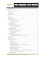
File Name: Project: MEITRACK MVT800 User Guide MVT800 Sub Project: Revision: User Guide V1.5 Creator: Creation Date: Update Date: Page: Confidential: Meitrack 2013-03-03 2013-04-17 1 of 25 External Documentation MEITRACK® GPS Vehicle Tracker User Guide MVT800 Copyright © 2013 Shenzhen Meiligao Electronics Co., Ltd. All rights reserved. 1 File Name: Project: MEITRACK MVT800 User Guide MVT800 Sub Project: Revision: User Guide V1.5 Creator: Creation Date: Update Date: Page: Confidential: Meitrack 2013-03-03 2013-04-17 2 of 25 External Documentation Content 1. Copyright and Disclaimer .................................................................................................................................. 3 2. Applications ...................................................................................................................................................... 3 3. Product Function and Specifications................................................................................................................. 3 3.1 Product Function .......................................................................................................................................... 3 3.2 Specifications ............................................................................................................................................... 4 4. MVT800 and Accessories .................................................................................................................................. 5 5. View .................................................................................................................................................................. 6 6. First Use ............................................................................................................................................................ 6 6.1 Install SIM Card ............................................................................................................................................ 6 6.2 LED Indications ............................................................................................................................................. 7 6.3 Configure by Computer ................................................................................................................................ 7 6.3.1 Set Function Phone Number ............................................................................................................. 9 6.3.2 Set GPRS Parameters ....................................................................................................................... 10 6.4 Protocol Selection ...................................................................................................................................... 11 6.5 Meitrack Protocol Series ............................................................................................................................ 12 6.5.1 Real-time Tracking by Mobile Phone ............................................................................................... 12 6.5.2 Set Function Phone Numbers .......................................................................................................... 13 6.5.3 Arming/Disarming ........................................................................................................................... 14 6.6 Meiligao Protocol Series ............................................................................................................................. 15 6.6.1 Real-time Tracking by Mobile Phone ............................................................................................... 15 6.6.2 Set Function Phone Numbers .......................................................................................................... 16 6.6.3 Arming/Disarming ........................................................................................................................... 16 6.7 Advanced Settings ...................................................................................................................................... 16 6.7.1 Vehicle Transfer Coefficient Function .............................................................................................. 16 6.7.2 RF Match Wireless Remote Control and Vehicle (Optional) ............................................................ 17 6.8 GPS Tracking System................................................................................................................................... 18 7. Installation ........................................................................................................................................................... 20 7.1 Connect GPS/GSM Antennas...................................................................................................................... 20 7.2 Install I/O Cable .......................................................................................................................................... 21 7.2.1 The Definition of I/O Cable .............................................................................................................. 21 7.2.2 I/O Photos ....................................................................................................................................... 22 7.2.3 Power Cable/Ground Wire .............................................................................................................. 22 7.2.4 The Detection Port of High Level and Low Level Configuration....................................................... 23 7.2.5 ACC and Door Detection.................................................................................................................. 23 7.2.6 Signal of Vehicle Speed Sensor Detection ....................................................................................... 23 7.2.7 Remote Control Stop Engine ........................................................................................................... 24 7.2.8 Buzzer Alarm (Optional) .................................................................................................................. 24 7.2.9 Detection Port of Temperature and Fuel --- Meitrack Protocol Only (Optional) .............................. 25 7.2.10 Port of Microphone and Speaker (Optional) ................................................................................. 25 7.3 Mount the MVT800 Unit ............................................................................................................................ 25 Copyright © 2013 Shenzhen Meiligao Electronics Co., Ltd. All rights reserved. 2 File Name: Project: MEITRACK MVT800 User Guide MVT800 Sub Project: Revision: User Guide V1.5 Creator: Creation Date: Update Date: Page: Confidential: Meitrack 2013-03-03 2013-04-17 3 of 25 External Documentation 1. Copyright and Disclaimer Copyright © 2013 MEITRACK. All rights reserve MEITRACK and are trademarks that belong to Shenzhen Meiligao Electronics Co., Ltd. The user manual may be changed without prior notification. This user manual, or any part thereof, may not be reproduced for any purpose whatsoever without the written authorization of Meiligao (MEITRACK), or transmitted in any form, either electronically or mechanically, including photocopying and recording. In no event shall Meiligao (MEITRACK) be liable for direct, indirect, special, incidental, or consequential damages (including but not limited to economic loss, personal injury, and loss of asset and property) arising out of the use or inability or illegality to use the product or documentation. 2. Applications Vehicle Real Time Tracking and Security Fleet Management 3. Product Function and Specifications 3.1 Product Function U-blox 6 GPS and Quad Band GSM 850/900/1800/1900Mhz GPS + GSM Dual Module Tracking SMS/TCP/UDP Waterproof IP65 Track on Demand Track by Time/ Distance Interval Track on Mobile Phone Listen-in or Two-way Audio (Optional) Internal Flash Memory (8M) Inbuilt Motion Sensor Internal Backup Battery 850mAh SOS Alarm Geo-fence Alarm GPS Blind Area Alarm Low Battery Alarm Speeding Alarm Tow Alarm GPS Antenna/ External Power Cut Alarm (MEITRACK and Meiligao Protocol compatible) Copyright © 2013 Shenzhen Meiligao Electronics Co., Ltd. All rights reserved. 3 File Name: Project: MEITRACK MVT800 User Guide MVT800 Sub Project: Revision: User Guide V1.5 Creator: Creation Date: Update Date: Page: Confidential: Meitrack 2013-03-03 2013-04-17 4 of 25 External Documentation Mileage Report Engine Cut (Engine immobilization) 4 Digital Input(1 Negative,1 Positive and 2 can be set through software) 2 Output 1 Analog Input for Fuel Detection (Optional) 1 Input for Pulse Speed Detection 1 Output for Buzzer Alarm (Optional) 1 Input for Digital Temperature Sensor (Optional) Wireless Remote Control (Arming, Disarming, SOS, Looking for Car in Garage) (Optional) 3.2 Specifications Items Specifications Dimension 90*65*32mm Weight 220g Input Voltage DC 11V~36V/1.5A Back-up Battery 850mAh/3.7V Power consumption 85mA standby current Operating Temperature -20℃~55℃ Humidity 5%~95% Work Time 36 hours in power-saving mode and 8 hours in normal mode LED 2 LED lights to show GPS, GSM status Button 1 SOS and 1 power on/off Microphone External connection (Optional) Memory 8M Byte Sensor Motion sensor GSM Frequency GSM 850/900/1800/1900MHz GPS Chip Latest GPS U-blox chipset, 50 channels all-in-view tracking GPS Sensitivity -161dB Positioning Accuracy 10 meters GSM/GPS Antenna SMA external connection antenna I/O 4Digital Input(1 SOS, 1 Positive,1 Door Trigger, 1 ACC Detection) 1 Pulse Speed Detection 2 Output(1 Buzzer Alarm,1 Remote Engine Cut) 1 Analog Input 1 Input for Digital Temperature Sensor 1 USB232 Interface 1Wireless Remote Control (433Mhz) Copyright © 2013 Shenzhen Meiligao Electronics Co., Ltd. All rights reserved. 4 File Name: Project: MEITRACK MVT800 User Guide MVT800 Sub Project: Revision: User Guide V1.5 Creator: Creation Date: Update Date: Page: Confidential: Meitrack 2013-03-03 2013-04-17 5 of 25 External Documentation 4. MVT800 and Accessories MVT800 with Battery GPS Antenna GSM Antenna I/O Cable Power Extension Cord SOS Button USB Data Cable CD Optional Accessories: Wireless Buzzer Alarm Microphone Speaker Remote Control Fuel Sensor Temperature Sensor Copyright © 2013 Shenzhen Meiligao Electronics Co., Ltd. All rights reserved. 5 File Name: Project: MEITRACK MVT800 User Guide MVT800 Sub Project: Revision: User Guide V1.5 Creator: Creation Date: Update Date: Page: Confidential: Meitrack 2013-03-03 2013-04-17 6 of 25 External Documentation 5. View GSM Antenna (Sliver) GPS Antenna (Gold) Power and Functional Cables GSM LED (Green) GPS LED (Blue) On/Off 6. First Use 6.1 Install SIM Card Check that the SIM has not run out of credit (Verify the SIM card has sufficient fund and fully function in a phone); Check the SIM Lock code feature is off; If MVT800 required to send SMS to a function phone number, make sure the Caller ID is not block. Before installing the SIM card, make sure the MVT800 is power off. Unscrew and remove cover of MVT800. Insert the SIM card by sliding it into the card holder with the chip module facing to the connectors on PCB. Put the cover and screws back in place. Copyright © 2013 Shenzhen Meiligao Electronics Co., Ltd. All rights reserved. 6 File Name: Project: MEITRACK MVT800 User Guide MVT800 Sub Project: Revision: User Guide V1.5 Creator: Creation Date: Update Date: Page: Confidential: Meitrack 2013-03-03 2013-04-17 7 of 25 External Documentation 6.2 LED Indications GSM LED (Green) GPS LED (Blue) Press and hold the Power On/Off button for 3~5 seconds to turn on/off MVT800. GPS LED (Blue) On One button is pressed or input is active. Flashing ( every 0.1 second) Initializing or back-up battery power is low Flashing (0.1 second on and 2.9 seconds off) MVT800 has a GPS fix Flashing (1 second on and 2 seconds off) MVT800 has no GPS fix GSM LED (Green) On A call is coming in / a call is being made Flashing ( every 0.1 second) Initializing Flashing (0.1 second on and 2.9 seconds off) MVT800 is connected to the GSM network Flashing (1 second on and 2 seconds off) MVT800 is not connected to the GSM network 6.3 Configure by Computer The following shows you how to configure the MVT800 with MEITRACK Manager. Please refer to the MEITRACK Manager User Guide for more detailed on configurations and functions. For the first time use of USB-to-serial cable, it is required to install the PL2303 Driver Connect the USB Data Cable between MVT800 and PC. Copyright © 2013 Shenzhen Meiligao Electronics Co., Ltd. All rights reserved. 7 File Name: Project: MEITRACK MVT800 User Guide MVT800 Sub Project: Revision: User Guide V1.5 Creator: Creation Date: Update Date: Page: Confidential: Meitrack 2013-03-03 2013-04-17 8 of 25 External Documentation Meitrack Manager will automatically detect port and model, and enter into the main interface as follow: Copyright © 2013 Shenzhen Meiligao Electronics Co., Ltd. All rights reserved. 8 File Name: Project: MEITRACK MVT800 User Guide MVT800 Sub Project: Revision: User Guide V1.5 Creator: Creation Date: Update Date: Page: Confidential: Meitrack 2013-03-03 2013-04-17 9 of 25 External Documentation 6.3.1 Set Function Phone Number Select SMS Tracking to set SMS Tracking, Function Phone Number, Listening-in (Voice Monitoring) and Time Zone, etc. Please refer to the MEITRACK Manager User Guide for more detailed information regarding configuration and functions. Copyright © 2013 Shenzhen Meiligao Electronics Co., Ltd. All rights reserved. 9 File Name: Project: MEITRACK MVT800 User Guide MVT800 Sub Project: Revision: User Guide V1.5 Creator: Creation Date: Update Date: Page: Confidential: Meitrack 2013-03-03 2013-04-17 10 of 25 External Documentation 6.3.2 Set GPRS Parameters Select the GPRS tab to set GPRS parameters, such as Server IP, and Port (IP/Domain: 67.203.13.26, Port: 8800), APN, Time Interval, and GPRS Event Report, etc Please refer to the MEITRACK Manager User Guide for more detailed information regarding configuration and functions. Note: Meitrack Manager software can be found in the enclosed CD. The Language will be chosen automatically according to the user operating system or press Ctrl + L to change the language. Copyright © 2013 Shenzhen Meiligao Electronics Co., Ltd. All rights reserved. 10 File Name: Project: MEITRACK MVT800 User Guide MVT800 Sub Project: Revision: User Guide V1.5 Creator: Creation Date: Update Date: Page: Confidential: Meitrack 2013-03-03 2013-04-17 11 of 25 External Documentation 6.4 Protocol Selection Notice: please don’t switch the protocol to Meiligao if necessary, or some functions may not work via the same command. MVT800 is compatible with both Meitrack and Meiligao Protocol (Default: Meitrack Protocol). Please set through Meitrack Manager. Steps: Connect MVT800 with Personal Computer, click Meitrack Manager.exe, enter the main interface and click Switch to Meiligao Protocol to change the default Meitrack Protocol to Meiligao Protocol. Copyright © 2013 Shenzhen Meiligao Electronics Co., Ltd. All rights reserved. 11 File Name: Project: MEITRACK MVT800 User Guide MVT800 Sub Project: Revision: User Guide V1.5 Creator: Creation Date: Update Date: Page: Confidential: Meitrack 2013-03-03 2013-04-17 12 of 25 External Documentation 6.5 Meitrack Protocol Series 6.5.1 Real-time Tracking by Mobile Phone Make a call to MVT800 and it will report with one SMS. Click on the link then the location can be shown directly on Google Maps on your mobile phone. Report description: Now,110727 02:48,V,16,23Km/h,61%,http://maps.google.com/maps?f=q&hl=en&q=22.540103,114.082329 &ie=UTF8&z=16&iwloc=addr&om=1 Content Description Note Now Current Location Alarm Type 110721 16:40 Date & Time: 21 July, 2011, 16:40pm Date & Time in YYMMDD HH:MM V No GPS fixed GPS Status Indicator: A = valid, V = invalid 10 GSM signal=10 GSM Signal. Decimal Digit (0~31) 0Km/h Speed=0 KM/h. Decimal digit 97% Battery Power: 97% Battery Power Balance (Percentage) Google Maps Web Link with Latitude and http://maps.google.c om/maps?f=q&hl=en Latitude: 22.513015 Longitude. Click on the link to get the &q=22.540103,114.0 Longitude: 114.057235 location. 82329&ie=UTF8&z=1 6&iwloc=addr&om=1 If your mobile cannot visit HTTP websites, input the latitude and longitude into Google Maps as the following picture shows to get the position: Copyright © 2013 Shenzhen Meiligao Electronics Co., Ltd. All rights reserved. 12 File Name: Project: MEITRACK MVT800 User Guide MVT800 Sub Project: Revision: User Guide V1.5 Creator: Creation Date: Update Date: Page: Confidential: Meitrack 2013-03-03 2013-04-17 13 of 25 External Documentation More SMS Commands You can configure MVT800 by mobile phone or by personal computer using the MEITRACK Manager. Please refer to the following text. Note: 1. The default password is 0000, it can be modified through SMS command (Refer to below text) and Meitrack Manager via personal computer (Refer to 6.3 Configure by Computer). 2. MVT800 will only accept commands from a user with the correct password and report SMS report to the user. If function phone number was set, only this phone number can receive SMS reports. 6.5.2 Set Function Phone Numbers Command: 0000, A71,function phone number 1,function phone number 2,function phone number 3 SMS Get: IMEI, A71, OK Note: Function Phone Number: Max 16 characters. If no preset phone number, it is empty (default is empty). First Function Phone Number: Authorize for SOS Alarm, Calling for Real-time Location, Geo-fence Alarm, Low Battery Alarm, Open the Vehicle’s Door or Start the Vehicle without permission. Send command “0000, A71” to delete all function phone numbers. When the SOS button is pressed, MVT800 will make a call to the function phone number 1, 2 and 3. It will stop calling when one number answers. Example: 0000,A71,13811111111,13822222222,13833333333 SMS Get: 353358017784062,A71,OK Copyright © 2013 Shenzhen Meiligao Electronics Co., Ltd. All rights reserved. 13 File Name: Project: MEITRACK MVT800 User Guide MVT800 Sub Project: Revision: User Guide V1.5 Creator: Creation Date: Update Date: Page: Confidential: Meitrack 2013-03-03 2013-04-17 14 of 25 External Documentation 6.5.3 Arming/Disarming There are two ways to set Arming, either through Wireless Remote control (Optional), or SMS Command Suggestion: Using the optional accessory Wireless Remote Control and Buzzer Alarm to strengthen protection, and please set the Function Phone Number to make sure it can be received the call and SMS Report while stolen. Wireless Remote Control: Press the Lock key to Arm. If buzzer alarm installed, it will sound to confirm the Arming successfully, else if buzzer is not available, then open the vehicle’s door to trigger a SMS alert or a call to be sent to the function phone number. Press Unlock to Disarm. SMS Command: Arming and Disarming by SMS Command. Command: 0000,B21,Status SMS Get: IMEI,B21,OK Note: Status=1 Arming, Status=0 Disarming. While in Armed status, and as been triggered by open door or engine starts; MVT800 will call or send SMS report to the function phone number. In the status of Disarm, all security alarms will be OFF. Function Call SMS Engine Cut Buzzer While open the vehicle’s door without permission, the Open the Vehicle’s Note √ √ √ Door buzzer will alarm all the time until unlock the status; MVT800 will send call in turns and send SMS report to the function phone numbers. While start the vehicle, the engine will be cut to avoid Start the Vehicle √ √ √ √ stolen, buzzer will alarm all the time until unlock the status; MVT800 will send call in turns and send SMS report to the function phone numbers. Set Arming While the vehicle was stolen, arming (the arming would while Driving work only setting by SMS or GPRS while driving) and it √ (Intercept √ can be stopped engine to intercept if the speed is lower the Driving than 5km/h. MVT800 will send Alarm SMS report to Vehicle ) function phone numbers. On the status of ACC off, the tow alarm will be trigger Tow Alarm √ √ while the vehicle vibrate.MVT800 will send call in turns and send SMS report to the function phone numbers. Please refer to the MEITRACK SMS Protocol for more detailed SMS command. Copyright © 2013 Shenzhen Meiligao Electronics Co., Ltd. All rights reserved. 14 File Name: Project: MEITRACK MVT800 User Guide MVT800 Sub Project: Revision: User Guide V1.5 Creator: Creation Date: Update Date: Page: Confidential: Meitrack 2013-03-03 2013-04-17 15 of 25 External Documentation 6.6 Meiligao Protocol Series 6.6.1 Real-time Tracking by Mobile Phone Method I: Make a call to MVT800 and it will report with one SMS. Latitude = 22 32 36.63N Longitude = 114 04 57.37E, Speed = 2.6854Km/h, 2008-12-24,01:50 Location Online Checking: Visit http://maps.google.com and enter the Latitude and Longitude to get the location: Method II: SMS Command (Get a map link ) Command: W000000,100 SMS Get: http://maps.google.com/maps?f=q&hl=en&q=22.540103,114.082329&ie=UTF8&z=16&iwloc=addr&om=1 Note: The first value 22.540103 is Latitude, the second value 114.082329 is Longitude. Click on the link then the location can be shown directly on Google Map on your mobile phone. Note: Only smart phones and PDAs support this function. Example: W000000,100 Copyright © 2013 Shenzhen Meiligao Electronics Co., Ltd. All rights reserved. 15 File Name: Project: MEITRACK MVT800 User Guide MVT800 Sub Project: Revision: User Guide V1.5 Creator: Creation Date: Update Date: Page: Confidential: Meitrack 2013-03-03 2013-04-17 16 of 25 External Documentation 6.6.2 Set Function Phone Numbers Command: W******,003,F,P,T Description: Function Phone Number are to receive calls and SMS reports of SOS Alarms, the Alarm and Location of Input 2/Input 3, and Open the Vehicle’s door or Start the Vehicle without permission. Note: F=0, Off (Default) F=1, Send SMS report only F=2, Send SMS report and Call P=1, Set SOS function phone number (Input 1), default to be the number receiving the alarm while open the Vehicle’s door or start the Vehicle without permission. P=2, Set the function phone number of Input2 P=3, Set the function phone number of Input3 T: Default Function Phone Number, Max 16 characters. Example: W000000,003,1,1,88888888 Please refer to the Meiligao Protocol for more detailed SMS command. 6.6.3 Arming/Disarming The same method of Meitrack Protocol, please refer to 6.5.3 Arming/Disarming 6.7 Advanced Settings 6.7.1 Vehicle Transfer Coefficient Function Please connect digital input 5 to vehicle speed sensor then the vehicle’s speed can be calibrated by setting Vehicle Transfer Coefficient. It will be calculated by the latest transfer coefficient after calibration successfully. Two methods: 1. Calibrate Automatically: GPS Speed will be calibrated automatically by transfer coefficient 1) Vehicle has been driving for 60s by the speed beyond 40km/h sequentially. 2) MVT800 has recorded the pulse numbers of sensor in 60s. 3) No sound prompt 4) It won’t be calibrated if there is no pulse. Copyright © 2013 Shenzhen Meiligao Electronics Co., Ltd. All rights reserved. 16 File Name: Project: MEITRACK MVT800 User Guide MVT800 Sub Project: Revision: User Guide V1.5 Creator: Creation Date: Update Date: Page: Confidential: Meitrack 2013-03-03 2013-04-17 17 of 25 External Documentation 2. Calibrate Manually: GPS Speed will be calibrated by setting manually. 1) Send SMS/GPRS Command B23 to enter the status of calibration. The buzzer will make a long sound and the green light on. SMS Command: 0000,B23,Status Description: Status=1, entering calibration; the SMS Command is: 0000,B23,1 Status=2, exit calibration Get: 0000,B23,OK 2) After the Vehicle drives at the speed of 40km/h, press SOS for 2s, MVT800 starts to count the numbers of pulse; after calibrating successfully, the buzzer will make 2 sounds and the green light recover to the normal status. 3) Save the calibrate value after successfully, it will no long to count by GPS speed. 4) Without press SOS after on the status of calibration, the calibration will exit automatically. Note: What is Vehicle Transfer Coefficient? 1) The numbers of the pulse output by vehicle speed sensor for every km, unit: pls/km. 2) Calculate by the formula of Transfer Coefficient: Speed =pls_num*3600/K Speed is the value after calculation, unit km/h Pls_num is the numbers of pulse output by vehicle speed sensor in 1 second K is the transfer coefficient, unit: pls/km 6.7.2 RF Match Wireless Remote Control and Vehicle (Optional) If the wireless remote control doesn’t match with MVT800, please match the code manually. To get the status of the matching, please install buzzer alarm when matching the code. There are 2 methods: 1. Match by ACC Note: If connected Input 4 with ACC, please match follow the steps as below: 1) Turn ACC OFF to ACC ON for 8 times, on the 8th times stay at ACC ON. 2) Wait for 3 seconds, the buzzer will make a long sound entering the matching status, and the green light of the wireless remote control on at the same time. 3) In the status of matching, please press any key of the wireless remote control which is under code matching in 20 seconds. The buzzer will make two sounds to prompt matching successfully. If continue to matching a second wireless remote control, please press any key within this 20 seconds. The buzzer will make two sounds to prompt matching successfully and 5 sounds to exit the matching. 4) Only matching for one wireless remote control, if no any operation when successfully matching code, it will exit automatically after 20 seconds. And the buzzer will make 5 sounds. Note: The times of turn ACC ON to OFF will be cleaned if the time internal beyond 3s in one turns. Please complete code match within 20 seconds, or it will exit automatically. If pressing for a second time on the same wireless remote control, it will exit at once. Copyright © 2013 Shenzhen Meiligao Electronics Co., Ltd. All rights reserved. 17 File Name: Project: MEITRACK MVT800 User Guide MVT800 Sub Project: Revision: User Guide V1.5 Creator: Creation Date: Update Date: Page: Confidential: Meitrack 2013-03-03 2013-04-17 18 of 25 External Documentation 2. Match by SMS Command: 1) SMS Command: 0000,B24,Status Description: Status=1, entering matching; the SMS command is 0000,B24,1 Status=0, exit matching Get: 0000,B24,OK 2) After enter into the status of matching, please refer to the above steps. 3. Key on RF Wireless Remote Control 1 2 3 4 1) Key-1: Short press to arming, the buzzer will make a sound. 2) Key-2: Short press to disarming, the buzzer will make 2 sound. 3) Key-3: Long press for 2s (SOS button function), receive SMS/GPRS alarm. While call the function phone number it will enter into sound off listen-in, the buzzer and speaker won’t sound. 4) Key-4: Looking for vehicle in the garage, short press and the buzzer will make 5 sounds. Note: for more detail information Arming Status, please refer to 6.5.3 Arming/Disarming. 6.8 GPS Tracking System Steps: Configure Parameters -Log in Meitrack Family GPS Tracking System MS02 (www.trackingmate.com) - Add Devices 1. There 2 methods to configure: Configure by SMS: Send SMS command (0000,A21,1,IP,Port,APN,APN username,APN password) and (0000,A12,6,0) to MVT800. Configure by Meitrack Manager: connect with personal computer, run Meitrack Manager.exe, enter the main interface and select GPRS Tracking, setting Server IP, Port, APN, Turn on TCP and Time Internal. Copyright © 2013 Shenzhen Meiligao Electronics Co., Ltd. All rights reserved. 18 File Name: Project: MEITRACK MVT800 User Guide MVT800 Sub Project: Revision: User Guide V1.5 Creator: Creation Date: Update Date: Page: Confidential: Meitrack 2013-03-03 2013-04-17 19 of 25 External Documentation 2. Visit and log in ms02.trackingmate.com (Please contact us if lost your account and password) 3. Enter the map and click Manage -Admin 4. Select Users and add the new device. 5. Get IMEI from serial port and register via IMEI (The IMEI is 011691003108431 for example) Copyright © 2013 Shenzhen Meiligao Electronics Co., Ltd. All rights reserved. 19 File Name: Project: MEITRACK MVT800 User Guide MVT800 Sub Project: Revision: User Guide V1.5 Creator: Creation Date: Update Date: Page: Confidential: Meitrack 2013-03-03 2013-04-17 20 of 25 External Documentation 6. Double click the Control Panel on the right of the main interface to check if the data on the bottom is updated. 7. Installation 7.1 Connect GPS/GSM Antennas GSM Antenna GPS Antenna Connect the GSM antenna to the SMA connector which is ‘GSM’ text labeled. The GSM antenna is non-directional, so you can hide it in any place of vehicle. Connect GPS antenna to the GPS connector which is ‘GPS’ labeled. The optimum location for the GPS antenna is on the roof of the vehicle. The covert and GPS antenna are directional, make sure they are facing up and lying as flat as possible. Secure them in place with glue or zip ties. Note: Do not shield or cover the GPS antenna with any objects containing metal. Copyright © 2013 Shenzhen Meiligao Electronics Co., Ltd. All rights reserved. 20 File Name: Project: MEITRACK MVT800 User Guide MVT800 Sub Project: Revision: User Guide V1.5 Creator: Creation Date: Update Date: Page: Confidential: Meitrack 2013-03-03 2013-04-17 21 of 25 External Documentation 7.2 Install I/O Cable 7.2.1 The Definition of I/O Cable The I/O cable includes power, analog input, negative/positive input and output. I/O Color Description Digital Input 1 (SOS) Input: White Alarm while input1 triggering (Or press SOS). Ground Wire: Black Digital Input 2 White Input2 is available for high level and low level, default is low level, normal output. Digital Input 3(Door) Grey Input3 is available for high level and low level, default is low level for detecting door. Digital Input 4(ACC) Brown High level input (3~60V), default for ACC detection. Digital Input 5(RPM) Green Detect the signal cable of vehicle speed sensor for detecting speed. Digital Output Yellow Open-Drain Output, the power circuit of output is 1W, 0~100V. Ground Wire Black Reserved, work with input/output Power Positive of Power: Red Main Power of the device, DC 11~36V, hardware under-voltage, Ground Wire: Black overvoltage protection Output: Brown PWM Output: Press buzzer, nothing to do with positive and Output: White negative Fuel Capacity AD Positive of Power: Red 0~5V AD detection Detection Port Ground Wire: Black Output positive power is the input voltage of the device (Only for AD Cable: Blue Meitrack Protocol) Buzzer Output The interface should match the fuel sensor Temperature Positive of Power: Red The positive of the power is the output voltage of the device 5V. Detection Port Ground Wire: Black The interface should match the temperature sensor. (Only for USB Cable: Green Meitrack Protocol) Black and Red Black is speaker Microphone and Speaker Remote Control Red is microphone Blue Antenna Copyright © 2013 Shenzhen Meiligao Electronics Co., Ltd. All rights reserved. 21 File Name: Project: MEITRACK MVT800 User Guide MVT800 Sub Project: Revision: User Guide V1.5 Creator: Creation Date: Update Date: Page: Confidential: Meitrack 2013-03-03 2013-04-17 22 of 25 External Documentation 7.2.2 I/O Photos Digital Input 1 (SOS) PWM Output Temperature Detection Remote Control Antenna Fuel Detection Digital Input/ Output Port Microphone and Speaker Port Power Port USB 232 Port 7.2.3 Power Cable/Ground Wire Connect GND (-Black) and Power (+Red) wires to the battery of vehicle. Copyright © 2013 Shenzhen Meiligao Electronics Co., Ltd. All rights reserved. 22 File Name: Project: MEITRACK MVT800 User Guide MVT800 Sub Project: Revision: User Guide V1.5 Creator: Creation Date: Update Date: Page: Confidential: Meitrack 2013-03-03 2013-04-17 23 of 25 External Documentation 7.2.4 The Detection Port of High Level and Low Level Configuration 7.2.5 ACC and Door Detection 7.2.6 Signal of Vehicle Speed Sensor Detection Copyright © 2013 Shenzhen Meiligao Electronics Co., Ltd. All rights reserved. 23 File Name: Project: MEITRACK MVT800 User Guide MVT800 Sub Project: Revision: User Guide V1.5 Creator: Creation Date: Update Date: Page: Confidential: Meitrack 2013-03-03 2013-04-17 24 of 25 External Documentation 7.2.7 Remote Control Stop Engine 7.2.8 Buzzer Alarm (Optional) Buzzer Output Copyright © 2013 Shenzhen Meiligao Electronics Co., Ltd. All rights reserved. 24 File Name: Project: MEITRACK MVT800 User Guide MVT800 Sub Project: Revision: User Guide V1.5 Creator: Creation Date: Update Date: Page: Confidential: Meitrack 2013-03-03 2013-04-17 25 of 25 External Documentation 7.2.9 Detection Port of Temperature and Fuel --- Meitrack Protocol Only (Optional) 7.2.10 Port of Microphone and Speaker (Optional) 7.3 Mount the MVT800 Unit If mounting required, there are 4 screw holes on the MVT800, 2 along either side that act as fixing points to the vehicle. Please do not hesitate to email us at [email protected] if you have any questions. Copyright © 2013 Shenzhen Meiligao Electronics Co., Ltd. All rights reserved. 25