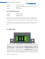
1
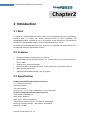
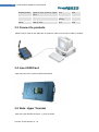
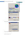
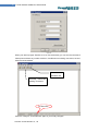
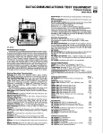
2009 Forwell wireless GPRS DTU Usermanual Gavin Forwell Wireless Co., Ltd. 2009-4-16 2 Forwell wireless GPRS DTU Usermanual V1.10 New Exciting Product D1 Series Cellular DTU User Manual Shenzhen Forwell Wireless Co., Ltd 3 Forwell wireless GPRS DTU Usermanual D1 Series DTU User Manual Shenzhen Forwell Wireless Co., Ltd ADDRESS:2-4A, Chaguang Industrial Park, Nanshan District, Shenzhen, P.R.China Tel: 86-755-26621490 Fax: 86-755-26621490 Web: http://www.forwellwireless.com Shenzhen Forwell Wireless Co., Ltd 4 Forwell wireless GPRS DTU Usermanual Content 1 PROLOGUE ··············································································································································· 6 1.1 VERSION ································································································································· 6 1.2 REFERENCED DOCUMENTS ··········································································································· 6 1.3 NOTICE ··································································································································· 6 2 INTRODUCTION ······································································································································· 7 2.1 BRIEF ····································································································································· 7 2.2 FEATURES ································································································································ 7 2.3 SPECIFICATION ·························································································································· 7 2.4 APPLICATION ···························································································································· 9 3 GETTING STARTED ·································································································································10 3.1 PANEL INTRODUCTION··············································································································· 10 3.2 THE LED STATE ······················································································································· 10 3.3 CONNECT TO PRODUCTS ············································································································ 11 3.4 INSERT SIM CARD ··················································································································· 11 3.5 NOTE: HYPER TERMINAL ··········································································································· 11 3.6 TEST COMMAND ······················································································································ 15 4 CONFIGURE DTU BY PC ·························································································································16 4.1 TCP CLIENT ··························································································································· 16 4.1.1 SerialNet Mode ······················································································ 16 4.1.2 SerialNet Mode with trigger up ······························································· 16 4.1.3 Socket mode ·························································································· 17 4.2 UDP CONNECT ······················································································································· 17 4.2.1 SerialNet Mode ······················································································ 17 4.2.2 SerialNet Mode with Trigger Up ······························································ 18 4.2.3 Socket Mode ·························································································· 18 4.3 DTU POINT TO POINT CONNECTING MODE ··················································································· 18 5 4.3.1 TCP Server ···························································································· 18 4.3.2 UDP Server···························································································· 19 COMOM FUNCTION ······························································································································20 5.1 PING FUNCTION ······················································································································ 20 5.1.1 Common China Unicom DNS ································································· 20 5.2 HOW TO CHANGE BAUD RATE····································································································· 20 5.2.1 Change CDMA Module Baud Rate ························································· 20 5.2.2 Change TCP/IP Module Baud Rate ························································ 21 5.2.3 The relation with parameter to baud rate ················································ 21 5.3 HOW TO SETUP APN OR VPDN ································································································· 21 5.3.1 Setting APN Configuration ······································································ 21 5.3.2 Setting VPDN configuration ···································································· 21 5.4 AT+ITUP FUNCTION ················································································································ 22 5.5 WATCH DOG ·························································································································· 22 5.6 FLOW MONITOR······················································································································ 23 6 DTU COMMUNICATION GUIDE ············································································································24 Shenzhen Forwell Wireless Co., Ltd 5 Forwell wireless GPRS DTU Usermanual 6.1 SOCKET COMMUNICATION ································································································· 24 6.1.1 Environment requests ············································································ 24 6.1.2 Basic setting ·························································································· 24 6.1.3 SOCKET Setting ···················································································· 25 6.2 SERIALNET MODE COMMUNICATION ··························································································· 25 7 6.2.1 Description ····························································································· 25 6.2.2 Environment Requests ··········································································· 26 6.2.3 Basic setting ·························································································· 26 6.2.4 Initialization setting ················································································· 26 PRODUCTION LIST ·································································································································28 Shenzhen Forwell Wireless Co., Ltd 6 Forwell wireless GPRS DTU Usermanual Chapter1 1 Prologue This document is just suit for the following mode type; it helps you quickly to used D1 DTU function and resolves some common questions. Type Description D12S211 GPRS DTU D12Z111 GPRS DTU D12H111 GPRS DTU D13Z311 CDMA DTU D13Z811 CDMA DTU D13H221 CDMA DTU 1.1 Version Version Date Description Author 1.00 2008-08-27 Nearly complete Gavin 1.10 2009-04-16 Format upgrade Gavin 1.2 Referenced Documents D12_Datasheet_Eng D12_QuickStart_Eng D13_Datasheet_Eng D13_QuickStart_Eng 1.3 Notice Forwell Wireless is a registered trademark of Shenzhen Forwell Wireless Co., Ltd. The copyright of the document belongs to Shenzhen Forwell Wireless Co., Ltd. Copying of this document and modifying it and the use or communication of the contents thereof, is forbidden without express authority. Offenders are liable to the legal sanction. Shenzhen Forwell Wireless Co., Ltd 7 Forwell wireless GPRS DTU Usermanual Chapter2 2 Introduction 2.1 Brief D1 Serials is a GPRS/CDMA DTU with TCP/IP Protocol embedded. It has two comparatively individual parts : IP module with TCP/IP, software interface is AT+I commands; and GPRS/CDMA module, supports all the AT Commands. All the standard AT Commands are transferred to GPRS/CDMA module via the transparent Mode of IP module. D1 Serials is usually applicable to the Host, which has no TCP/IP but has serial interface, such as SCM Data Collection Transmission System. 2.2 Features Compact and easy to integrate into your solution; Multi-flexible and compact data interface, TTL, 232 and 485, TTL and 232 are reduced to Rx, Tx, GND; Supports more IP Protocol families; Data transmission via Serial NET Mode, enters transmission mode when power on; Multi-operating status LED; Optimized modularization design, easy to upgrade. 2.3 Specification D12S211& D12Z111& D12H111 Radio Frequency 采用 GSM phase 2/2+标准 GSM (EGSM) 900MHz DCS (GSM) 1800MHz Output power: Class 4 (2 W) at EGSM900 Class 1 (1 W) atDCS1800 D13Z311& D13Z811& D13H221 Radio Frequency TIA/EIA-95B, CDMA2000 1X Band class 0: 800MHz Band class 1: (USPCS 1900MHz) Transmitting Frequency Range:824.64MHZ~848.37MHZ Receiving Frequency Range: 869.94MHZ~893.37MHZ。 Sensitivity>-104DB Shenzhen Forwell Wireless Co., Ltd 8 Forwell wireless GPRS DTU Usermanual D12S211 Power consumption: Speech mode:300mA Sleep mode: 3.5mA Power down :50µA GPRS Modem average:360mA D12Z111 Power consumption: Speech mode: 250mA Slepp mode: 4.0mA Power down: 100mA D12H111 Power consumption: Speech mode: 250mA Sleep mode: 3.8mA Power down: 100mA D13Z311 Power consumption: Idle mode: 70mA Data transfer status: 300~400mA D13Z811 Power consumption: Sleep mode: 70mA Idle mode: 5.0mA Data transfer status: 300~400mA D13H221 Power consumption: Speech mode: 250mA Sleep mode: 4.0mA Power down: 100mA Dimension Interface: RS-232/485/TTL DB9 antenna:50ohm/SMA/Female input voltage: 5~25V (9V) Operating voltage of SIM card: 3V/1.8V Max speed rate of CSD: 14.4KBPS Module reset:AT commands Voice decode standards(three kinds of rate): Half-speed (ETS 06.20) Full-speed (ETS 06.10) Enhanced full-speed (ETS06.50/06.60/06.80) Volume: 75*50/72*16mm weight: 200g Environment Ambient temperature: –20oC to +60oC Storage temperature: -30℃~85℃。 humidity: ≤90% Shenzhen Forwell Wireless Co., Ltd 9 Forwell wireless GPRS DTU Usermanual Electromagnetic Compatible Electrostatic Discharge (ESD): 3 classes Radiated, radio-frequency, electromagnetic field immunity test: 3 class 2.4 Application Remote Data Monitor and Control Water, gas and oil flow metering AMR (automatic meter reading) Power station monitoring and control Remote POS (point of sale) terminals Traffic signals monitor and control Fleet management Power distribution network supervision Central heating system supervision Weather station data transmission Hydrologic data acquisition Vending machine Traffic info guidance Parking meter and Taxi Monitor Telecom equipment supervision (Mobile base station, microwave or optical relay station) Shenzhen Forwell Wireless Co., Ltd 10 Forwell wireless GPRS DTU Usermanual Chapter 3 3 Getting Started 3.1 Panel introduction Note:About Hardware description .please according to following file M1_Modem_DTU_Hardware_Description_V600R.doc 3.2 The LED state In order to check the module working state. Our product have three Led, pwr LED is power state, Ring LED is Ring state, Data LED is Data state。 Start-up PWR Ring Data Lights up 3s,flashing 0.5s,wink wink Lights up 0.5s ,lights up0.5s 0.5s Logon network flashing wink flashing Sleep state Lights up 0.5s, wink 0.5s wink wink date Transfer Lights up 0.5s, wink 0.5s wink flashing Shenzhen Forwell Wireless Co., Ltd 11 Forwell wireless GPRS DTU Usermanual No date transfer Lights up 0.5s, wink 0.5s, Lights wink wink Lights up 1s, wink up 1s Voice call Lights up 0.5s, wink 0.5s wink 4s reboot After 5s. wink wink wink 3.3 Connect to products Please connect antenna and cable with our products, make sure, the port is COM1 or COM2? 3.4 Insert SIM Card Open the back cover. Insert into SIM card as follow 3.5 Note: Hyper Terminal Open the HyperTerminal and input *** (any) as follows Shenzhen Forwell Wireless Co., Ltd 12 Forwell wireless GPRS DTU Usermanual Choose a right port The right configuration as following Shenzhen Forwell Wireless Co., Ltd 13 Forwell wireless GPRS DTU Usermanual (图 3-3) When your start-up Hyper Terminal, it is not connected really, you can see the red mark of follow picture without any number .And then, first Disconnect existing connection, second, Click the red arrowhead Second, click “attribute” tab One-step, Disconnect existing connection No baud rate Click the “configure”, and make sure again of you modify configure Shenzhen Forwell Wireless Co., Ltd 14 Forwell wireless GPRS DTU Usermanual (图 3-5) Make sure your modify configure again, click “OK” Then you can see it appeared baud rate on white label, then click the black label to make call Shenzhen Forwell Wireless Co., Ltd 15 Forwell wireless GPRS DTU Usermanual Make call Have show detect Baud provide power supply with our products, you configured the Hyper Terminal successfully 3.6 Test command Test AT command AT<CF> I/OK //Test “at “command //Response ok parameter if successfully connected, you can make sure the module have no malfunction AT+CSQ<CF> +CSQ: **, ## // to check the Signal quality // ** Should be the number between 10 and 31, the signal quality becomes better as the number grows. ## should be is 99, Or you should checking the equipment of antenna or SIM card. Shenzhen Forwell Wireless Co., Ltd 16 Forwell wireless GPRS DTU Usermanual Chapter4 4 Configure DTU by PC 4.1 TCP Client 4.1.1 SerialNet Mode AT+iHSRV= ip : port AT+iTUP=2 AT+iPARS AT+i! SNMD …… …… …… …… …… +++ AT+iTUP=0 AT+iPARS //set the server IP and port //always online mode //parameter save //switch to SerialNet mode //communication //exit SerialNet mode //disable the always online mode, refer chapter 8 for detail // parameter save Note: our test server: 218.108.22.22: 80 it will send 1 “ok” to client per minute 4.1.2 SerialNet Mode with trigger up AT+iHSRV=ip:port AT+iIATO=n AT+iTUP=1 AT+iPARS AT+iSNMD …… …… …… …… …… +++ // set the Server IP and port //n=Integer, the DTU will offline when the connect no data transport in (n) seconds //set it to trigger up mode, refer chapter 8 for detail // parameters save //switch to SerialNet mode //communication //exit SerialNet mode Shenzhen Forwell Wireless Co., Ltd 17 Forwell wireless GPRS DTU Usermanual AT+iTUP=0 AT+iPARS //disable the trigger up function //parameters save Note: our test server: 218.108.22.22: 80 it will send 1 “ok” to client per minute 4.1.3 Socket mode AT+iSTCP:ip,port I/(000) //establish a tcp connection to the IP and port //000 is the Right connection handle I/ERROR(075) I/ERROR(207) //not logon cellular network,please checking Card and Signal quality //logon cellular network,But can’t connecting to TCP server programme,you should to check firewall, IP Port and port listen if collide with them AT+iSSND%:000, n:******* AT+iSRCV: 000 AT+iSCLS: 000 //send a stream(******) to connect 000, length is (n), //receive data from connection 000 //close the connection 000 Note: our test server: 218.108.22.22: 80 it will send 1 “ok” to client per minute 4.2 UDP Connect 4.2.1 SerialNet Mode AT+iSTYP=1 AT+iHSRV=ip:port AT+iLPRT=port AT+iTUP=2 AT+iPARS AT+i!SNMD …… …… …… …… …… +++ AT+iTUP=0 AT+iSTYP=0 AT+iPARS //set UDP mode //set opposite IP and port //set local port for listen //always online //parameters save //switch to SerialNET mode //communication //exit SerialNet mode //disable always online function //restore to tcp mode //parameter save Shenzhen Forwell Wireless Co., Ltd 18 Forwell wireless GPRS DTU Usermanual 4.2.2 SerialNet Mode with Trigger Up AT+iSTYP=1 AT+iHSRV=ip:port AT+iLPRT=port AT+iIATO=n AT+iTUP=1 AT+iPARS AT+i!SNMD …… …… …… …… …… +++ AT+iTUP=0 AT+iSTYP=0 AT+iPARS //set UDP mode //set opposite IP and port //set local port for listen //n=Integer, the DTU will offline when the connect no data transport in (n) seconds //set it to trigger up mode, refer chapter 8 for detail //parameters save //switch to SerialNET mode //communication //exit SerialNet mode //disable always online function //restore to tcp mode //parameter save Note: change to SerialNet mode, the AT command don’t have "!" 4.2.3 Socket Mode AT+iSUCP:ip,port:lport I/(000) AT+iSSND%:000,n:******* AT+iSRCV: 000 AT+iSCLS: 000 //establish a UDP connection by command. Send data to ip&port, receive data from lport //000 is handle of the connection //send a stream (******) to connect 000, length is (n), //receive data from connection 000 //close the connection 000 4.3 DTU Point to Point Connecting Mode Client setting is the same as above, server setting is below Note: in china mainland, the point-to-point transmit ion mode is used to special network: VPDN, 4.3.1 TCP Server AT+iHSRV=”” //clear the parameter Shenzhen Forwell Wireless Co., Ltd 19 Forwell wireless GPRS DTU Usermanual AT+iLPRT=port AT+iTUP=2 AT+iPARS AT+i!SNMD …… …… …… …… …… +++ AT+iTUP=0 AT+iPARS //setting the listen port //always online //parameters save //switch to SerialNET mode //wait for the connection establish //exit SerialNet mode //disable always online function //parameter save Note: TCP Server must use always online function, please put jumper to the pin of watch dog, refer chapter 7 for detail. 4.3.2 UDP Server No especial setting Note: UDP connection both sides is equal, so both sides is used the same settings as before. Shenzhen Forwell Wireless Co., Ltd 20 Forwell wireless GPRS DTU Usermanual Chapter 5 5 Comom function 5.1 Ping Function AT+iPDS1=220.192.32.103 //setting advanced destination for ping AT+iPDS2=220.192.0.130 //setting backup destination for ping, when first destination reply time out AT+iPDS1=www.sina.com AT+iPDS2=www.21cn.com AT+iPGT=10000 AT+iPFR=n AT+iPARS //Setting aim top-priority server,send PING package for cycle, ( you can changed address with others) //setting backup server,in case top-priority servers have pro blem (you can changed address with others) //setting timeout //setting frequency to send ping packet //parameter save Note: The function is only for SerialNET mode, detect whether online by period sending ping packet. Redial up when be detected offline. In Chinese mainland, China Unicom filter the ping packet to Internet, so the user should set the destination to China Unicom’ DNS. 5.1.1 Common China Unicom DNS 220.192.32.103 220.192.0.130 5.2 How to Change Baud Rate D 5.2.1 Change CDMA Module Baud Rate AT+iMCM AT+IPR? //switch to at command mode //query current baud rate Shenzhen Forwell Wireless Co., Ltd 21 Forwell wireless GPRS DTU Usermanual AT+IPR=n //setting a new baud rate Note: n=0/2400/4800/9600/19200/38400/57600/115200 (the factory default value is 9600) 5.2.2 Change TCP/IP Module Baud Rate AT+i AT+iBDRF=n AT+iBDRM=n AT+iSNSI=”n,8,m,1,0” AT+iPARS //switch to AT+I command mode //below AT+I command should take effect after power down and on //m=n,o,e(no parity, odd parity, even parity), the parameters must use low case //parameter save 5.2.3 The relation with parameter to baud rate n=3 n=4 n=5 n=6 n=7 n=8 n=9 2400 4800 9600 19200 38400 57600 115200 Note: AT+IPR change the CDMA Module baud rate, AT+iBDRF, AT+iBDRM is TCP/IP Module baud rate for command mode, AT+iSNSI is TCP/IP Module baud rate for SerialNET. To change baud rate, you must take the right order, firstly CDMA Module, secondary TCP/IP Module 5.3 How to setup APN Or VPDN 5.3.1 Setting APN Configuration AT+iMIS=”at+cgdcont=1,ip,****” //Setting network(APN), fit for D12S211 AT+iUSRN=**** // user name AT+iPWD=*** // password AT+iPARS //save the parameter 5.3.2 Setting VPDN configuration AT+iUSRN=**** AT+iPWD=*** //user name // password Shenzhen Forwell Wireless Co., Ltd 22 Forwell wireless GPRS DTU Usermanual AT+iPPP=1 //Setting network (VPDN) AT+iATH=n //n=1(PAP),2(CHAP) Network certification mode , need to consult for the UN // Save parameter AT+iPARS 5.4 AT+iTUP Function AT+iTUP=0 AT+iTUP=1 AT+iTUP=2 //disable the function //trigger up mode //always online mode Note1: AT+iTUP=2 is for common SerialNET, auto redial up when offline; AT+iTUP=1 is for SerialNET with trigger up, offline when no data transfer in a period (refer chapter 9 for detail), and trigger up by some signal list below: 1 detect data need to transfer in serial port. 2 detect a ring signal, such as the wireless module has been dialed. Note2: When the DTU in the command mode, and AT+iTUP=2, power on, in about 20~30 seconds the DTU should auto dial up, do not respond any command, If you don’t want to wait, press a stream “+”, to abort the DTU operation. 5.5 Watch Dog K1 K2 Monitor Timeout Open Open ∞ Open Close 15 minutes(D22S211/Z111/Z311) 30 minutes(D22h11/C111) Close Open 30 minutes(D22S211/Z111/Z311) 10 minutes(D22h11/C111) close Close RG Close Shenzhen Forwell Wireless Co., Ltd 5 minute GT Close Open 23 Forwell wireless GPRS DTU Usermanual R● Reserve Monitor Host receive Disable the Function G● T● 5.6 Flow Monitor AT+iIATO=n //n>60 (second), offline when no data transfer (both send & receive) in the setting time. Note: In the common SerialNET mode and AT+iTUP=2, the DTU should re-online immediately. In the SerialNET with trigger up and AT+iTUP=1, the DTU should be offline until be trigger up Shenzhen Forwell Wireless Co., Ltd 24 Forwell wireless GPRS DTU Usermanual Chapter 6 6 DTU Communication Guide 6.1 SOCKET Communication D1-DTU has two operating modes, one is Command Mode, and the other is SerialNET Mode. Socket communication is implemented in Command Mode, when operating need commands to be sent. 6.1.1 Environment requests You should be sure about the following test environment before starting the test A computer online as application service center, which should have public network IP address. Assure that the application service center has no programming implementation at gateway, and no restriction to 1024 port. Copy Server.exe (Download from www.forwellwireless.com) and implement in the computer. Setup listening mode (Default one is 1024,user can setup another one according to his own requirement). Get the IP address of the computer. Note:Fit for the requirements, we need to upgrade the software sometimes, the version you download maybe different from the photo above. The photo above is V1.32. 6.1.2 Basic setting AT+IISP1=*99***1# AT+IDNS1=211.136.18.171 AT+IUSRN=WAP AT+IPWD=WAP AT+IMIS="AT+CGDCONT=1,ip,CMNET" //You can get the parameter from your local network distributor. AT+IXRC=0 AT+IMTYP=2 Note:You can omit this procedure if have set before. Shenzhen Forwell Wireless Co., Ltd 25 Forwell wireless GPRS DTU Usermanual 6.1.3 SOCKET Setting The following is an example of setting TCP communication .Default port is 1024, user can setup another one according to his own requirement. AT+ISTCP :xxx .xxx .xxx .xxx,<Port Number> <CR> //Set SOCKET connection ,here xxx .xxx .xxx .xxx means IP address of the computer.<Port Number>means port number ,response I/xxx.xxx means handle number. The center shows the connection and gets the IP address of client if successfully connects. The center will display the detailed information, amount and speed as soon as the client transmits data. Generally, IP address of client will be cancelled by the center automatically once the client disconnects with the center via Socket command. Please note some unexpected situations, the center can’t cancel its IP address if disconnects abnormally(eg. power off), when client connects with the center again, it will shows that there exists two clients though there just one client connect with the center. AT+ISSND%:xxx,<string Length>:<string> <CR> //Transfer data, xxx means handle, <string length> is the string length of The transmission,<string> means the data. You can see the data from the terminal in the center. AT+ISST:xxx<CR> //Check Socket status, xxx means handle. Response I/ <socketstat> If <socketstat>≥0, means the number of the byte in Buffer; if <socketstat><0,means Socket error. AT+ISRCV:xxx<CR> //receive data,xxx means handle. Input characters and then press “ enter”, thus the data is transferred from the center to the terminal. AT+ISCLS:xxx //Close Socket,xxx means handle Please see Socket part of AT+I Command to get detailed information. 6.2 SerialNET Mode Communication 6.2.1 Description D1-DTU has two operating modes, one is Command Mode, and the other is SerialNET Mode. Shenzhen Forwell Wireless Co., Ltd 26 Forwell wireless GPRS DTU Usermanual Socket communication is implemented in Command Mode, when operating need commands to be sent. While in SerialNET Mode, as long as you initialize its parameter, you can transfer data via the parameter directly. That’s because SerialNET Mode helps the equipment connect to D1 set TCP/UDP Socket connection via serial link. 6.2.2 Environment Requests You should be sure about the following test environment before starting the test: A computer online as SerialNET Mode server, which should have public network IP address. Assure that the application service center has no gateway programming implementation, and no restriction to 1024 port Copy Server.exe (Download from www.forwellwireless.com) and implement in the computer. Setup listening mode (Default one is 1024). Get the IP address of the computer. Another machine for communication between SerialNET Client server and server.。 Open the hyper terminal of the client 6.2.3 Basic setting AT+IISP1=*99***1# AT+IDNS1=211.136.18.171 AT+IUSRN=WAP AT+IPWD=WAP AT+IMIS="AT+CGDCONT=1, ip, CMNET" AT+IXRC=0 AT+IMTYP=2 Note: You can omit this procedure if have set before. 6.2.4 Initialization setting Serial NET Mode is established by first defining all related parameters using AT commands. Once in Serial NET Mode, no additional AT commands may be sent, as the host serial link will be dedicated to data, any characters will be sent as data. In this mode, no response for any commands, it’s normal. Shenzhen Forwell Wireless Co., Ltd 27 Forwell wireless GPRS DTU Usermanual AT+IHSRV= xxx.xxx.xxx.xxx:< Port Number> <CR> // Set Serial NET communication server IP, xxx.xxx.xxx.xxx means IP address, or name of the server, but it should be the one which DNS can read. <Port Number> means server listen port. If successfully sets, returns with I/OK. AT+IDSTR=<string > <CR> //Set disconnection signal in SerialNET Mode. <String> means signal string. After the terminal receives the signal string, it will disconnect automatically. <string> may be composed of any characters, unprintable ASCII character can be replaced by /Oxhh, here h mean hex number, 0..9 or A..F, that’s to say hex number represents the character. For example: AT+IDSTR=EEEEE //the terminal will disconnect automatically as soon as it receives “EEEEE” AT+IDSTR=PP\0x31 // the terminal will disconnect automatically as soon as it receives “PP1”string. Returns with I/OK if successfully sets. AT+ISTYP=v <CR> //Set Socket communication type in Serial NET Mode. v=0|1 //0 Means TCP, 1 means UDP Returns with I/OK if successfully sets AT+ISNSI=<baud>, <data_bits>,<parity>,<stop_bits>,<flow> <CR> //Set communication interface parameter in SerialNET Mode. <baud>=3..9 //baud rate classification <data_bits>=7|8 // data bit <parity>=N|E|O //verification <stop_bits>=1 //stop bit <flow>=0|1 //flow control Default value: 8, 8,N, 1,0 //57600bps, 8 bits, doesn’t need verify, one stop bit, doesn’t need flow control. Returns with I/OK if successfully sets. AT+iIATO=n<CR> //Set IATO parameter n=0~65535, 1.2~1.5 heart-break cycle in common. Returns with I/OK if successfully sets. Shenzhen Forwell Wireless Co., Ltd 28 Forwell wireless GPRS DTU Usermanual Chapter 7 7 Production list name unit number description Host Entries 1 Standard supply power Entries 1 Supply 9V antenna Entries 1 Standard supply Production-CD piece 1 Standard supply Shenzhen Forwell Wireless Co., Ltd Sketch-map