1
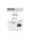
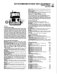
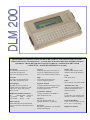
THE DLM 200 IS A VERSATILE AND INTELLIGENT RS-232 DATA ANALYZER. IT MAKE ANALYSES , TIME STAMP EVENTS , ANSWERS BACK… IT COMPARES WITH MUCH BIGGER AND MORE EXPENSIVE EQUIPMENT. THE RS -485 AND /OR WAN OPTION MAKES IT A COMPLETE RS -485 AND /OR V.10/11/35/36 – RS -422/423/449/530-X21 ANALYZER. Line Speeds 75-115.2 kbps Asynchronous 75-64 kbps Synchronous Plus any User Defined speed. Triggers Start, stop, plus auto reset of start on stop on user-defined strings up to 80 bytes or any modem interface pattern. Protocols Asynchronous, Bisynchronous, Sdlc, Hdlc, Isochronous, X.25. Help On line help for all functions, common suggestion library. Autoconfigure Deciphers protocols, bit rates, number of bits per character, synch characters or parity and presents data to screen. Response Analysis Average times between triggers (up to four hours) to measure human and computer performance. Display Type Liquid Crystal Display (LCD) Graphic-8 line by 40 characters Parity Odd, Even, None Codes ASCII, EBCDIC, BAUDOT, IPARS Bit/Block Transmission Patterns 511 RD/TD buffer ASCII set User string1 FOX 00, FF User string2 FOX2 0-FF Buffer capacity 128k-256k split between transmitted Data, received data and modem control history. Performance Analysis Average trip times on any BERT or block transmission test. Interfaces RS-232, parallel printer port optional: RS-485, V.35, RS-422 Keyboard Full 64 key, QWERTY-style keyboard and PC-style keypad. Automatic Power Off After user-specified timeout; or disable auto shutoff for overnight line testing. Power 9-volt battery (10-20 hours with alkaline) or extern. Transformer. Physical (Handheld) 9.25 x 5.5 x 1.37 inches; 23 oun. 23.5 x 13.5 x 3.3 cm; 630 g English user manual THE COMMAND KEYS CLEAR BUFFER Deletes all data in the buffers. END Moves cursor to end of screen or buffer. FORCE CAPTURE Forcing synchronisation forces the DLM to begin capturing all data. This is useful when the synch character is unknown or is not known if a clock signal is present on pins 15&17. All bits will be captured. MENU Toggles between the View Mode and the Configure Menu. PULSE CAPTURE Collects changes to any modem control signals up to 40000 changes. SEARCH RD, SEARCH TD Immediately searches contents of the RD (or TD) capture buffer, looking for a match of string 1. SHIFT ONE BIT RIGHT Shifts all data in the capture buffer one bit to the right. Useful in conjunction with FORCE CAPTURE TEXT/HEX Toggles between displaying data in the current mode (ASCII, etc) and hex code. F1, F2, F3, F4,↑ ↑ , ↓ , ↔ , HOME, PAGE DOWN, PAGE UP All of the F-keys and the cursor-control keys are programmed to serve different functions depending on what screen or menu is on the display. ANSWERBACK Special Terminal mode. String2 automatically transmitted when string1 received. Also transmitted when Page down pushed. BERT/PERFORMANCE TES T Bit Error Rate Testing (BERT) transmits test pattern through a DCE and back to the DLM, which compares the incoming data to the original string, counts and reports errors and trip time. EDIT STRING Drops you into a line editor. From this line editor you can create 1 or 2 80-byte ASCII strings by typing in bytes from keyboard. RESPONSE MONITOR Monitor human or machine response time by using the timer. SET TRIGGER CAPTURE Begins or terminates data collection. STATUS Four separate status screens provide ni formation about the data in the buffer. SUPPRESS CAPTURE Suppress capture of data on 1 or both lines. AUTO TD CONFIG, AUTO RD CONFIG DLM will analyse TD or RD signal and automatically set to match its parameters. EDIT MODEM MASKS CONTROL SIGNAL Create a mask to match a set of modem control signals. Used to start or stop the timer or trigger. EVENTS AND TIME STAMP Keep a log of errors and triggers. COMMUNICATION OPTIONS BAUD RATE 64000* 14400 1243 56000* 9600 1200 48000* 4800 600 57600 2400 300 38400 2000150 19200 1800 USER SELECTABLE * Sync only STOP BITS 1, 1.5, 2 DATA BITS 5, 6, 7, 8. PARITY Even, None, Odd DATA ENCODING NRZ, NRZ1, FM0, FM1 MODE Async, Mono Sync, Bisync, SDLC, Isochronous SYNC CHAR 1 (User-defined, default 16) SYNC CHAR 2 (User-defined, default 16) SDLC NODE All, Node numbers IGN MULTI-SYNC CHR Yes, No DROP SYNC RTS/CD Yes, No DROP SYNC CHAR None, (User-defined) LOG EVENTS No, 1Fill, Cont. CODE ASCII, EBCDIC, IPARS, BAUDOT DISPLAY MODE Compressed, Expanded BUFFER One fill, Continuous STATUS MESSAGES Normal, Long, None, Short HELP Offers assistance on many topics ERROR MESSAGES Fatal, Warn, None AUTO OFF (User-defines – minutes) LOAD CONFIG1, 2 & 3 The DLM 200 allows to save three sets of system communication parameters. EXCLUDE Off, Control data, Text Data, START TXT CHAR (User-defined) END TXT CHAR (User-defined) START/STOP Use to begin & end many activities. SAVE CONFIG The DLM allows to save up to 4 sets of system parameters for quick set-up later. REMOTE BAUD 57.6k, 19.2k, 9.6k, 4.8k, 2400, 1200 TIME EVENTS Used to time events. SET CLOCK Set the internal clock on the DLM 200. INVERT BITS Yes, No VERSION Displays version of firmware installed. TIME Displays current time and date. GOTO LOCATION Moves cursor to a particular buffer location. For example, type in 6 if you want the cursor to be placed on the sixth character in the buffer. Option 2 : The MC-232 makes your DLM an extensive WAN interface analyser ! This option converts RS-232 to V.10/11/35/36, RS-422/423/449/530 and X.21. The MC-232 works in DTE/DCE and monitor mode, and works up to 128kbps. It can also monitor RS-485 interAllows your DLM to monitor RS-422/485. It con- faces. A very complete and compact solution, for a nects directly to the DLM 200 and offers RJ11 and marginal price of a big/heavy dedicated WAN screw terminal connection on the RS422-485 side. analyser. The converter comes complete with 9-volt mains For more information, ask your MC-232 flyer. adapter and user’s manual. OPTIONAL: IC458 RS-232-RS-422/485 converter For further information, please contact : Specifications are subject to change without notice. Copyright 1999. Comcraft, Oberschaeffolsheim, France THE COMMAND KEYS CLEAR BUFFER Deletes all data in the buffers. END Moves cursor to end of screen or buffer. FORCE CAPTURE Forcing synchronisation forces the DLM to begin capturing all data. This is useful when the synch character is unknown or is not known if a clock signal is present on pins 15&17. All bits will be captured. MENU Toggles between the View Mode and the Configure Menu. PULSE CAPTURE Collects changes to any modem control signals up to 40000 changes. SEARCH RD, SEARCH TD Immediately searches contents of the RD (or TD) capture buffer, looking for a match of string 1. SHIFT ONE BIT RIGHT Shifts all data in the capture buffer one bit to the right. Useful in conjunction with FORCE CAPTURE TEXT/HEX Toggles between displaying data in the current mode (ASCII, etc) and hex code. F1, F2, F3, F4,↑ ↑ , ↓ , ↔ , HOME, PAGE DOWN, PAGE UP All of the F-keys and the cursor-control keys are programmed to serve different functions depending on what screen or menu is on the display. ANSWERBACK Special Terminal mode. String2 automatically transmitted when string1 received. Also transmitted when Page down pushed. BERT/PERFORMANCE TES T Bit Error Rate Testing (BERT) transmits test pattern through a DCE and back to the DLM, which compares the incoming data to the original string, counts and reports errors and trip time. EDIT STRING Drops you into a line editor. From this line editor you can create 1 or 2 80-byte ASCII strings by typing in bytes from keyboard. RESPONSE MONITOR Monitor human or machine response time by using the timer. SET TRIGGER CAPTURE Begins or terminates data collection. STATUS Four separate status screens provide ni formation about the data in the buffer. SUPPRESS CAPTURE Suppress capture of data on 1 or both lines. AUTO TD CONFIG, AUTO RD CONFIG DLM will analyse TD or RD signal and automatically set to match its parameters. EDIT MODEM MASKS CONTROL SIGNAL Create a mask to match a set of modem control signals. Used to start or stop the timer or trigger. EVENTS AND TIME STAMP Keep a log of errors and triggers. COMMUNICATION OPTIONS BAUD RATE 64000* 14400 1243 56000* 9600 1200 48000* 4800 600 57600 2400 300 38400 2000150 19200 1800 USER SELECTABLE * Sync only STOP BITS 1, 1.5, 2 DATA BITS 5, 6, 7, 8. PARITY Even, None, Odd DATA ENCODING NRZ, NRZ1, FM0, FM1 MODE Async, Mono Sync, Bisync, SDLC, Isochronous SYNC CHAR 1 (User-defined, default 16) SYNC CHAR 2 (User-defined, default 16) SDLC NODE All, Node numbers IGN MULTI-SYNC CHR Yes, No DROP SYNC RTS/CD Yes, No DROP SYNC CHAR None, (User-defined) LOG EVENTS No, 1Fill, Cont. CODE ASCII, EBCDIC, IPARS, BAUDOT DISPLAY MODE Compressed, Expanded BUFFER One fill, Continuous STATUS MESSAGES Normal, Long, None, Short HELP Offers assistance on many topics ERROR MESSAGES Fatal, Warn, None AUTO OFF (User-defines – minutes) LOAD CONFIG1, 2 & 3 The DLM 200 allows to save three sets of system communication parameters. EXCLUDE Off, Control data, Text Data, START TXT CHAR (User-defined) END TXT CHAR (User-defined) START/STOP Use to begin & end many activities. SAVE CONFIG The DLM allows to save up to 4 sets of system parameters for quick set-up later. REMOTE BAUD 57.6k, 19.2k, 9.6k, 4.8k, 2400, 1200 TIME EVENTS Used to time events. SET CLOCK Set the internal clock on the DLM 200. INVERT BITS Yes, No VERSION Displays version of firmware installed. TIME Displays current time and date. GOTO LOCATION Moves cursor to a particular buffer location. For example, type in 6 if you want the cursor to be placed on the sixth character in the buffer. Option 2 : The MC-232 makes your DLM an extensive WAN interface analyser ! This option converts RS-232 to V.10/11/35/36, RS-422/423/449/530 and X.21. The MC-232 works in DTE/DCE and monitor mode, and works up to 128kbps. It can also monitor RS-485 interAllows your DLM to monitor RS-422/485. It con- faces. A very complete and compact solution, for a nects directly to the DLM 200 and offers RJ11 and marginal price of a big/heavy dedicated WAN screw terminal connection on the RS422-485 side. analyser. The converter comes complete with 9-volt mains For more information, ask your MC-232 flyer. adapter and user’s manual. OPTIONAL: IC458 RS-232-RS-422/485 converter For further information, please contact : Specifications are subject to change without notice. Copyright 1999. Comcraft, Oberschaeffolsheim, France