1
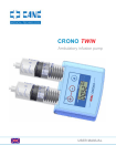
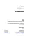
ROMA
INSTRUCTIONS MANUAL
INDEX
1. SAFETY AND WARNING .............................................................................................................................................................................................2
2. DEFINITION ..................................................................................................................................................................................................................3
2.A. ROMA INTERNAL COMPONENTS.....................................................................................................................................................................3
2.B. ROMA CAPPUCCINO INTERNAL COMPONENTS............................................................................................................................................4
3. PARTS IDENTIFICATION.............................................................................................................................................................................................4
3.A. ROMA PARTS IDENTIFICATION ........................................................................................................................................................................5
3.C. ROMA CAPPUCCINO PARTS IDENTIFICATION...............................................................................................................................................5
SECTION “A” – INSTALLATION AND MAINTENANCE......................................................................................................7
4. INSTALLATION AND CONNECTIONS........................................................................................................................................................................8
4.A. HOW TO REMOVE THE MACHINE FROM THE PACKAGE..............................................................................................................................8
4.B. GENERAL INFORMATION ON CONNECTIONS................................................................................................................................................8
4.C. WATER CONNECTION .......................................................................................................................................................................................9
4.D. ELECTRIC CONNECTION...................................................................................................................................................................................9
4.D.1. EQUIPOTENTIAL CONNECTION: ..............................................................................................................................................................9
5. OPERATING PROCEDURES.....................................................................................................................................................................................10
5.A. START UP ..........................................................................................................................................................................................................10
5.B. START UP - VERSION WITH GAS SYSTEM....................................................................................................................................................10
5.C. ADJUSTMENTS .................................................................................................................................................................................................11
6. DIGIT AUTOMATIC VERSION PROGRAMMING ......................................................................................................................................................12
6.A. ROMA DOSES PROGRAMMING ......................................................................................................................................................................12
6.B. ROMA CAPPUCCINO DOSES PROGRAMMING.............................................................................................................................................13
6.C. GROUND COFFEE DOSE PROGRAMMING - ROMA PLUS MODEL .............................................................................................................13
6.D. TRACTABLE WATER LITRES PROGRAMMING - ONLY FOR ROMA PLUS MODEL ..................................................................................13
7. TROUBLESHOOTING AND SOLUTIONS .................................................................................................................................................................14
8. MAINTENANCE ..........................................................................................................................................................................................................16
8.A. BOILER WATER DRAINING - ROMA AND ROMA PLUS MODELS ...............................................................................................................16
8.B. INSTRUCTIONS FOR REGENERATING THE SOFTENER .............................................................................................................................16
SECTION “B” – USER INSTRUCTIONS.............................................................................................................................17
9. BEVERAGES DELIVERY DESCRIPTION .................................................................................................................................................................18
9.A. COFFEE DELIVERY ..........................................................................................................................................................................................18
9.B. HOW TO MAKE CAPPUCCINO ........................................................................................................................................................................19
9.C. STEAM AND WATER DELIVERY ....................................................................................................................................................................19
10. CLEANING................................................................................................................................................................................................................19
10.A. SANITATIONS .................................................................................................................................................................................................19
10.B. DAILY CLEANING PROCEDURES.................................................................................................................................................................20
10.C. WEEKLY CLEANING PROCEDURES ............................................................................................................................................................20
11. DISMANTLING..........................................................................................................................................................................................................21
SECTION “C” - Technical data, Wiring and Hydraulic Diagrams ……………………………..………………….……….. 1
REV.4 01/2007
ENGLISH - 1
1. SAFETY AND WARNING
We, at BRASILIA, are committed to manufacturing safe operating and serviceable equipment. The many built-in safety
features that are part of all BRASILIA equipment are aimed at protecting operators and trained service technicians alike.
• DO NOT operate machine without reading all information given in this manual. Failure to follow this instruction may result in equipment damage, poor machine performance, health hazards, or personal injury. The manual is intended for the machine’s installer and/or
maintenance technician and for the machine's user.
In case of dismay or for further information, contact the local retailer or the manufacturer. This manual reflects the state of the art at the
current time and cannot be considered inadequate merely because it is updated later on the basis of new developments. The manufacturer also reserves the right to modify the manual without the duty of updating earlier issues, except in exceptional cases.
The pictures, in this manual, are just explanatory and they could not reflect the aesthetics of all models described.
• DO NOT operate the machine without complying with all local the safety regulations in force in your country of installation as well as
all the rules dictated by common sense, and ensure that routine maintenance is carried out regularly and correctly.
• DO NOT operate machine unless it is properly grounded. Failure to follow this instruction may result in electrocution.
• DO NOT replace or remove safety instructions and technical data for proper and safe installation and operation, as affixed to machine.
• DO NOT touch the groups, the coffee spouts or the water/steam pipes during the operation of machine (pipes must be handle only
through special hand-grip); the liquids/steam delivered and the machine parts are very hot and could cause burns.
• DO NOT touch the keys during brewing cycle.
• DO NOT try to remove any mechanical parts from machine and NOT perform arbitrary modifications. Contact your local authorized
service agent/technician.
• DO NOT pull electric power cord to disconnect machine from the wall socket.
• DO NOT allow machine to be used by children or incapable persons.
• DO NOT expose machine to outdoor environment (sun, rain, snow, etc.).
• DO NOT operate machine unless all service panels and access door are closed.
• DO NOT insert spoons, forks or any other utensil into the machine if it is switched on.
• DO NOT operate machine without water supply.
• DO NOT obstruct any air intake or exhaust openings: 4” (10 cm) minimum air space behind the machine and 2” (5 cm) space on either side.
• DO use only ground coffee or coffee pods for models with special filter-holder.
• DO use only filtered and treated fresh water, or pure drinking water (Hardness approx. 7 french degrees).
• DO use only original BRASILIA spare parts. Failure to follow this instruction will render any warranty, expressed or implied, or guarantees by manufacturer or authorized service agent ass NULL and VOID.
• Always PERFORM recommended daily and cleaning operations.
• CLEANING:
- DO NOT use water sprayers or pressurized water jets to clean machine.
- DO NOT use detergents containing perfumes, alcohol or ammonia either directly or indirectly (damp cloth) to clean machine.
- USE only disinfecting detergents suitable for crockery.
- Chemical-based detergents used for cleaning machine and/or the system should be used with care so as not to deteriorate any components or cause damage to environment when discarded.
CAUTION: Improper maintenance and cleaning, use of unfiltered water, or damage to internal parts may cause possible blockages in
water flow leading to unexpected jets of hot liquid or steam. This may cause serious injury. Use CAUTION while washing and servicing
machine!
• SANITATIONS:
Coffee and its ingredients (sugar, milk, etc.) are sensitive products and therefore the following basic hygiene processes need to be considered. The following are factors which can affect finished product quality served to the customer:
• Wash hands past elbows. Periodically wash it also throughout the day.
• Wear rubber gloves if cuts or skin conditions exist.
• Clean all parts and components thoroughly.
• Use approved sanitizing tablets.
• Store sanitizer in a cool, dry place. Use in accordance to instructions.
• Allow employee uninterrupted time to complete the cleaning procedure.
• Do not neglect daily cleaning procedures: follow "CLEANING" instructions in the User Manual.
• Rotate stock to use older date product first (FIFO). Observe product expiry date. Product must never be stacked outside or under direct sunlight. Check the indications on the confection.
• ADVISE FOR INSTALLER AND MAINTENANCE TECHNICIAN:
• BRASILIA S.p.A. and maintenance technician decline every responsibility in the following cases:
if the machine is used for any other than its intended purposes, as described in this manual.
if the recommended maintenance and cleaning procedures are NOT performed.
if original BRASILIA spare parts are not used.
if the INSTALLER, or MAINTENANCE TECHNICIAN, it is NOT authorized and specialized.
if, despite the INSTALLER has obviously taken every possible precaution to guarantee user safety, the different installation
and/or transport conditions could give rise to uncontrollable or unpredictable situations.
• Authorized service agent (installer or maintenance technician) must inform original manufacturer of POSSIBLE FAULT or wear
which may affect the machine system’s original safety.
• The appliance must be installed in a place where only authorized personnel could perform its use and maintenance.
• Check the condition of the components and, should defects or faults arise, stop the installation and ask for their replacement.
REV.4 01/2007
ENGLISH - 2
• Regularly perform the MAINTENANCE PROCEDURES. The ENVIRONMENT TEMPERATURE while performing maintenance operations must be at least 5°C and not over 30°C.
• Check that the shelf, on which the machine will come located, is not tilted.
• Place the machine on a shelf high enough to allow the cup warmer to be located at least at 150 cm. over the floor.
• Aerial noise: in the machine operating place the loudness level does not normally overcome 70 dB.
• Do not install the machine in places where jets of water are normally used.
• If the machine is NOT used for a long time, disconnect the cable to the mains line switch and close the water mains tap.
• ADVICES OF USE:
- Always use heated cups: if this is cold, the abrupt temperature change of the espresso coffee will change its taste.
- Never load the filter holder without making an immediate delivery; the ground coffee would “burn” in the group and the espresso obtained would be very bitter.
- Clean regularly the dosing grinder and check the wear of the grindstones.
- The machine’s operating process forces the water over the coffee at high pressure. If contact between the water and the ground coffee lasts more than 20/30 seconds, the coffee will taste unpleasant and bitter. This effect is called over-extraction.
- Ground coffee dose, for ONE espresso, between 6 and 7 g. inclusive.
- Checking the wear of the dosing grinder’s grindstones.
2. DEFINITION
AUTOMATIC MACHINES:
ROMA DIGIT:
- Espresso coffee machine with microprocessor controlled electronic measured dosage.
- Digital programming from the push-button pad.
- Automatic boiler filling is standard.
- Filter for mixed use either with ground coffee or with coffee pod upon request.
- Automatic boiler filling is standard.
ROMA CAPPUCCINO DIGIT:
- Compact espresso coffee machine with incorporated automatic coffee dosing grinder and microprocessor controlled electronic measured dosage.
- Digital programming from the push-button pad.
- Automatic boiler filling is standard.
SEMIAUTOMATIC MACHINES:
ROMA P:
- Semi-automatic espresso coffee machine with continuous delivery.
- Automatic boiler filling upon request.
- Filter for mixed use either with ground coffee or with coffee pod upon request.
ROMA CAPPUCCINO P:
- Semi-automatic espresso coffee machine with continuous delivery.
- Automatic boiler filling upon request.
- Filter for mixed use either with ground coffee or with coffee pod upon request.
2.A. ROMA INTERNAL COMPONENTS
• Boiler: Is used to contain the hot water and steam and is made of copper so that its properties do not deteriorate over the years.
• Brewing group and heat exchanger:
- The brewing group is the component which, when attached to the filter holder (containing the filter and the ground coffee), brews and
delivers the beverages when supplied with hot water.
- The heat exchangers, one for each group, are immersed in the water and are used for fast heating of the fresh water from the network
to the optimal temperature and to prevent thermal imbalances within the system.
• Heat source: This is normally provided by an electric heating element immersed in the boiler and/or by an external gas burner, which
heat the water and provide the steam.
• Rotary pump: This device is used to raise the pressure of the network, which is normally inadequate for the purpose, to a pressure of
0,9 MPa (9 BAR) which is ideal for making the best coffee.
• Steam tap: It allows steam to be delivered to give the indispensable “froth” to the milk used for preparing cappuccino, for heating water and punches and for preparing chocolate drinks.
• Water tap: It allows water to be delivered for preparing hot drinks, tea and tisanes.
• Milk frothing device (Optional): This device is used to "froth" the milk to prepare cappuccino
• Control instruments:
- Manometers: show the current pressure in the boiler and the pump’s operating pressure.
- Pressure switches: control the pressure and the switching on of the heat sources to keep the boiler water temperature constant.
- Level gauge: shows the water level in the boiler.
- Thermostats: allow the temperature adjusting.
- Warning lights: show the boiler filling and the switching on of the heat sources.
REV.4 01/2007
ENGLISH - 3
2.B. ROMA CAPPUCCINO INTERNAL COMPONENTS
• Boiler: Is used to contain the hot water and steam and is made of copper so that its properties do not deteriorate over the years.
• Brewing group and heat exchanger:
- The brewing group is the component which, when attached to the filter holder (containing the filter and the ground coffee), brews and
delivers the beverages when supplied with hot water.
- The heat exchangers, one for each group, are immersed in the water and are used for fast heating of the fresh water from the network
to the optimal temperature and to prevent thermal imbalances within the system.
• Heat source: This is normally provided by an electric heating element immersed in the boiler and/or by an external gas burner, which
heat the water and provide the steam.
• Water pressure held stable by a vibration pump, with an internal safety by-pass system.
• Steam tap: It allows steam to be delivered to give the indispensable “froth” to the milk used for preparing cappuccino, for heating water and punches and for preparing chocolate drinks.
• Water tap: It allows water to be delivered for preparing hot drinks, tea and tisanes.
• Milk frothing device (Optional): This device is used to "froth" the milk to prepare cappuccino
• Control instruments:
- Manometers: show the current pressure in the boiler and the pump’s operating pressure.
- Pressure switches: control the pressure and the switching on of the heat sources to keep the boiler water temperature constant.
- Level gauge: internal buzzer.
- Thermostats: allow the temperature adjusting.
- Warning lights: show the boiler filling and the switching on of the heat sources.
3. PARTS IDENTIFICATION
REV.4 01/2007
ENGLISH - 4
3.A. ROMA PARTS IDENTIFICATION
1
2
5
16
16
3
4
9
8
6
7
10
11
12
PART. N°
13
14
15
FUNCTION
1 STEAM TAP KNOB
2 TOUCH KEY PAD (DIGIT MACHINE)
3 MANOMETER
4 WATER TAP KNOB
5 STEAM PIPE
6 WARNING LIGHT
7 LEVEL GAUGE
8 GROUP AND FILTER-HOLDER
9 WATER PIPE
10 WATER INLET PIPE
11 MANUAL WATER FILLING PUSH BUTTON OF VALVES GROUP
12 DRAIN PIPE
13 ON/OFF SWITCH
14 WARNING LIGHT
15 POWER SUPPLY CORD
16 “CONT” PUSH-BUTTON
• TO START THE STEAM DELIVERY
• BEVERAGES SELECTION AND BEVERAGES DOSES PROGRAMMING
• TO SHOW THE CURRENT PRESSURE IN THE BOILER AND THE PUMP’S OPERATING PRESSURE
• TO START THE STEAM DELIVERY
• FOR THE STEAM DELIVERY
• SHOW THE BOILER FILLING
• SHOWS THE WATER LEVEL IN THE BOILER
• FOR THE COFFEE DELIVERY
• FOR THE WATER DELIVERY
• WATER SUPPLY PIPE
• CARRIES THE WATER TO THE FLOWMETERS AND BOILER
• WATER HOSE FROM DRIP TRAY
• ACTIVATES THE FUNCTIONS OF THE MACHINE
• SHOW THE SWITCHING ON OF THE HEAT SOURCES
• ELECTRIC CABLE OF CONNECTION
• FOR CONTINUOUS COFFEE DELIVERY
TOUCH KEY PAD DESCRIPTION (DIGIT MACHINE)
Pict.1
1 = CONT/PROG key (continuous delivery / programming key)
2 = ESPRESSO COFFEE dose key
3 = COFFEE dose key
4 = HOT WATER dose key (if enabled)
5 = DOUBLE ESPRESSO dose key
6 = DOUBLE COFFEE dose key
7 = CONT push-button (continuous delivery button)
7
3.C. ROMA CAPPUCCINO PARTS IDENTIFICATION
REV.4 01/2007
ENGLISH - 5
1
4
2
5
9
7
8
11
14
13
6
3
15
16
12
10
1
2
3
4
5
6
7
8
9
10
11
12
13
14
15
16
PART. N°
FUNCTION
MILK-FROTHING-DEVICE KNOB
SWITCH
MANOMETER
WATER TAP KNOB
MILK-FROTHING-DEVICE
GREEN WARNING LIGHT
MILK ASPIRATION PIPE
GROUP AND FILTER-HOLDER
WATER PIPE
WATER INLET PIPE
ADJUSTING SCREW
DRAIN PIPE (optional)
ON/OFF SWITCH
RED WARNING LIGHT
POWER SUPPLY CORD
WATER DRAIN CONNECTOR
• TO START THE DELIVERY OF FOAMED MILK
• FOR THE COFFEE DELIVERY
• TO SHOW THE CURRENT PRESSURE IN THE BOILER AND THE PUMP’S OPERATING PRESSURE
• TO START THE STEAM DELIVERY
• TO MAKE A FROTHED MILK
• SHOW THE BOILER FILLING
• ALLOWS THE SUCTION OF FRESH MILK DIRECTLY FROM THE CONTAINER
• FOR THE COFFEE DELIVERY
• FOR THE WATER DELIVERY
• WATER SUPPLY PIPE
• FOR THE MILK FLOW ADJUSTMENT
• WATER HOSE FROM DRIP TRAY
• ACTIVATES THE FUNCTIONS OF THE MACHINE
• SHOW THE SWITCHING ON OF THE HEAT SOURCES
• ELECTRIC CABLE OF CONNECTION
• CONVEYS THE DRAIN WATER IN THE TRAY
(*) Note: Only for versions with water mains connection.
TOUCH KEY PAD DESCRIPTION (DIGIT MACHINE)
1 = CONT key LED (continuous delivery)
2 = ESPRESSO COFFEE key LED
3 = COFFEE key LED
4 = STOP/PROG key LED
5 = DOUBLE ESPRESSO key LED
6 = DOUBLE COFFEE key LED
REV.4 01/2007
Pict.1
ENGLISH - 6
RO MA
SECTION “A” – INSTALLATION AND MAINTENANCE
REV.4 01/2007
ENGLISH - 7
4. INSTALLATION AND CONNECTIONS
4.A. HOW TO REMOVE THE MACHINE FROM THE PACKAGE
1 - Check possible damages to the package. IMMEDIATELY inform the transport agent of any possible damage.
2 - Pull open upper flaps of box. Fold flaps out and downward.
3 - Pull back cellophane wrapper. Lift machine from inside of box taking it FROM ITS BASE.
Take out accessories: manuals and equipments.
4 - Packing materials (cardboard, cellophane, metal staples, etc.) may cut or cause injury if not handled carefully or if used incorrectly;
do not leave packaging materials accessible to children or incapable persons. Do not dispose of packing materials in the environment.
5 - Place machine in final location and check that:
a) the support cabinet is strong and stable enough, on account of the machine weight and check that is NOT tilted.
b) there are 4” (10 cm) minimum air space behind the machine and 2” (5 cm) space on either side.
6 - The water main outlet must be fitted with a siphon.
4.B. GENERAL INFORMATION ON CONNECTIONS
HYDRAULIC:
Perform the hydraulic connections as shown in the picture above, taking care to comply with the hydraulic regulations in force in the
country of installation.
Before installing the machine it is advisable to check the efficiency of the water mains, the water mains pressure (max: 0,3 MPa - 3
BAR), the efficiency of the electrical connections and of the gas mains (for gas-heated machines).
• The water for coffee delivery comes directly from the water mains and is heated in the heat exchangers by the heat of the water contained in the boiler.
• Water supply must be filtered/treated water (~7 french degrees).
• Water inlet and drain:
Roma and Roma Plus → Inlet: 3/8F connector, Ø10/12mm pipe – Drain: Ø16/17mm pipe.
Roma Cappuccino → Inlet: 3/8F connector, Ø10/12mm pipe or water reservoir (manual filling) – Drain: Ø6/4mm pipe.
ELECTRIC AND ELECTRONIC:
• In the machine there are two power circuits:
- for operating electrical components (solenoid valves, pump, electronic control modules).
- for operating boilers heating elements.
• The main switch of Roma and Roma Plus: the machine is fitted with a three-position
power switch.
Position OFF: no power supply to the internal components
Position ON: power supply to the operational electric components
Position
: power supply to the operational electric components and to the boiler
heating element
Position 1 of the main switch should also be used when the boiler is heated only
using gas.
• The main switch of Roma Cappuccino: the machine is fitted with a three-position
power switch.
Position 0: no power supply to the internal components
Position 1: power supply to the operational electric components
Position 2: power supply to the operational electric components and to the boiler heating
element
Notes:
• The machine is equipped with electric power cord and WITHOUT PLUG. If necessary, the PLUG will be installed, by the service
agent, agreeing with rules of country in which machine will be installed.
• If the SUPPLY CABLE is damaged, it must be replaced by the manufacturer or authorized and specialized installer/maintenance, to
prevent all risks. Failure to follow this instruction may result in equipment damage, poor machine performance, or electrocution.
See CONNECTIONS diagrams in the SECTION “C” - Electric and water pressure system diagrams.
REV.4 01/2007
ENGLISH - 8
4.C. WATER CONNECTION
1 – Connect the machine to the softener (n.12 pict.1):
• Connect the softener to the tap (n. 9 fig.1) using the pipe "11" (IN). Connect the pipe "13" (OUT) to the softener and insert the opposite extremity of pipe in a reservoir. Open the tap "9" and run the water through for a few minutes to clean the softener (cleaning of resins). Close the tap and connect the pipe "13" to the water inlet connector (n. 5).
2 - Connect the pipe "7" to the drain tray (n.6) and to the water main drain (n.8).
3 - Check the efficiency of the main drain pipe (mandatory fitted with a siphon).
4.D. ELECTRIC CONNECTION
Pict.1
1 - Use only grounded electrical connection, complying
with local electrical and building code requirement, and
safety laws conforming to your country of installation.
The Installer/Manufacturer accepts NO responsibility for
accidents due to non-compliance with local safety and
building code regulations.
2 - Ensure supply voltage is correct (see rating plate on
back of machine).
3 - DO NOT use extensions/extension cord or fly-over
connections for machine installation. The working environment may be exposed to water and dampness which
may affect insulation of system.
4 - Check security of power cord; it must be secure from
physical damage.
5 - Connect power cord (n.3) to the mains line switch
(n.2).
Note: The customer must provide for the machine’s
power supply, protecting the line with a suitable safety
cut-out (life-saver).
PART. N°
1 - MAINS ELECTRICAL POWER SUPPLY
2 - MAINS LINE SWITCH
3 - POWER SUPPLY CORD
5 - WATER INLET UNION (*)
6 - DRAIN TRAY
7 - DRAIN PIPE
8 - MAIN DRAIN PIPE
9 - WATER MAINS TAP (*)
10 - WATER MAINS SUPPLY LINE (*)
11 - PIPE FROM WATER MAIN TO SOFTENER (*)
12 - WATER SOFTENER (*)
13 - WATER INLET PIPE (*)
15 - GAS SUPPLY PIPE (OPTIONAL)
16 - PIPE FROM GAS TAP TO GAS REGULATOR (OPTIONAL)
17 - GAS TAP (OPTIONAL)
FUNCTION
• POWER CONNECTION OUTLET FROM ELECTRICAL MAINS
• SOCKET FOR ELECTRIC CONNECTION CABLE
• ELECTRIC CABLE OF CONNECTION
• TO CONNECT THE WATER INLET PIPE
• CARRIES THE WASTE WATER IN THE DRAIN PIPE
• WATER HOSE FROM DRIP TRAY
• WATER TUBING TO DRAIN
• TO OPEN OR CLOSE SOURCE WATER FLOW
• WATER SUPPLY FROM SOURCE
• WATER SUPPLY TO WATER MAINS SUPPLY LINE
• TO SUPPLY SOFTENED WATER
• WATER SUPPLY TO SOFTENER
• FOR THE ADMISSION OF THE GAS IN THE BURNER
• FOR THE LOADING OF THE GAS COMING FROM THE GAS-SYSTEM
• TO ENABLE OR DISABLE THE GAS FLOW
(*) Note: Only for model with water mains connection.
4.D.1. EQUIPOTENTIAL CONNECTION:
An omnipolar switch with a contacts opening distance of 3 mm. or more and a
protection device against the electric leakage with value 30mA are needed for the
machine to be properly connected.
SOME REGULATIONS require this kind of connection, which avoids level differences of
electrical potential between the grounds of the various devices installed in the same
place.
It’s composed by a terminal located on the frame, under the drain tray, in order to be
connected with an external equipotential conductor.
At the end of the machine installation it is NECESSARY to perform this connection with
a conductor rated for the regulations requirements.
REV.4 01/2007
ENGLISH - 9
5. OPERATING PROCEDURES
OPERATING SPECIFICATIONS:
• BOILER PRESSURE:
- Roma and Roma Plus: around 0,09/0,1 MPa (0,9/1,1 BAR) (see manometer on frontal panel).
- Roma Cappuccino: around 0,14 MPa (1,4 BAR) (see manometer on frontal panel).
The boiler pressure can be regulated acting on the pressure switch (see § "ADJUSTMENTS").
• DELIVERY PRESSURE: around 0,9 MPa (9 BAR) (see manometer on frontal panel).
The delivery pressure can be regulated by using the screw located on the pump bypass (see § "ADJUSTMENTS").
• SAFETY VALVE OPENING PRESSURE: around 0,16 MPa (1,6 BAR).
• EXPANSION VALVE OPENING PRESSURE (Valves Group):
- Roma and Roma Plus:
1° expansion valve: ca. 1,05 MPa (10,5 BAR)
2° expansion valve: ca. 1,1 MPa (11 BAR) (coffee circuit)
- Roma Cappuccino: ca. 1,25 MPa (12,5 BAR)
The opening pressure can be checked via the apposite filter holder (blind) with the manometer and delivering only water: when the manometer needle stops, the valve will start to drip.
• COFFEE DELIVERY TEMPERATURE: 82/97°C
The temperature depends on the type of blend used; it can be checked with a precision thermometer during delivery. The pressure
switch’s screw can be used for minor adjustments (see § "ADJUSTMENTS").
5.A. START UP
ROMA AND ROMA PLUS:
• Check that water mains tap is open and turn the switch knob (4) to position ON.
• If the machine is fitted with water level control, the boiler will be filled automatically (green warning light turns off when filling is completed).
If, however, the machine does not have a water level control, filling with water must be done manually pushing “14” button, checking
the water level in the boiler on the graduated visual level gauge which is provided with “minimum” and “maximum” references. Add water when the level gauge approaches the “minimum” mark.
• When the water in the boiler reaches the right level (“MAX” - see frontal panel, for ROMA model), set the main switch knob on the
heating element symbol to switch it on. Check the boiler pressure.
• Wait until the machine reaches working pressure (red indicator light near the switch turns off); open the steam tap for a few seconds
and then close it again or press the steam button on the control holder band.
• Perform a coffee delivery and check the delivery pressure.
ROMA CAPPUCCINO:
• Check that water mains tap is open or, for models with water mains connection, that reservoir contains softened water.
• Turn the switch knob to position 1.
• The boiler will be filled automatically; when the buzzer sounds, switch the machine off and on by turning the switch knob to position 1.
• The boiler flling continues; when green warning light turns off turn the switch knob to position 2.
• Perform a coffee delivery and check the delivery pressure.
5.B. START UP - VERSION WITH GAS SYSTEM
GAS SYSTEM WITH MANUAL LIGHTING:
Turn the main switch to position 2 and wait until the machine reaches working pressure (see “Operating procedures” - “Boiler pressure”). To light the
burner, press the gas push-button (n°1) and keep it pressed and light the
burner with a match. Release the gas push-button after about 8/10 seconds.
Use the “minimum flame” (n°2) regulation screw to obtain the required flame
height (1/1.5 cm. high), turning it clockwise to increase the flame and counterclockwise to reduce it. At this point remove the protection cowl (det. A) after having slackened the “knurled” nut (det.B); use the regulation screw (det.
C) until the required pressure is reached (clockwise for an increase in pressure). To increase the gas flow, turn the gas jet ring-nut (det.D) in a clockwise direction. Greater combustion (blue flame) may be obtained by increasing the air flow through the slot in the sleeve (det.E). On the other hand
lesser combustion (red flame) is obtained by reducing the air flow.
REV.4 01/2007
ENGLISH - 10
5.C. ADJUSTMENTS
ONLY AUTHORIZED PERSONNEL MUST DO THESE ADJUSTMENTS!
PUMP PRESSURE ADJUSTMENT
It is shown on the blue scale of the delivery manometer. It can be regulated using the pump’s bypass screw:
• turn clockwise to increase the pressure
• turn counterclockwise to decrease the pressure
BOILER PRESSURE ADJUSTMENT
It is shown on the red scale of the manometer. It can be regulated using
the pressure switch’s screw:
• turn clockwise to decrease the pressure
• turn counterclockwise to increase the pressure
Note: It is shown on the red scale of the manometer.
WARNING! PERFORM THESE ADJUSTMENTS ONLY IF THE MACHINE IS SWITCHED OFF!
GAS HEATING ADJUSTMENT - ONLY FOR MODEL WITH THIS OPTION: See “Start up - Versions with gas system”.
CAPPUCCINO ADJUSTMENT
The quantity of milk, that flows in the milk frothing device, also influences the temperature:
• turn the screw to the right to decrease the milk flow and increase the temperature.
• turn the screw to the left to increase the milk flow and decrease the temperature.
REV.4 01/2007
ENGLISH - 11
6. DIGIT AUTOMATIC VERSION PROGRAMMING
WARNING: programming should be performed by authorized service agent/technician ONLY.
TOUCH KEY PAD DESCRIPTION
ROMA MODEL
Pict.1
1 = CONT/PROG key (continuous delivery / programming key)
2 = ESPRESSO COFFEE dose key
3 = COFFEE dose key
4 = HOT WATER dose key (if enabled)
5 = DOUBLE ESPRESSO dose key
6 = DOUBLE COFFEE dose key
7 = CONT push-button (continuous delivery button)
7
TOUCH KEY PAD DESCRIPTION
ROMA CAPPUCCINO MODEL
Pict.2
1 = CONT key LED (continuous delivery)
2 = ESPRESSO COFFEE key LED
3 = COFFEE key LED
4 = STOP/PROG key LED
5 = DOUBLE ESPRESSO key LED
6 = DOUBLE COFFEE key LED
6.A. ROMA DOSES PROGRAMMING
1° COFFEE GROUP:
1) Keep the «programming» key (n°1 - Pict.1) pressed for at least 10 seconds. Entry to the programming status is shown by the blinking of the green LED “2”.
2) Now press the delivery key corresponding to the dose to be programmed.
The LED for the dose being programmed will remain alight and the green programming-LED will be blinking.
3) When the coffee has reached the required level in the cup press the same delivery key again and the dose will be stored in memory.
Other doses can be programmed in the same way, the only difference being the key to be pressed.
4) The machine returns automatically to the ready mode, if no key is pressed within 10 seconds.
2° COFFEE GROUP:
At every programming, the programmed doses in the first group will be automatically transferred on the second group.
If you want to change the doses for the 2° group: please follow instructions given for first group, the only difference being the key pad to
be used.
Note:
- Remember that the machine’s operating process forces the water over the coffee at high pressure. If contact between the water and
the ground coffee lasts more than 20/30 seconds, the coffee will taste unpleasant and bitter. This effect is called over-extraction.
- CONTINUOUS brewing, with manual dosing, can be obtained in two ways:
• by pressing CONT key (1) on the group key pad
• by pressing the push-button (7) on the right side of the group
Press CONT key or push-button again to stop brewing.
HOT WATER - ROMA PLUS MODEL:
1) Follow the instructions to the “1° COFFEE GROUP” - point 1).
2) Press HOT WATER dose key (4).
The LED will remain alight and the green programming-LED will be blinking.
3) When the water has reached the required level in the glass/jug, press the same key again and the dose will be stored in memory.
4) The machine returns automatically to the ready mode, if no key is pressed within 10 seconds.
REV.4 01/2007
ENGLISH - 12
6.B. ROMA CAPPUCCINO DOSES PROGRAMMING
To program the doses it is necessary to follow below mentioned instructions:
1) Press the STOP-key of the group to be programmed and then, without releasing the STOP, press the CONT. push-button (n°1 fig.2).
Entry to the programming status is shown by the simultaneous blinking of the 4 green dose LED’s (n°2 fig.2) and the yellow programming- LED (n°3 fig.2) on the key-pad of the group being programmed.
2) Now press the delivery push-button for the dose that is to be programmed.
The green LED for the dose being programmed will remain alight and the yellow programming-LED will be blinking.
3) Press the STOP of that group when the coffee has reached the required level in the cup and the dose will be stored in memory.
Other doses can be programmed in the same way, the only difference being the key to be pressed.
4) Press STOP again to exit from the programming status.
6.C. GROUND COFFEE DOSE PROGRAMMING - ROMA PLUS MODEL
COFFEE GRINDER TOUCH KEY PAD DESCRIPTION
1 = “1”-dose key of ground coffee
2 = “2”-doses key of ground coffee
3 = PROGRAMMING key
1) Keep the «programming» key (n°3 - Pict.3) pressed for at least 10 seconds. Entry
to the programming status is shown by the blinking of the LED “3”.
2) Put the filter-holder under the coffee grinder and press the key corresponding to
the ground coffee dose to be programmed (1 or 2).
3) When the ground coffee has reached the required level in the filter-holder press the
same key again and the dose will be stored in memory.
Other doses can be programmed in the same way, the only difference being the key
to be pressed.
4) The machine returns automatically to the ready mode, if no key is pressed within
~10 seconds.
ATTENTION: 2 second of delivery produce approx. 6,5/7 gr. of ground coffee.
Pict.3
1
2
3
6.D. TRACTABLE WATER LITRES PROGRAMMING - ONLY FOR ROMA PLUS MODEL
To program the water litres, tractable to the softener before its substitution, follow this instruction:
1) Turn off the machine.
2) Keep pressed n° “1” and “2”-keys on grinder touch key pad (Pict.2) and contemporarily turn on the machine. Hold the keys pressed
until all the three LEDs lights up (~ 5 sec.).
3) To insert the litres press “1” key: this key increases the value of 50 litres. To decrease the value of 50 litres press “2”-key.
Example: To program 1250 Lt, press twenty-five times the “1”-key.
4) Switch the machine OFF and ON and the value is memorized.
CHECK:
To check the correct insertion of litres, proceed as below:
1) Turn off the machine.
2) Keep pressed n° “1” and “2”-keys on grinder touch key pad (Pict.2) and contemporarily turn on the machine. Hold the keys pressed
until all the three LEDs lights up (~ 5 sec.). If the programming has correctly happened, the three LEDs should lighten, one after the
other, as below:
• “1” LED shows the THOUSANDS
• “2” LED shows the HUNDREDS
• “PROG” LED (3) shows the TENS
Example: If 1250 litres have been programmed correctly, the “1”-LED will lighten once, “2”-LED will lighten twice and the “3”-LED will
lighten five times.
RESET:
• To begin again the litres count, proceed as below:
1) Turn off the machine.
2) Keep pressed n° “3”-key on grinder touch key pad (Pict.2) and contemporarily turn on the machine. Hold the keys pressed until the
LED lights up.
3) Switch the machine OFF and ON.
• To reset all the inserted data (also the data of group):
1) Turn off the machine.
2) Keep pressed n° “1”-“2” and “5”-keys on touch key pad (Pict.1) and contemporarily turn on the machine. Hold the keys pressed until all the three LEDs lights up.
3) Switch the machine OFF and ON.
REV.4 01/2007
ENGLISH - 13
7. TROUBLESHOOTING AND SOLUTIONS
• The authorized service agent (installer or maintenance technician) must inform the manufacturer of POSSIBLE FAULTS or wear
which may affect the machine system’s original safety.
• The user should promptly notify the authorized service agent of any FAULT or DEFECT. Only the authorized service agent may install, repair or perform maintenance on this equipment. Failure to comply with this instruction may void the equipment warranty or lead
to serious.
• If an alarm stops the machine, try to reset it by switching it OFF and ON again, to be sure that it is not simply due to a temporary system failure.
• If POWER CORD is damaged, it must be replaced. Contact authorized service agent to prevent all risks. Failure to follow this instruction may result in damage to machine or electrocution.
TROUBLESHOOTING
CAUSES
SOLUTIONS
** = Maintenance and reparations that can be performed only from authorized and specialized technician.
For the user: contact authorized service agent!
LED 4 switched on
(see touch key pad picture).
• Group is blocked: In continuous delivery, if delivery is
not stopped manually using the STOP key within the
time limit of 120 sec.
• Should the turbine operate irregularly, the fault will be
signalled by the blinking of the block red LED on the
push-button pad of the group involved in the fault.
To restart the machine, the power must be removed for at
In this case delivery is not dosed, but if the operator
least 5 sec. and then restored.
does not intervene manually with the STOP key, blocking occurs when the time limit is reached.
• If the water level control solenoid valve remains open
for more than 90 sec., it is automatically switched off
and the fault is signalled by the block red LED blinking
on all the push-button pads.
The group does not deliver • The water mains tap or the softener taps are shut.
water and the pump is noisy. • The water entry union filter is obstructed.
• Open the taps
• Dismantle and clean
The group does not deliver • The jet is obstructed
water.
• The injector is obstructed
• ** Remove the jet plug, check and clean or replace as necessary
• ** Dismantle and clean, replace if necessary.
Note: check the regeneration of the softener resins.
• (Only for versions with electronic dosing) the flowmeter • ** Dismantle and clean
connection is obstructed.
• The solenoid valve will not open:
• ** Check solenoid valve:
• The coil is not getting power.
• Check and correct the electric connections.
• The coil is broken.
• Replace.
• The core is blocked.
• Preferably replace the complete solenoid valve.
The boiler is under pressure • Air bleeding of the boiler did not occur during the water
but the group does not heat heating stage.
up.
• The water heating circuit is partially obstructed (except
lever machine).
• ** When cold check that the air vacuum valve is not blocked
shut. Replace if necessary.
• ** Check the group’s inlet and outlet pipes and unions. Clean
and replace if necessary.
Note: check the regeneration of the softener resins.
The boiler will not heat up.
• The heating element is broken.
• ** Replace.
• The heating element is not receiving power.
• ** Check and replace the related components.
• The safety thermostat, pressure switch and main • ** Check and replace if necessary.
switch are faulty.
The water level control provides water when it should
not and the level gauge light
is on.
• The level sensor/control centre electrical connection is • ** Repair.
broken.
• The frame earthing/control centre electrical connection • ** Repair.
is broken.
• The level sensor is dirty.
• ** Clean; when dismantling do not unthread it from the insulator but remove it complete with the union.
• The electronic control centre is defective.
• ** Replace.
The water level control does • The sensor is touching the glass or earthed metal • ** Check and reposition.
not provide water when it parts.
should and the level gauge • The electronic control centre is defective.
• ** Check and replace if necessary.
light is off.
The water level control does • The loading solenoid valve coil is broken.
not provide water when it • The loading solenoid valve core is blocked.
should and the level gauge
light is on.
• ** Check and replace if necessary.
• ** Check and replace if necessary.
The water level in the boiler • Level sensor not connected.
• ** Check and replace if necessary.
continues to rise until it es- • There is a foreign body inside the water level control • ** Check and replace if necessary.
capes from the safety valve. solenoid valve.
• There is a foreign body in the seal housing.
• ** Check.
• The seal is worn.
• ** Check and replace if necessary.
REV.4 01/2007
ENGLISH - 14
TROUBLESHOOTING
CAUSES
SOLUTIONS
** = Maintenance and reparations that can be performed only from authorized and specialized technician.
For the user: contact authorized service agent!
The graduated optical gauge The gauge’s lower connection pipe with the boiler is ob- ** Dismantle and clean.
does not show the actual wa- structed
ter level in the boiler.
The boiler gets up to pres- • The control centre fuses are shot (dosed version).
sure but the group will not • The delivery switch is defective.
deliver.
• The solenoid valve will not open.
** Check and replace if necessary.
The machine will only deliver “Neutral” is missing from the electrical power supply
when the heating element is
electrically powered (red indicator light on).
** Check and reset.
Irregular doses are delivered • There is a leakage in the infra-red doser
(dosed version only).
• The doser’s rotor does not turn freely
• The delivery solenoid valve loses from the discharge.
• The expansion valves lose during delivery (except
lever machine, which is not fitted with expansion valves)
• The infusor operates irregularly.
• ** Replace the doser if there is humidity on its outside and
on the diode holder flange.
• ** Replace the doser
• ** Check and replace if necessary
Insufficient extraction of the • Pump pressure incorrect.
coffee.
• Expansion valves calibration incorrect: they lose during
delivery (except lever machine).
• The delivery temperature is incorrect.
• ** Regulate the pressure checking the manometer during delivery. Exact calibration value: 9 bar.
• ** Regulate the calibration.
• ** Check the calibration and eventually the seal. Warning:
Do not fully unscrew the expansion valve regulation union
with the boiler under pressure.
• ** Check and replace if necessary.
• ** Check the temperature with the thermometer during delivery at the filter holder spout outlets. Intervene if necessary using the pressure switch.
• The delivery solenoid valve loses from the discharge.
• ** Check and replace if necessary.
• The warming cycle is clogged.
• ** Check and eventually replace the gicleur.
• The grain size of the ground coffee is incorrect (grain • Check the delivery time and regulate the grinding if necestoo fine or too coarse).
sary.
• Shower and filters partially obstructed.
• ** Check and clean; replace if necessary.
Leakages occur from the wa- Sealing gasket defective or presence of a foreign body ** Check and replace if necessary.
ter and steam pipes with the in the seal housing.
relative taps shut.
Water or steam leakages oc- Tap axis seals detective.
cur under the tap knobs during opening.
** Check and replace if necessary.
A leakage between the group Underpan seal detective or edge of filter irregular.
and the filter holder occurs
during delivery.
** Replace.
Leakage of water from the Seal detective.
group valves locking.
** Replace.
Leakage of water from the Tap axis seal detective.
block ring-nut during manual
loading.
** Replace.
Only for Roma Cappuccino Models:
The Buzzer sounds.
REV.4 01/2007
• Level probe failed.
• ** Check and replace if necessary.
• Troubleshooting electronic box..
• ** Check and replace if necessary.
• The reservoir is empty (for model not connected to the • Refill the reservoir with softened water.
water mains).
ENGLISH - 15
8. MAINTENANCE
ALWAYS UNPLUG THE ELECTRICITY when carrying out maintenance checks or operations.
8.A. BOILER WATER DRAINING - ROMA AND ROMA PLUS MODELS
Attention: For machines with a small capacity boiler (less than 5 litres) it is recommended to
change the water frequently. Remove one litre of water every day, taking it from the hot water tap.
• Remove drain tray and grate from the machine.
• Open the tap fixed to the plastic drain tray and wait until the boiler is completely empty.
• Then close the tap again and reposition tray and grate.
8.B. INSTRUCTIONS FOR REGENERATING THE SOFTENER
ROMA AND ROMA CAPPUCCINO MODELS:
The instructions given below should be followed to regenerate the softener:
1) Put a container with a capacity of at least 2 litres under pipe E. Move levers C and D from left to right.
2) Remove the lid by unscrewing knob G and put salt (normal kitchen salt) into the softener (pict.1): 1 kg. for the 8-litre softener and 2
kg. for the 12-litre softener. Then refit lid and move tap lever C from right to left (pict.2) so that the salty water can flow through pipe F.
When the water is pure, reset lever D from right to left (pict.3).
Important:
Regeneration must be done every 15 days for a daily coffee consumption of between 1 and 2 kg. If consumption is greater than this,
regeneration should be done every 7 days.
Attention:
It is very important to regenerate the softener. Failure to regenerate the resins in the softener causes calcification in the boiler, the solenoid valves and the hydraulic circuit. These deposits have a negative influence on the machine’s performance and reliability and can
even cause serious damage, which will lead to the intervention of the assistance service for cleaning the boiler. This type of intervention is not covered by guarantee and therefore the relative costs are the responsibility of the owner of the machine.
REV.4 01/2007
ENGLISH - 16
RO MA
SECTION “B” – USER INSTRUCTIONS
REV.4 01/2007
ENGLISH - 17
9. BEVERAGES DELIVERY DESCRIPTION
ADVICES OF USE:
- Always use heated cups: if this is cold, the abrupt temperature change of the espresso coffee will change its taste.
- Never load the filter holder without making an immediate delivery; the ground coffee would “burn” in the group and the espresso obtained would be very bitter.
- The machine’s operating process forces the water over the coffee at high pressure. If contact between the water and the ground coffee lasts more than 20/30 seconds, the coffee will taste unpleasant and bitter. This effect is called over-extraction.
- Ground coffee dose, for ONE espresso, between 6 and 7 g. inclusive.
- Checking the wear of the dosing grinder’s grindstones.
9.A. COFFEE DELIVERY
1) Remove the filter holder from the group (A) and dispose of the grounds by hitting the edge of the filter holder against the bar in the
apposite drawer.
Do not hit the filter holder against an unprotected surface; the filter holder’s seal could be damaged. A smart blow should be enough.
The small quantity of powder remaining will not have a negative effect on the taste of the coffee.
2) Fill the filter holder with finely ground coffee, placing the filter holder in the housing provided at the bottom of the grinder-doser and
pulling the lever once for a single coffee and twice for a double dose.
Attention: always remember to pull the lever to its full extent; then let it return to its rest position on its own. Always ensure that there is
enough ground coffee for at least one dose in the grinder-doser’s reservoir.
3) When the filter holder is filled, press down the ground coffee with the special tamp, pushing the filter holder upwards.
Clean the edge of the filter holder with the palm of the hand to get rid of excess coffee powder. This will ensure that the seal between
the filter holder and the machine will be perfect.
If a filter for mixed use is being utilized, you can put a coffee pod instead of ground coffee in it.
4) Fit filter holder to the machine group, fixing it and turning it until it is fully in. Do not tighten too much, otherwise it will be difficult to
remove after delivery.
5) After having fitted the filter holder properly put a previously heated cup under the spout. Two cups are required if a double filter
holder is used.
DIGIT VERSION:
6) Press the coffee key on the touch key pad (*).
(*) For a CONTINUOUS delivery, follow this instruction:
• To obtain a continuous delivery (not dosed), proceed as the points 1)÷5) and press CONT key (1) on the keypad or the push-button
(7) on the right side of the group.
• Press CONT key or push-button again to stop brewing.
Attention: if delivery is not stopped manually using the STOP key within the time limit of 120 sec., the group will block without any
signal. To restart the machine power must be removed for at least 5 secs. and then restored.
“P” VERSION:
6) Press the switch located above the group to start delivery. When the required quantity has been delivered, press the switch again to
stop it.
REV.4 01/2007
ENGLISH - 18
9.B. HOW TO MAKE CAPPUCCINO
For making a “professional” cappuccino, fresh milk (±4°C) must be “frothed” to give a foam which will be poured over the
espresso coffee previously delivered.
1 - Switch the steam on for 1 or 2 seconds to clean away milk residues from the pipe.
2 - For heating use a metallic jug, or in ceramics, filled at least for half with milk.
3 - Approach the jug to the steam pipe so as to immerse the spout in the milk for ~ 1-2 cm.; don't put the pipe to the center or directly to contact with the jug.
4 - Push the steam button: when programmed temperature is reached, the steam automatically finishes (to set the temperature, see cap. ADJUSTMENT).
5 - If manual steam is used, slowly open the steam tap and move the jug in a circular fashion until the milk starts to froth.
Then quickly close the steam.
6 - Remove the jug from the pipe and pour the frothed milk over the espresso coffee.
MODEL WITH MILK FROTHING DEVICE (OPTIONAL): introduce the milk aspiring pipe in a pitcher containing fresh milk (max. temperature +4°C), then place a cup with 1 dose of espresso coffee under the milk frothing device: press the relevant switch button and
wait until the requested quantity of frothed milk has been reached in the cup. Press again switch button to stop delivery and serve beverage.
9.C. STEAM AND WATER DELIVERY
• Open the water/steam tap to start the delivery.
• Close the tap to stop it.
ROMA PLUS MODEL:
• To obtain hot water, you have to push relevant key "HOT WATER" on the touch key pad.
• The volume is dosed, according to the programmed values, and delivery automatically finishes.
Warning: The steam pipes are very hot and should not be touched until they have cooled.
Handle the pipes only where protected, as indicated by the arrow "A"
Clean the milk from the pipes as soon as possible to prevent it from drying and becoming difficult to remove.
Inform the customer as soon as possible that the drink is hot.
Keep extra frothed milk for the next cappuccino.
DO NOT warm the same milk but always add COLD milk to the small quantity that remains in the jug.
NOTE: The steam temperature is adjusted in accordance with a certain quantitative of milk in the jug. For not obtaining possible temperature variations during the normal employ of the machine, the use of same quantity in a jug is recommends.
10. CLEANING
- DO NOT use water sprayers or pressurized water jets to clean machine.
- DO NOT use detergents containing perfumes, alcohol or ammonia either directly or indirectly (damp cloth) to clean machine.
- USE only disinfecting detergents suitable for crockery.
- Chemical-based detergents used for cleaning machine and/or the system should be used with care so as not to deteriorate any components or cause damage to environment when discarded.
CAUTION: Improper maintenance and cleaning, use of unfiltered water, or damage to internal parts may cause possible blockages in
water flow leading to unexpected jets of hot liquid or steam. This may cause serious injury. Use CAUTION while washing and servicing
machine!
- Constant cleaning of the coffee dosing grinder.
10.A. SANITATIONS
Coffee and its ingredients (sugar, milk, etc.) are sensitive products and therefore the following basic hygiene processes need to be considered. The following are factors which can affect finished product quality served to the customer:
• Wash hands past elbows. Periodically wash it also throughout the day.
• Wear rubber gloves if cuts or skin conditions exist.
• Clean all parts and components thoroughly.
• Use approved sanitizing tablets.
• Store sanitizer in a cool, dry place. Use in accordance to instructions.
• Allow employee uninterrupted time to complete the cleaning procedure.
• Do not neglect daily cleaning procedures: follow "CLEANING" instructions in the User Manual.
• Rotate stock to use older date product first (FIFO). Observe product expiry date. Product must never be stacked outside or under direct sunlight. Check the indications on the confection.
REV.4 01/2007
ENGLISH - 19
10.B. DAILY CLEANING PROCEDURES
Carefully clean the steam pipes used for heating beverages immediately after use, so as to avoid the formation of deposits which
could block the delivery nozzles and also to prevent different types of beverages heated previously from contaminating the taste of the
beverage being heated.
Clean the delivery groups’ sprays, underpan seals and filter holder guides with a sponge cloth.
Rinse the filters and filter holders in hot water with the addition of a specific detergent, to dissolve the fatty coffee deposits.
Fit and remove the filter holder to the group, after having installed the blind filter, and make several deliveries.
Drip tray cleaning: remove the cup support grid, slide out the drain water tray and clean it. Also check and, if necessary, clean the
plastic drain tank removing possible coffee grounds with the help of a teaspoon.
10.C. WEEKLY CLEANING PROCEDURES
In addition to the daily cleaning operations perform the following washings:
Fig.1
Fig.2
Automatic washing cycle of the groups:
• Prepare the group as follows:
1) Unhook the filter holder from the group (part.A pict.1) and
replace the brewing filter (part.B pict.1) with the blind filter
(part.C pict.1).
2) Put the recommended quantity of detergent into the blind filter (part.D pict.1).
3) Hook the filter holder into the group (part.E pict.2).
4) To access the cleaning status press the STOP-keys four
times on all the key pads.
5) At this stage the machine will begin the cleaning cycle, that
lasts about 3 minutes.
The cleaning cycle is split up as follows: 30 seconds running, 5 seconds pause, all repeated 5
times.
The whole length of the cleaning is signalized by the blinking of all the green LEDs together
with the orange one (part.2-3-4-5-6 - see touch key pad picture).
6) The cleaning cycle can be interrupted by pressing STOP.
7) At the end of each cleaning cycle, one of the LEDs lights off; when all the LEDs are off, the
cleaning is done.
Fig.3
• The groups rinsing procedure is similar to the cleaning.
8) Unhook the filter holders (part.F pict.3) and replace the blind filter (part.G pict.3) with the
brewing filter (part H pict.3).
9) Hook the filter holder (part.E pict.2) into the group.
10) Press the CONT key (part.1); press STOP on all key -pads.
Outer case cleaning: use a damp cloth (not abrasive). Never under any circumstances use alcohol or solvents on the written or
painted parts.
REV.4 01/2007
ENGLISH - 20
11. DISMANTLING
• Shutting the machine down should be done by authorized personnel. For this purpose one must eliminate the pressure from the hydraulic circuit, disconnect the electric flex from the mains power supply network and dispose of substances which are potentially harmful to the environment.
• Place the machine in a suitable place, out of the reach of children or unsuitable people.
• For dismantling the machine as refuse, take it to an authorized site for the electrical and electronic equipment recycling (*).
This instruction prevents possible damages to the environment and protects human health. For other information on recycling, contact the adherence Council offices, the domestic waste dismantling service or the dealer.
• Do not dispose of it in the environment.
(*)
Label affixed on the machine for identification of DIRECTIVE (2002/96/EC) on Waste Electrical and Electronic Equipment (WEEE), destined to the European market.
REV.4 01/2007
ENGLISH - 21
BRASILIA S.p.A.
Strada provinciale Bresana-Salice T.
27050 RETORBIDO (Pavia) ITALY
Tel. +39.0383.372011 - Fax. +39.0383.374450
www.brasilia.it - E-mail: [email protected]