1
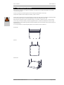
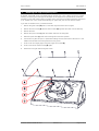
K&F�SCENA�15
User's�Manual
Important�Information,
Please�Read�Before�Use!
KLING & FREITAG GmbH
Junkersstraße 14
D-30179 Hannover
TEL +49 (0) 511 96 99 70
FAX +49 (0) 511 67 37 94
www.kling-freitag.de
Revison 1.0
Released: 03.05.2010
User's manual
K&F SCENA 15
Table of contents
1
Introduction
4
1.1
Symbols in User's Manual
4
1.2
Information about this User's Manual
4
2
Product�Description
5
2.1
Scope of Delivery
5
2.2
System Requirements for Use
5
2.3
Overview of Components
6
2.4
Required Tools
6
2.5
Accessories
6
3
Safety�Instructions
7
3.1
Mounting the Speakers / Wall and Ceiling Installation
7
3.2
Notes for Mounting the Speakers
7
3.3
Preventing hearing damage
7
3.4
Protecting the Speakers / Operating Safety
7
4
Suspending�the�Speakers
9
5
Rotating�the�high�frequency�horn
10
6
Configuration�and�Connecting�Diagram
11
6.1
1 Channel Mode
11
6.2
2 Channel Mode
12
6.3
Operations with an Additional Subwoofer
13
7
Wiring�instructions
13
8
Operating�the�Speakers
13
9
Transport�and�Storage
15
10
Maintenance�and�Care
15
11
Technical�Specifications
16
12
Measuring�diagrams
16
13
Dimensions
17
14
Disposal
18
14.1
Regulations for Disposal
18
14.1.1
Germany
18
14.1.2
EU, Norway, Iceland, and Liechtenstein
18
14.1.3
All other Countries
18
KLING & FREITAG GMBH © 2010
Revision 1.0
Page 3 of 18
User's manual
1.
K&F SCENA 15
Introduction
Thank you for your decision to buy a KLING & FREITAG sound system. To guarantee a trouble-free operating of the equipment and to allow your KLING & FREITAG SCENA 15 system to achieve its full potential please read the operating instructions carefully before use. With the purchase of a SCENA 15
system, you have acquired a large sound system with the highest possible quality and performance capabilities. As the owner of a SCENA 15 system, you now have a versatile and highly professional tool
which, when operated properly, is a true pleasure to use.
1.1
Symbols�in�User's�Manual
This symbol indicates the possibility of life-threatening danger and a health risk for persons. Not following these instructions may result in serious health problems including potentially fatal injuries.
Warning
This symbol indicates a possibly dangerous situation. Not following these instructions may cause minor
injuries or cause property damage.
Caution
This symbol gives instructions for the proper use of the described products. Not following these instructions may cause malfunctions or property damage.
Important
This symbol indicates notes that help you to handle the described products easier.
Tip
1.2
Information�about�this�User's�Manual
© Kling & Freitag GmbH, 2010, all rights reserved.
All specifications in this manual are based on information available at the time of publishing for the
features and safety guidelines of the described products.
Technical specifications, measurements, weights and properties are not guaranteed.
The manufacturer reserves the right to make product alterations within legal provisions as well as
changes to improve product quality.
All�persons�who�use�the�speaker�system�must�have�this�guide�and�all�further�information�for
safe�operations�available�to�them�during�assembly,�disassembly,�and�use.�The�speaker�system
may�neither�be�set�up�nor�used�until�this�manual�has�been�read,�understood�and�kept�readily
available�on�site.
We appreciate any input with suggestions and improvements for this manual. Please send this to us at
the following address:
[email protected] or to:
KLING & FREITAG GMBH Junkersstr.14 D-30179 Hannover.
Phone +49 (0) 511 96 99 70, Fax +49 (0) 511 67 37 94.
KLING & FREITAG GMBH © 2010
Revision 1.0
Page 4 of 18
User's manual
2.
K&F SCENA 15
Product�Description
The SCENA 15 is a high performance stage monitor with a hidden pole mount flange and 4 flying
points. These features make it possible to use it not only as a highly professional stage tool but also
as a PA speaker. The SCENA 15 is equipped with a rotatable high frequency horn with a coverage angle of 50° x 70°. It has a hidden connector panel with an adjacent cable outlet for inconspicuous cable routing. The SCENA 15 can be used in the operating modes '1 Channel Controlled' and '2 Channel Controlled' (1 channel active / 2 channel active), thus providing flexible application possibilities. Its
elegant design suitable for TV and galas provides for a positive appearance on all stages and sets the
SCENA 15 apart from other stage monitors in its performance class.
2.1
Scope�of�Delivery
•
Floor monitor incl. hidden pole mount flange for mounting on a stand.
•
User's Manual
2.2
System�Requirements�for�Use
K&F�CD�44�Digital�System�Controller
LAB.GRUPPEN�FP�10000Q:
Connector�Panel�CP�4
These�components�will�be�referred�to�as�'K&F�SystemRack'�in�this�manual.
KLING & FREITAG GMBH © 2010
Revision 1.0
Page 5 of 18
User's manual
2.3
K&F SCENA 15
Overview�of�Components
1
2
3
4
5
6
7
8
1.
Front�grille with a hexagonal hole pattern and acoustic foam behind it.
2.
High�frequency�horn, rotatable
3.
Pole�mount�flange, covered. For using the monitor on a speaker stand.
4.
Handle�rail
5.
Plastic�sliders, 4 x on the bottom, 3 x on the side
6.
M8�thread�inserts, 4 x, for K&F eyebolt M8, for suspension of the speakers
7.
Operating�mode�switch, for selecting the operating modes 1 channel or 2 channel.
8.
Speakon�connector, 2 x 4-pin NLT4MP (parallel)
2.4
Required�Tools
To�rotate�the�high�frequency�horn:
•
3 mm Allen key for loosening the front grille
•
4 mm Allen key for loosening the horn tweeter
2.5
•
Accessories
K&F eyebolts M8 x 20
KLING & FREITAG GMBH © 2010
Revision 1.0
Page 6 of 18
User's manual
3.
3.1
K&F SCENA 15
Safety�Instructions
Mounting�the�Speakers�/�Wall�and�Ceiling�Installation
The speakers may only be mounted to wall and ceilings by qualified personnel.
The technicians responsible for assembling the speakers on site are responsible for the safe setup and
use of the speakers and guarantee this.
Warning
Never use signal cables or power cords for suspending, aligning or securing the systems.
Before carrying through ceiling and wall installations, it is essential to consider the load capacity of
walls, ceilings and panelling as well as the stability and type of the construction. If there is wall panelling, for example, it is then necessary to examine the solidity of the wall and use the appropriate wall
plugs.
Make sure to comply with the stipulated tightening torques.
If not otherwise stated in this manual, only original KLING & FREITAG parts may be used for mounting
the speakers. The use of other parts - in particular parts by other manufacturers - is not permitted in
this case.
Ensure that all installation connections comply with the applicable safety guidelines and that the size
and strength are sufficient.
Ensure that all connections are secured against coming loose and that only authorized, statically tested
and correctly sized supports, mounting equipment, wire ropes and chains are used.
As a basic principle, you must visually inspect all components of the speaker before every use. If there
are signs of wear, cracks, or deformation, then you must replace the parts immediately. The visual inspection also includes checking the screwed connections on supporting elements.
The information described here does not relieve the user of the duty to follow the given safety requirements and legal regulations.
3.2
Notes�for�Mounting�the�Speakers
Mount the speakers securely. To avoid injury or damage, always be sure to mount the speakers securely so that they do not fall.
Caution
Please note that speakers can move as a result of vibrations. To prevent them from falling from their
mounted position, they must be secured properly.
When laying out the connecting cables, make sure that nobody can trip.
3.3
Preventing�hearing�damage
Avoid beeing too close to operating speakers. This equipment is capable of delivering sound pressure
levels in excess of 90 dB/SPL, which may cause permanent hearing damage.
Caution
KLING & FREITAG GMBH © 2010
Revision 1.0
Page 7 of 18
User's manual
3.4
K&F SCENA 15
Protecting�the�Speakers�/�Operating�Safety
SCENA 15 speakers may only be used in combination with a K&F SystemRack. See chapter [System Requirements for Use] on page 5.
Caution
In general, audio signals should not be overdriven. This may be caused by mixing consoles, equalizers,
effect equipment, etc. and should be indicated on this equipment. When a power amplifier is overloaded at the output (clipping), then the amplifier activates a clipping warning signal. In any case, the
signal must be reduced as soon as it sounds unnaturally distorted.
For�damage�caused�by
•
overloading the speakers
•
using the speakers without K&F SystemRack
we do not assume warranty and excludes liability for possible consequential damage.
The�following�signals�may�damage�the�speakers:
•
permanent high-level signals with high frequency and continuous noise from feedback.
•
permanently distorted high-level signals.
•
noises, which occur when the amplifier is on while equipment is being con-nected, disconnected
or switched on.
Do�not�install�devices�in�any�of�the�following�places:
•
where the devices are permanently exposed to direct sunlight.
•
where the devices are exposed to high moisture or rain.
•
where the devices are exposed to strong vibrations and dust.
Damage�caused�by�the�speakers'�magnetic�fields
Speakers are permanently surrounded by a magnetic field, even when they are not connected. Therefore, during transport and placement of the speakers, it is important to ensure that there is always approx. 1 m between the speakers and magnetic data media and computer/video monitors.
KLING & FREITAG GMBH © 2010
Revision 1.0
Page 8 of 18
User's manual
4.
K&F SCENA 15
Suspending�the�Speakers
With the help of the M8 x 20 eyebolts available as accessories from KLING & FREITAG, the SCENA
15 can be suspended
Screw in at least two of these eyebolts into the existing M8 threads on the sides.
Suspend the speaker with the help of shackles, ropes or chains.
Ensure that all connections are secured against coming loose and that only authorized, statically tested
and correctly sized supports, mounting equipment, wire ropes and chains are used.
Warning
Note that the suspension points on the hall ceiling (i.e. shackles, suspension points, or chain points)
must comply with the accident prevention regulation BGV C1 (Event and Production Sites for Stage
Presentations) or comparable applicable national standards, and the total load must be approved by an
authorised expert.
It is not permissible to suspend anything else from the bottom of the SCENA 15.
Horizontal
Vertical
Under floor
KLING & FREITAG GMBH © 2010
Revision 1.0
Page 9 of 18
User's manual
5.
K&F SCENA 15
Rotating�the�high�frequency�horn
By default, the SCENA 15 has a coverage angle of 50°x70° (hor. x vert.). When you use it as a stage
monitor, you have a good coverage into the depth of the stage and an optimal lateral sound field
boundary on the stage. When used on a speaker stand, the practice-orientated directional characteristic of 70°x50° (hor. x vert.) results automatically. For special uses, the horn can also be rotated.
If you wish to rotate the horn, proceed as follows:
1.
Remove the grille screws (A) with a 3 mm Allen key and remove the front grille.
2.
Remove the horn screws (B) and the chassis screws (D) opposite them with a 4 mm Allen key.
3.
Remove the horn.
4.
Remove the spacer tubes (C) that are located under the mounting tabs.
5.
Place the spacer tubes (C) under the mounting tabs of the new position.
6.
Turn the horn by 90° and put it in place while making sure that the socket of the horn is in the
middle of the woofer and securely latches into the groove.
7.
Screw on the horn tightly again using the longer horn screws (B).
8.
Screw in the shorter chassis screws (D) again.
9.
Mount the front grille with the 8 grille screws.
KLING & FREITAG GMBH © 2010
Revision 1.0
Page 10 of 18
User's manual
6.
6.1
K&F SCENA 15
Configuration�and�Connecting�Diagram
1�Channel�Mode
To avoid unnecessarily assigning controller channels, this operating mode is recommended for most
usages.
In 1 channel mode, the high frequency driver and the low/mid-range chassis are controlled by one
controller channel. The internal crossover takes over the frequency separation for tweeter and low/
mid-range.
In 1 channel mode, a maximum sound pressure of 134 dB SPL is reached.
In general, this sound pressure level is fully sufficient for use as a stage monitor.
KLING & FREITAG GMBH © 2010
Revision 1.0
Page 11 of 18
User's manual
6.2
K&F SCENA 15
2�Channel�Mode
You can use the 2 channel operating mode when you have to slightly increase the maximum sound
pressure level.
In 2 channel mode, a maximum sound pressure of 136 dB SPL is reached.
KLING & FREITAG GMBH © 2010
Revision 1.0
Page 12 of 18
User's manual
6.3
K&F SCENA 15
Operations�with�an�Additional�Subwoofer
If you want to operate the SCENA 15 with an additional K&F subwoofer, you must activate the filter
button B (100Hz mode) on the CD 44 for the SCENA 15. In doing so, you will get an optimal coupling
to the K&F subwoofer systems.
1�Channel�Mode
2�Channel�Mode
Activate 'Filter B' for the
LSBlock [SCENA 15 1CH].
Activate 'Filter B' for the LSBlocks
[SCENA 15 2CH LF] and [SCENA 15 2CH HF.].
If necessary, adjust the correct level balance with the output gain of the subwoofer on the CD 44.
7.
Wiring�instructions
•
Before connecting your SCENA 15 loudspeaker switch off all equipment and turn down all level
controls.
•
Only use high-quality speaker cables with a sufficient wire gauge. The wire gauge depends on
the length of the speaker cable.
Minimum�Wire�Gauge�(mm²)
=�Required�Cable�Length�(m)�/�(2�x�Speaker�Impedance�(Ω))
•
For connections to the power amplifier inputs, please use 2-pin shielded microphone cable (balanced) with high-quality connectors.
•
Avoid ground loops.
•
Please pay attention to the pin assignments shown in this manual.
•
Make sure that the +/- polarity of the speakers at the amplifier is correct. When simultaneously
using power amplifiers from different manufacturers, be sure to use the correct specific pin configuration. It may be necessary to modify the pin configuration on the power amplifiers or on
the connectors leading to them.
•
Upon completing the wiring, ensure that the connected speaker channels are working in phase.
To do so, use i.e. a phase checker. A phase error can also be recognized when the connected
channels are used simultaneously. During simultaneous use the bass frequencies become notably
quieter or the mid-frequencies such as voices cannot be located.
•
If several loudspeakers are connected, the signal can be linked through parallel from one loudspeaker to the next. Please make sure that the total impedance of the loudspeakers R(Ω) is not
lower than the minimal impedance indicated on the power amplifier.
1/R1�+�1/R2�+�1/R3�+�...�=�1/Rtotal
Important
KLING & FREITAG GMBH © 2010
Revision 1.0
Page 13 of 18
User's manual
8.
Important
K&F SCENA 15
Operating�the�Speakers
•
Switch off all equipment and turn down all level controls of the mixing console and the power
amplifiers.
•
Wire your SCENA 15 systems according to the instructions in this manual.
•
Switch on the mixing console first, then the controller and the power amplifier. Always use the
before mentioned switching order. Otherwise switching noises may damage the sound system.
•
If there is interference, turn off all appliances in the reverse order and check all cable connections.
•
Successively turn up the individual power amplifier channels and send a signal with low volume
to the system. Check to see if the desired signals are applied to the intended speakers and make
sure there is no interference.
With�controller: The SIGNAL LEDs of the CD 44 Controller will light up if the output level is
higher than -45 dB. Your system should now be ready for operation.
•
Turning down the input level controls may not always prevent distortions in the input section
of the power amplifier, especially if this section has a relatively low headroom. A clipping signal
may not be displayed by the clipping indicator then! To prevent signal interruptions or damages
to the speakers, turn the level controls of the power amplifier to the maximum position, if possible. Set the output level of the mixing console or the controller to a level that doesn't overload
the power amplifiers or decrease the limiter threshold of the controller.
•
When turning off the system, the input controls for the power amplifiers should be turned
down first followed by the power switches of the amplifiers. After that, the other appliances can
be turned off.
KLING & FREITAG GMBH © 2010
Revision 1.0
Page 14 of 18
User's manual
9.
K&F SCENA 15
Transport�and�Storage
The SCENA 15 is protected against short-term moisture. It should still be stored, transported, and used
under dry conditions, though. The SCENA 15 System is not designed for long-term use in a corrosive
environment.
Make sure that the system is adequately ventilated during longer storage periods so that possible
residual moisture can escape from the equipment.
Furthermore, you should ensure that the SCENA 15 System is protected from mechanical strain to prevent possible damage.
We recommend using suitable transport and storage cases and the optional soft cover that protects
from the above-mentioned influences.
10. Maintenance�and�Care
1.
For the owner and user, it is mandatory to be aware of the safety relevance of speakers that can
be flown.
It is, therefore, highly essential to carry through meticulous and well-documented maintenance
procedures and inspections.
Warning
The SCENA 15 system can exhibit signs of wear over the years, i.e. from mechanical strain, transport damage, corrosion, or improper handling. If speakers are to be flown, this always means
there is a high safety hazard.
As a basic principle, you must visually inspect the SCENA 15 System every time you suspend it and
take it down. For fixed installations, you must inspect the speaker for signs of wear at regular intervals.
During these inspections, you must especially look out for deformations, cracks, dents, damage to
threads, and corrosion. Mounting devices such as shackles, chains and wire ropes also have to be
checked for signs of wear or deformation carefully.
If as a result of these checks any uncertainty should arise with regard to safety or if specific faults
are found, the SCENA 15 system may no longer be used and you must send in the product to
KLING & FREITAG GmbH for inspection and repairs, if necessary. If defects are ascertained, then
you must send in the product to KLING & FREITAG GmbH for inspection and repairs, if necessary.
The�inspection�requirements�vary�depending�on�application�and�country�of�use.�Observe
the�requirements�that�are�relevant�for�you.�If�in�doubt,�contact�local�authorities.
In many countries, regular inspection of mounting components and accessories is required. In
most cases (e.g. german BGV C1), an additional annual inspection is required that must be done
by a technical expert. Additionally, a detailed inspection carried through by a legally certified or official authority is required every four years.
In this context, it is very important to keep an inspection log book. In this inspection log book, the
data for every used accessory is entered at the periodic inspections, making the data available at
all times for possible inspections. This book should document maintenance measures and inspection intervals and contain parts lists.
2.
Twice a year, turn on the switch in the speaker’s connector area so that it stays functional.
3.
The Polyurea synthetic coating used by KLING & FREITAG is impact proof and highly resistant. We
recommend using protective coverings or cases to help avoid damaging the paint during i.e. continuous mobile use
4.
To replace the filter foam, send the front grille incl. foam to KLING & FREITAG GmbH. Upon payment for expenses, the grille with the new covering will be returned.
KLING & FREITAG GMBH © 2010
Revision 1.0
Page 15 of 18
User's manual
K&F SCENA 15
11. Technical�Specifications
Design
2-way passive system, bass reflex tuning (equalisation via CD 44), switchable between 1- or 2-channel mode
Frequency�range�-10�dB
49 Hz - 20 kHz
Frequency�range�+/-�3�dB
65 Hz - 18 kHz
Coverage�angles�nominal
50° x 70° (hor. x vert., horizontal use)
Power�Handling
400 watts nominial
1)
2)
800 watts program
Max.�SPL�(1m)
134 dB SPL (1 channel mode)
136 dB SPL (2 channel mode)
Components
15" coaxial chassis with 1.4" horn tweeter
Impedance�(nominal)
8Ω
Connectors
2 x Speakon 4-pol NLT-4MP (parallel)
Enclosure
Frame-reinforced 15mm Multiplex enclosure with
35° monitor angle and highly resistable Polyurea
synthetic coating in black, integrated pole mount
flange, ergonomic handles on the sides for horizontal and vertical transport, hidden connecting panel, 4 flying points M8 on the sides, 7 non-abrasive
plastic sliding feet, ball proof steel grille with black
acoustic foam behind the grille.
Dimensions
640 x 355 x 568 mm
Weight
23,5 kg
Accessories
K&F eyebolts M8 x 20
1) Pink noise 40 - 5000 Hz, 2 h; 2) as 1) but with 50% duty cycle
The K&F SystemRack is required for operation of the K&F SCENA 15.
12. Measuring�diagrams
Frequency response CD 44 Filter B 'OFF'
Frequency response CD 44 Filter B 'ON'
10
0
-10
-20
-30
KLING & FREITAG GMBH © 2010
Revision 1.0
Page 16 of 18
User's manual
K&F SCENA 15
13. Dimensions
KLING & FREITAG GMBH © 2010
Revision 1.0
Page 17 of 18
User's manual
K&F SCENA 15
14. Disposal
14.1
14.1.1
Regulations�for�Disposal
Germany
It�is�not�allowed�to�dispose�of�used�electrical�equipment�as�domestic�waste.
But�please�do�not�dispose�of�them�at�official�collecting�points�for�recycling�either!
All KLING & FREITAG products are plain business-to-business (B2B) products. KLING & FREITAG products labelled with a waste bin sign have thus to be disposed of by KLING & FREITAG alone. Please call
KLING & FREITAG at the number stated below if you have a KLING & FREITAG product to be disposed
of. We will offer you a straightforward and professional disposal with no costs involved.
If there is no waste bin sign on one of your KLING & FREITAG products, because it has been sold before 24 March 2006, then by law the owner is in charge of the disposal. In this case we will be happy
to assist and offer you proper ways of disposal.
Telephone�number�to�call�about�the�disposal�of�used�KLING�&�FREITAG�products:�+49�(0)
511-96�99�7-0
Explanation: With the ElektroG (law relating to electrical and electronic equipment and appliances) we
have complied with the EU-directive on waste electrical and electronic equipment (WEEE, 2002/96/EC).
From 03/24/2006 onwards KLING & FREITAG GmbH has thus labelled all products mentioned in
the WEEE with a sign with a crossed out waste bin and a white bar below. This sign indicates that
the disposal as domestic waste is prohibited and that the product has been put into circulation on
03/24/2006 at the earliest.
KLING & FREITAG GmbH has been legally registered as a manufacturer with the German registration
office EAR. Our WEEE registration number is: DE64110372.
For the German Registration office EAR we have accredited that our products are soleB2B products.
14.1.2
EU,�Norway,�Iceland,�and�Liechtenstein
It�is�not�allowed�to�dispose�of�used�electrical�equipment�as�domestic�waste.
From 08/13/2005 onwards KLING & FREITAG GmbH has thus labelled all products for EU-Member
countries as well as Norway, Iceland and Liechtenstein (except Germany) mentioned in the WEEE with
a sign with a crossed out waste bin and a white bar below. This sign indicates that the disposal on domestic waste is prohibited and that the product has been put into circulation on 08/13/2005 at the
earliest.
Unfortunately the European directive WEEE has been complied with implementing different national
provisions of law throughout all member countries, which makes it impossible for us to offer consistent solutions for the disposal throughout Europe.
Responsible for complying with these provisions of law is the local distributor (importer) of each country.
For proper disposal of used products in accordance with these local provisions in the mentioned countries of the European Union (except Germany) please ask your local dealer or the local authorities.
14.1.3
All�other�Countries
For proper disposal of used products in accordance with local provisions in other than the above mentioned countries please ask your local dealer or the local authorities.
KLING & FREITAG GMBH © 2010
Revision 1.0
Page 18 of 18