1
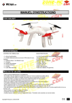
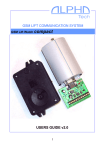
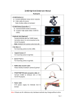
Appendix 1: WLToys V303 Supplemental Information I am brand new to flying this type of craft, and have only been flying smaller quads and simulators for about 4 months now. The following information is what I’ve learned from the fantastic and ever-helpful hobbyists on the RCGroups thread “The WLToys V303 (350 sized) "Seeker" quadcopter review”. I know there will be more hobbyists joining the ranks, and some with less experience than me, so I’m hoping this will help in their pursuit of successfully flying the V303 Seeker. I am a hobbyist and have no association with WLToys, thus this is not an official/sanctioned WLToys document. Various brands and websites are referenced in this document, of which I have no association as either a representative or as a shareholder. I am merely a customer and offer these brands & vendors as examples only. WARNING 1. Do not update Flight Controller with firmware from Zero Tech. WLToys has a modified version and if updated you will not be able to fly without updating to the WLToys version of the Flight Controller Firmware which is now available. (remediation) 2. Do not attach V303 battery when quad is upside down. The quad must be upright so that FC initialization/calibration does not cause stability issues. (remediation) Table of Contents Additional Resource Materials ................................................................................................................................................ 2 Functional Check Out and Configuration ................................................................................................................................ 3 Firmware ................................................................................................................................................................................. 5 LED Status ............................................................................................................................................................................... 5 Semi-documented TX Features/Functions.............................................................................................................................. 5 Transmitter ......................................................................................................................................................................... 5 Belly Connectors ................................................................................................................................................................. 6 Belly Wires (New Version) .................................................................................................................................................. 6 Loading PC Software for FC (PC-GCSoftware) ..................................................................................................................... 6 Problem Resolution................................................................................................................................................................. 7 Battery Charger (Numerous symptoms/errors).............................................................................................................. 7 Dead Battery or Battery unable to take a full charge ..................................................................................................... 7 I can’t find a 2700 mAh battery to replace my stock battery or to have multiple batteries .......................................... 7 Transmitter (TX) won’t power up, even though the batteries are brand new ............................................................... 8 Quad won’t power up .. no lights and no sounds .. when the battery is first attached. ................................................ 8 When inserting LiPo and powering up Beeps are heard but there is no LED indicator showing Red/Green................. 8 Initialization went great can’t get GPS lock .................................................................................................................... 8 It initialized and I got GPS lock but I can’t arm the motors. ........................................................................................... 9 1 Jan-11-2014 Appendix 1: WLToys V303 Supplemental Information Got it into the air and it went berserk ............................................................................................................................ 9 After FC initializes I get constant yellow lights. .............................................................................................................. 9 I see yellow lights on Quad when flying in IOC mode when flying aggressively ............................................................. 9 I crashed it, what should I do .......................................................................................................................................... 9 After ARMing I can’t take off. The Quad tips over ........................................................................................................ 10 I mistakenly upgraded firmware for FC ........................................................................................................................ 10 No 12V power from Belly Connector ............................................................................................................................ 10 No power to quad ......................................................................................................................................................... 10 Videos Look Terrible...................................................................................................................................................... 10 Can’t ARM motors & rapid red/green LED.................................................................................................................... 10 Vibrations when flying / not all motors running when Armed ..................................................................................... 10 Can’t load FC update ..................................................................................................................................................... 10 Calibrating ESCs..................................................................................................................................................................... 10 Replacing V303 Transmitter/Receiver .................................................................................................................................. 11 ZeroGCS / Android Wi-Fi Information ................................................................................................................................... 11 Module Installation ........................................................................................................................................................... 12 Software Installation ......................................................................................................................................................... 12 Enabling the Wi-Fi Module Connection ............................................................................................................................ 13 Target Lock .................................................................................................................................................................... 13 Fly to Point .................................................................................................................................................................... 13 Waypoints ..................................................................................................................................................................... 14 Follow Me (Old Android App) ....................................................................................................................................... 14 Additional Resource Materials This appendix was created in June 2014 (updated throughout August), so versions and locations may have changed after this document was published / updated. The flight controller in the V303 Seeker is the Zero Tech YS-S4 and documentation can be found here. The PC software for connection to the V303 is the driver and the PC application [PC-GCS software-S4V2(support servo gimbal)] or Android Phone software located here. Blue LCD charger not covered in “Getting Started” is here contributed by RCKatBat and James. A cleaned up softcopy of the Getting Started Manual can be found here contributed by HotWheelsMojo. Internal dimensions of the battery compartment are 27.6mm (H) x 34.8mm (W) x 110mm (L). The lid for the battery compartment is 14mm deep. It will accommodate a Turnigy 2200mAh 25C LiPo at a significant cost savings, as well as the supplied 2700mAh LiPo. Make sure whatever battery you select has a XT60 power plug to match that of the quad. 2 Jan-11-2014 Appendix 1: WLToys V303 Supplemental Information Images of the V303 Seeker including externals, unboxing and internals are here Prop Guards: They are now offered by WLToys via your local point of sale. Users also report the DJI Phantom Guards work just fine Props: Nothing has been found yet to perfectly replace the stock or replacement props provided by WLToys. Props are 9*4.7 units and the inner diameter of the rotor hub measures around 8mm (keyed). Marking on prop indicates 9047. Other items to consider purchasing: Prop balancer ($6US-$20US), LiPo Balanced Battery Charger (~$35US) Balance Plug LiPo Battery monitor ($5US), WLToys spare props (~$8US for a set of 4) and Servo Tester (~$5US). Trying out FPV/OSD? o Antenna connector confusion resolved. The difference between SMA and SMP RP. o Very helpful guide to connectors used on V303 and FPV gear. o On Screen Display (OSD) thread specific to low cost ZeroUAV flight controller (used in V303). Functional Check Out and Configuration 1. DO NOT follow the sequence of steps in the “Getting Started Guide” and do not attach props to quad .. yet. 2. Charge LiPo battery per instructions in “Getting Started” #4 a. There are at least two chargers being shipped and only the original, expected to be pre-production is referenced in the Seeker “Getting Started Guide”. b. Second charger is blue with LCD. It was originally shipped with a 2A power supply which is insufficient to charge the included 2700 mAh LiPo. You’ll know you have this problem if when you are charging you receive ER 2 error. This error usually surfaces when the battery is charged to ~12.1v. i. You need to report to your distributor that you have this defect and ask for an upgraded power supply to remedy the problem. ii. You can use an existing battery charger rated at least at 3A or use a separate LiPo balanced charger c. A third charger (black) is also being shipped. It seems every manufacturing wave is shipping with a different charger. We believe this is the manual for it. 3. Place 4 AA cells into the transmitter following “Getting Started” #1 a. There have been problem with the batteries not making contact when you turn the TX on. To fix, use a thin knife blade or piece of metal to reform (or bend) the flat plates a little which normally contact the + side of the AA battery, or b. Report problem to your distributor and wait for a new transmitter, while watching your seeker gather dust. 4. Put the charged battery into the battery compartment. Do not connect to power .. yet 5. Turn on TX 6. Connect battery to Seeker power leads 7. You should now see a brief light show as the Flight Controller get initialized (Red/Yellow flashing) 8. When you get to Red/Green flashing (trying to get 6 GPS satellites) or Green flashing (Got >6 satellites) you are good. 9. You are now ready to arm the rotors (without props) to test that all are operational 10. ARM Rotors: Read “Getting Started” #6 but … before you push sticks to ARM position, you must first move Throttle Stick straight down to bottom, then move left stick to lower left, and right stick to lower right at the same time. a. All rotors should be spinning.. but it is hard to tell without props on 3 Jan-11-2014 Appendix 1: WLToys V303 Supplemental Information i. ii. iii. iv. v. 11. 12. 13. 14. 15. 16. 17. With both sticks at center position no rotor should be stopped Push right stick to top (Mode 2) for a moment and you should see at least 2 rotors stop Push same stick to bottom (Mode 2) for a moment and you should see some more stop Do the same thing with the right stick to the left and right. You should feel at this point that all rotors are work, through a process of elimination.. if one rotor always looked like it was NOT spinning you have a problem and should report such to the distributor or go to step 14 and then return to this step. b. Now disarm motors.. Remember throttle down first and then move both together to extreme bottom and furthest left and right. Calibration of Accelerometers and Gyros (Critical). Doing this has fixed some real weird stability problems. Do this anywhere, but on a level surface. a. Video Calibration of Compass (Critical) using “Getting Started” #12. This must be done away from metal and power and should be done outside away from any building and radio/cell towers. a. Video b. On newer Firmware when dancing with the Quad in the vertical position the LED might be red rather than green. Nothing is wrong, proceed insuring the LED doesn’t go out. Calibration of Transmitter using “Getting Started” #11 can easily be done inside your home / building. a. Video b. There is an alternate way via a USB connection to your computer if you have problem doing it with #11 OPTIONAL STEP: Since there have been numerous reports related to problems with the internals a precautionary measure prior to flight is to open the V303. While this will likely void the warrantee … I’m not sure it has a warrantee to void. Remove 4 legs (2 screws each) with wrench, all other screws are removed with Phillips screwdriver, remove 2 screws 1 on right and 1 on the left edge of quad body, then remove only the screws on the arms that are Phillips screws (5 per arm). Here’s what to look for based on what others have discovered: a. Check all visible cables in area of Flight Controller (FC) to make sure they are plugged in. b. If you find a connector on the power distribution board (power to the FC) covered in silicon and appearing to be bent scrape off the silicon and inspect for a loose connection. Some users have found problems under the silicon. c. Check soldering on the power distribution board (the FC sits on this). Look for shorts, globs of solder where they shouldn’t be and dull solder (usually an indication of a cold solder joint) d. On the arms: Check for shorts on the 3 wires from the motors to the ESC (circuit board). Make sure the 2 power lines to the ESC off of the power distribution board are connected and not shorted. There should be a capacitor (black can) between these power leads on the ESC. Some have sheared off, so you might want to add a zip-tie around the power leads and some silicon/glue between the capacitor and the ziptie. Now you can put your props on following “Getting Started” #0. Make sure to match the arrow designator on the props to the arrow on the arm. a. The props are keyed and appear to have some extraneous plastic inside the hub. Do not remove it. It does however make it difficult to balance props with some balancers. b. Read all the rest of “Getting Started” especially #10, since you now have some pretty sharp blades on the Seeker TIME to FLY Time for photos/videos a. Balance the Props (search youtube), it is also possible to balance the hubs (search youtube). 4 Jan-11-2014 Appendix 1: WLToys V303 Supplemental Information b. Ensure Quad arms are all the same height (most important if you have ever crashed). c. Ensure Prop blades are not bent (important if you have ever crashed). With props on Quad measure the distance from the table to a prop tip, spin prop 180% and measure the other one. Move the quad to next motor and repeat. Replace the blade if any not at the height as the majority. Bending may cause a stress fracture on the blade and is not a recommended fix, since this fracture can lead to a crash of the quad when flying. d. If using the isolated GoPro holder slip 4 zip ties through the center of the isolators once installed. Do not snug them up. This will prevent your GoPro from falling to the ground, and minimize any damage or isolator loss if crashing to the ground. e. You probably have to re-adjust your camera to remove the props or legs from getting in your videos. Don’t expect to get you best video on your first flight. Firmware There are at least 4 versions of the firmware created by WLToys; 141043, 141045, 141047, and 141075. So far no one has experienced any problems with the latest update to the firmware. Update 141047 eliminated a FC problem where the V303 engines will stop when the throttle is turned to minimum position, so you should consider upgrading to it or a more recent version. LED Status The printing of the LED status on the Seeker was pretty messed up in the “Getting Started Guide” #5 Semi-documented TX Features/Functions Let’s start with the mystery slider. In the middle of the front of the TX there is a black vertical piece of plastic that moves up and down. It has no mechanical/electrical function and is just sliding piece of plastic. Transmitter There is a 4 button pad to the right of the LCD. 5 Jan-11-2014 Appendix 1: WLToys V303 Supplemental Information 1. Left Button – sequences through TX Modes 1-4 as displayed on the LCD control the function of sticks on the TX. 2. Right Button – Channel 7 values of 0-2 a. Snapshot Mode??? - Momentary press/release toggles from value 0-1-0 and shows a camera icon on lower left of LCD b. Video On ????- Holding button for a few seconds toggles to value 2 with blinking camera c. Video Off ????- With Blinking camera in display and holding button again the value changes to 4 and blinking camera disappears, and is accompanied by two chirps of the TX. 3. Top Button – Camera Pitch Up: Channel 8 value 0-1 Up arrow displays on LCD when pressed 4. Bottom Button – Camera Pitch Down: Channel 8 value 0 & 2 Down arrow displays on LCD when pressed Belly Connectors On the belly of the V303 are a set of connectors. While looking at the plugs on the belly of the Quad where the Micro USB is on top the wiring is as follows: USB Port Power – Black (Ground) Power – Red (+12v) Com – Black (TX?) Com – Red (Ground) Com – White (RCV?) The power connector is connected to the power distribution board in the Quad which attaches directly to the battery. The connector used is somewhat unique: Molex Part Number #50-57-9402 SL™ Crimp Housing, Single Row, Version G, Positive Latch, 2 Circuits $.26US at DigiKey Some users have found they cannot get power off of the Belly power connector and have found a PC board problem below the power distribution board on the connector belly PC board. Here is a more detailed picture of what needs to be corrected by bridging. I haven’t found any documentation on the Com Port other than Black and White is either TX or RCV. The COM port attaches to the FC and support the Wi-Fi Telemetry module. The Wi-Fi modules for this FC come with plugs that will directly work with this connector. Belly Wires (New Version) Users have found a three wire belly wire with a connector on some of the newer models which can be connected with a Gimbal unit enabling pitch control of the Gimbal from the transmitter. Here are some photos of the internal wiring and the belly wire extending from the square hole in the bottom of the quad. We have verified that at least one user with this connector is running firmware version 141043. These connectors will allow the Transmitter to successfully control the pitch of a Gimbal. Loading PC Software for FC (PC-GCSoftware) Download the Drivers and PC software. Links can be found in the Additional Resource section of this document. The software once downloaded needs to be decompressed since they are in ZIP and RAR format. If you don’t already have support to un-compress these files, consider installing this software. 6 Jan-11-2014 Appendix 1: WLToys V303 Supplemental Information Warning: If you connect the quad to the USB and plug it into the PC running the software before you start the V303, you will be prompted with FC firmware upgrade. Exit app immediately. Do not update firmware (unless you are planning to upgrade with WLToys FC upgrade). Unplug USB, Re-insert and start software again. 1. 2. 3. 4. 5. 6. 7. 8. Load latest USB-Serial driver. Plug micro USB into the under-belly of V303 Power Up V303 Plug USB cable into computer (after Red- Green / Green – Green). Driver might show a yellow exclamation mark (use Control Panel/System/Device) .. be patient After about 5 minutes the exclamation mark disappeared. Start the PC software Press Connect to USB. This button may be only partially visible on your display. You may see a bit of the top of the button under the Read, Save and Default buttons. If so click there. 9. It connected on computer (Win7) perfectly. Problem Resolution The following represents common problem discovered in the first three manufacturing waves. If you’ve discovered any of these problems within 4 days of receiving the quad, you need to contact the store/distributor to report the problem. In most all cases they’ll want a video which depicts the problem. They may offer to give you a partial refund/credit or accept return of the quad. The choice is yours, but keep in mind shipping charges back to the store/distributor may be prohibitive. The following solutions can be performed by you in lieu of returning the quad. Return is always an option to all of the following problems: 1. Problem Battery Charger (Numerous symptoms/errors) 2. Dead Battery or Battery unable to take a full charge 3. I can’t find a 2700 mAh battery to replace my stock battery or to have multiple batteries 7 Possible Resolution 1. Buy a balanced LiPo charger. There are several available starting at ~$35US all over the internet 2. Buy or use a power supply rated at ~3Amps. Also consider buying a lipo battery tester. They are <$5US and are indispensable. They tell you the full charge of the battery and the charge of each individual cell. Some charger problems are actually a dead cell in the battery. Contact distributor with video showing the problem and ask for replacement battery or credit/refund to cover you getting a battery Your distributor/store should have a replacement 2700 mAh battery for ~$35US from WLToys. An alternative is a 2200mAh battery which will give you a few minutes less flying time but cost only 1/3 the price. Turnigy 2200mAh 25C LiPo fits just fine. See resources on dimensions of battery bay of the V303. Don’t expect to add the cover and depth together since you’ll need room for the wires and plugs. The dimensions of the battery case as well as the 3s (3 cells) and 25C (25 amp constant current) parameters are critical in Jan-11-2014 Appendix 1: WLToys V303 Supplemental Information 4. 5. Transmitter (TX) won’t power up, even though the batteries are brand new Quad won’t power up .. no lights and no sounds .. when the battery is first attached. 6. When inserting LiPo and powering up Beeps are heard but there is no LED indicator showing Red/Green 7. Initialization went great can’t get GPS lock 8 determining a replacement. If you find a battery with the right dimensions which is 3S values and has a value of >25C it will work just fine. Earlier TXs had badly formed battery plates in the battery compartment. Bend out the flat plates and you’ll be fine. 1. Make sure the LiPo battery is fully charged 2. Remove the 22 screws holding the two plastic shells together and the legs. We need to get inside. a. Look for: i. The FC needs to get power (green LED on FC) and usually beeps as it is initializing. ii. Loose connectors. There are ample links to photos on the V303 internals in the Resource section. iii. Sloppy soldering which allows various components to be shorted. iv. Pieces of soldering lying on the board but not melted/connected to the board. v. Bent connectors or connectors at a weird angle. vi. Check that the black cylindrical capacitors on each ESC (on the 4 arms of the quad) are present. They can be reinforced with a bit of silicon sealant between the capacitor and the ESC board. Most all power problems experienced so far can be traced to the problems above. To rectify the problem fix it. 1. Remove the 22 screws holding the two plastic shells together and the legs. We need to get inside. a. Look for: i. Loose LED connector where it meets the Flight Controller (FC). It is marked on the FC. If not, then reference photo links in Resource Section. b. Re-seat connector Make sure you are outside and have view of the sky. The first time you try and get a lock may take up to 1 minute. It usually only take about 30 seconds on subsequent GPS locks. If you waited a couple of minutes: 1. Remove the 22 screws holding the two plastic shells together and the legs. We need to get inside. 2. The GPS is attached to the top of the shell behind a sheet of cooper foil. a. Check the cable coming out of the copper and going to a circuit board next to the Flight Controller (FC). b. Check the cable leaving the circuit board. c. Check the cable going form the circuit board to Jan-11-2014 Appendix 1: WLToys V303 Supplemental Information 8. It initialized and I got GPS lock but I can’t arm the motors. 9. Got it into the air and it went berserk the FC. 3. Reset cable or repair any broken wires in those cables. 1. Make sure that the Trim tabs on the Transmitter (TX) are in neutral position. There are two trim tabs for each joystick. If you move tabs up/down, left/right you’ll hear a beep. The trims are neutral when you hear a distinctive beep, unlike the rest. 2. Make sure the TX is in the appropriate mode. TX mode is displayed in the LCD and followed by a number. Mode 1 has thrust/elevation on the right stick, mode 2 uses the left stick. To change mode use the left button in the set of buttons to the right of the LCD. Press for a few seconds and you’ll scroll through the 4 modes. 3. Configure TX using procedure in Functional Checkout section #11 4. Insure TX switches (on the top of TX) are pushed back 5. Try to arm motors again Check motors with props off and initialize compass, accelerometers and gyros following the procedures in Functional Checkout #10a, #12 & #13. This might be an ESC problem if motors don’t spin or Flight Controller if they do spin, but not stable in flight. 10. After FC initializes I get constant yellow lights. 11. I see yellow lights on Quad when flying in IOC mode when flying aggressively 12. I crashed it, what should I do This can happen if you powered up the V303 upside down. Here is a procedure which has worked for at least one user: What finally fixed it was a combo of leaving micro USB from the V303 attached to PC with the Auto Pilot configuration GUI open and plugging / unplugging battery then Clicking connect USB button again. While in its inoperable state even though it would say USB connected there was no stick action i.e. they wouldn't budge in the Auto Pilot configuration GUI.- despite showing centered. There appears to be a problem with the Flight Controller (FC) not respecting the defined flight envelope limitations when out of “Manual Mode” (both switches pushed back). This has led to flips and the ability to lose control of the V303. Until the firmware for the FC is update by WLToys, you’ll need to be especially careful when flying aggressively. Several distributors (Banggood.com) have replacement parts for the most common damaged items. Search on V303 in the store of your choice. I was pleasantly surprised at the cost to expedite a shipment (3-5 business days) from China to the USA. It was only $8US for both halves of the shell. I found a phenomenal product for repairing cracks to the plastic shell. It’s called RapidFix. You can search online. Not only does it effectively joint the plastic but allow you to build up additional strength in the area of the break. Cracked GPS ceramic patch antenna can be replace with a 25mm 9 Jan-11-2014 Appendix 1: WLToys V303 Supplemental Information 13. After ARMing I can’t take off. The Quad tips over 14. I mistakenly upgraded firmware for FC 15. No 12V power from Belly Connector 16. No power to quad 17. Videos Look Terrible 18. Can’t ARM motors & rapid red/green LED 19. Vibrations when flying / not all motors running when Armed 20. Can’t load FC update x 25mm patch antenna (Frequency 1575.42MHz). While the original one is 2mm thick, thicker units (ublox NEO 6M Gps antenna) have reports of faster GPS lock with more Satellites than the original. Here is a link to more info. You have might have the props on the wrong arms. Insure all props and arms have matching circular arrow in the same direction. You can fix this by upgrading to the WLToys build of the firmware. You can find it here. Reference the chapter on Belly connectors to insure correct polarity. Note: Users have found a broken PC board which has prevented 12V to the connector as referenced in the Belly connector section of this document. Users have reported a power lead problem where power lead to battery has come apart at the battery connector. Balance the Props and ensure they are not bent. This is the largest contributor to jello in your videos. Also consider balancing the hubs. (Both procedures have numerous youtube videos). Recalibrate the compass. Make sure the LED stays lite the whole time you are rotating the quad. If it goes out do it again … slowly and precisely. Don’t forget to save calibration. Calibrate ESCs There are two things you can try. 1) try another computer … don’t ask why but in many cases that has solved the problem. 2) You may have an open wire or short between the belly usb and the FC. Open up the quad, unplug usb cable at the Flight Controller and cable directly to the Flight Controller. Calibrating ESCs Symptoms requiring calibration of ESCs are as follows: When arming rotors, not all blades are spinning at the same rate with throttle in neutral position Excessive vibration of quad when in the air and having GPS Lock After a crash when replacing a V303 ESC Calibration requires the direct connection of the receiver throttle channel to each ESC to be calibrated. Since the V303 stock receiver uses S.bus and multiplexes all receiver channels on a single control line this is NOT possible on the V303 without using other components. I’ll cover 3 ways that users have used done calibration and the additional components required. In ALL cases the symptoms listed above were rectified, and overall flight characteristics were improved. 1. Replace Flight Controller with APM controller. There is no need to replace stock TX or Receiver. Connect APM controller to RCVR, power and ESCs (all of them). The APM FC should bind just fine. Here is a video showing the procedure. After calibration you can replug everything into the stock FC. 10 Jan-11-2014 Appendix 1: WLToys V303 Supplemental Information 2. Replace TX and Receiver, and wire each ESC control wire directly to Throttle channel on RCVR (disconnect each from V303 FC), and calibrate one at a time. You’ll need to bind the TX and RCVR first. Here is a video of how to calibrate. More details can be found here. 3. You can also use an Arduino to calibrate. The web article is here. Two critical numbers are needed to make the sketch work on a V303. They are “MAX_SIGNAL" and "MIN_SIGNAL”. Use 1800 (V303 Max µS) and 1200 (V303 Idle µS) respectively. You can calibrate all at the same time without any changes to your RCV, TX or FC. 4. Use cheap Servo Tester. Here is an excellent video calibrating V303 ESCs using this method. This is this most affordable means of calibration. Replacing V303 Transmitter/Receiver It is possible to use your own or a more sophisticated transmitter and receiver with the V303 while still using the WLToys firmware and not losing any functionality. Your transmitter/receiver should be capable of at least 6 channels, but you’ll need 8 channels to control a gimbal if desired. While the WLToys receiver uses what appears to be SBus to connect a single control line to the FC, users have not been able to use any receiver in SBus mode. So your 4 main quad channels will plug into the FC using the PWM protocol (which most all receivers support). For Mode 2 plug as follows (image): AIL = CH1 ELE = CH2 THR = CH3 RUD = CH4 CH5 = CH5 CH6 = CH6 You need to reverse throttle via your transmitter in most cases. You might need to remove the plastic housing of your receiver to get it to fit in the body of the V303. Also check the WLToys GUI to insure switches are working and RTH can be enabled. Gimbal attachments with pitch control should be made directly from your receiver and not via the belly wire. You might be able to unplug this servo line from the FC and attach to channel on receiver. There is no need to change the firmware to support non-V303 transmitters. ZeroGCS / Android Wi-Fi Information There are a couple of sources of a Wi-Fi communication module for the WLToys V303 Seeker which uses the plugs located on the belly of the quad for power and communications to the FC: DIY Zero YS S4 X4 X6 S4V2 Flight Controller WiFi Module Y.S. Zero Flight Controller WIFI Module w/Antenna Support S4 X4 X6 X4-P ~$ 39.90 US ~$109.34 US There are a lot of interesting capabilities once installed. You’ll need to download the PDF manual called; Gemini Autopilot User Manual V2.0 from the Zerouav.com site. This manual covers a lot more than the Ground Control software. You can skip everything till Chapter 10. The capabilities of the module include: 11 Jan-11-2014 Appendix 1: WLToys V303 Supplemental Information All Calibrations – Compass, Transmitter, Centering Sticks, Gyros Flight Parameter Edit: Roll/Pitch sensitivity, Sway compensation, Throttle Sensitivity, Altitude and Distance Limits, Vertical and Horizontal Max speed limits. Flight Data: GPS data, Lat, Lon, # of satellites, velx, vely, Distance to home, Altitude, Flight Time, Battery Voltage, Motor Balance, Vibrate and Shake states, Attitude and Flight angles … Mapping capabilities using Google Earth allows; Setting Waypoints, and Center Focal point mode Records a log of flight characteristics and maintains the last 1 minute in a file. Allows you to fly via your phone/tablet Creation of Log file. This thread may be helpful in deciphering the log file. Pretty exciting .. so let’s get started. Module Installation The following installation directions apply to the less expensive Module. It comes with the Communications (Com) cable with a plug at both ends and a power cable with a plug at one end and bare wires at the other end. Belly connection description is here. I had to modify the Com plug by filing down a ridge on the existing plug. It also comes with the antenna. Software Installation There are three versions of the Android GCS and they have different capabilities. Here are the three versions: 1. We’ll call this the “old version”: GCS for Android 2013 (4/15/2013) 2. And the “new version”. This is posted on the ZeroUAV site: Phone-GCS software-S4V2(support servo gimbal) (3/18/2014) They are different. The latest version does NOT contain all the function of the old version. We are currently testing the differences … be patient, or if you can, test and report back to me for inclusion. Function Parameters can be changed and saved to the FC and retained between power cycles. Data Map/Paramters Page 1 Fly to Point Target Lock Waypoints Follow Me Old Version Reported as NO. Some users have been successful when upgrading to latest firmware from WLToys. Similar New Version Yes Reported as Yes Reported as Yes Reported as Yes Yes Report as Yes Report as Yes Report as Yes No Similar Once downloaded and uncompressed you’ll need to move the AFK file to the SD card on the phone/tablet. In order to install it locally I needed to download another Application “AppInstaller by FunTrigger” from the Play Store. Start AppInstaller, find SD card and install the AFK file. The GCS App will have the name Zero-GCS. 12 Jan-11-2014 Appendix 1: WLToys V303 Supplemental Information The following connection directions apply to the less expensive Wi-Fi Module. Enabling the Wi-Fi Module Connection 1. 2. 3. 4. 5. 6. Open the lid of the Wi-Fi module using a small screwdriver. Plug in cables between belly of Quad and Wi-Fi module. Turn on transmitter Install Battery into Quad Let Quad go through initiation sequence till Red Green sequence At android device start “Settings” application a. Click on Wireless & Networks b. Connect Wireless to “LR-WIFI” (Wi-Fi module) c. In module you see a micro-switch inside the module by the cable connectors. Press that once d. Put lid back on Wi-Fi Module e. Exit “Settings” Application 7. Start Zero-GCS application 8. Select Android App Menu a. Select “Set” b. Update the “Hand Mode” to reflect TX modes and Press “OK” c. This app menu will also allow you to quit the Zero-GSC application using “Quit” Before you start changing anything reference: Gemini Autopilot User Manual V2.0 from the Zerouav.com site. I have yet to take this off the bench, so I can’t give you any additional info at this time .. stay tuned! Target Lock Allows the quad to travel around a point of interest keeping the nose of the quad pointing towards the point of interest no matter where the quad is flown. 1. 2. 3. 4. 5. 6. From Android device select the Map and click at the object to become the target. You should see a smiley face. Select the SWP tab (at top of screen) Select PTZLock and “OK” the Yellow smiley face should change to a Purple star Change the radius to the target using the Elevator stick (Mode 2: Right stick moving up-down) Change rotation around target with Aileron stick (Mode 2: Right stick moving left-right) Cancel Target Lock by Selecting SWB/Quit PTZLock/OK Fly to Point The quad will move to the target and hover. If the distance is < 10m then it will travel with the nose unchanged. If distance to target is >10m then the quad will turn its head to point to target during its travel to the target. Be careful that the target is within sight and that there are no obstructions between quad and target. 1. From Android device select the Map and click at the object to become the target. You should see a smiley face. 2. Select the SWP tab (at top of screen) 3. Select FlyToPP and (the text will turn grey), then “OK” the Yellow smiley face should change to a Purple star on the Map 4. Cancel Target Lock by Selecting SWB/Quit PTZLock/OK 13 Jan-11-2014 Appendix 1: WLToys V303 Supplemental Information Waypoints WARNING: Do not use “Auto Make Waypoints” mode. There are reports that it corrupts internal data, and forces a reboot of the FC. All mixing and limits need to be rechecked prior to attempting a flight. You can set a sequence of targets and the manner (altitude & speed) in which the quad travels to each and what happens (hovering time) at each waypoint. Be careful that the altitude of your flight clears any obstructions between each waypoint. So how do you get to maps when you’re in the field and don’t have Wi-Fi service or Telco service? First using just the App without connecting to Wi-Fi module but connected to home Wi-Fi. Find the areas where you might want to setup Waypoints. You have to work around the “Communication Disconnected" message … use "locate"/"Search" then when you have it Locate/Save Location … for each map you want to cache. Now when you get to your flying area and attach Android to Wi-Fi Module, you'll just need to load the correct map (which was cached when saved). Refer to section 12.2.7 in the GeminiAutopilotUserManual referenced earlier in this section for details. Follow Me (Old Android App) You can only use this if your Android device has GPS capabilities. If it does the quad will follow you and your phone/tablet anywhere you go keeping its nose pointing towards the location of the android device. 1. I can’t find the “settings” in the actual program to enable this capability. Stay-tuned 14 Jan-11-2014