1
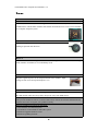
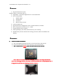
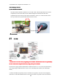
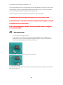
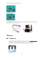
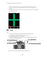
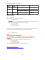
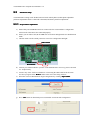
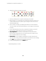
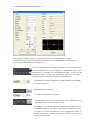
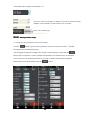
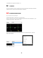
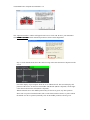
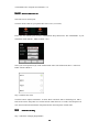
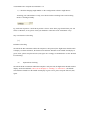
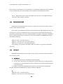
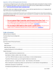
YS-S4 Multi-rotor Autopilot User Manual V1.4 YS-S4 Multi-rotor Autopilot User Manual V1.4 Zero UAV (Beijing) Intelligence Technology Co. Ltd 1 YS-S4 Multi-rotor Autopilot User Manual V1.4 1. In-Box.............................................................................................................................................. 3 2. Functions......................................................................................................................................... 4 3. Installation....................................................................................................................................... 5 4. Connections..................................................................................................................................... 6 4.1 Assembly.............................................................................................................................. 6 4.2 Real connection demo.......................................................................................................... 7 5. SOFTWARE.................................................................................................................................... 8 5.1 Install Phone GCS................................................................................................................ 8 5.2 Tx setup................................................................................................................................ 9 5.3 Parameter Setup..................................................................................................................10 5.3.1 PC parameter adjustment....................................................................................... 11 5.3.2 Phone parameter setup........................................................................................... 14 5.4 Tx calibration..................................................................................................................... 15 5.4.1 PC calibration transmitter channel......................................................................... 15 5.4.2 Phone Calibration Tx............................................................................................. 17 5.5 Failsafe Checking............................................................................................................... 17 6. Adjustment outdoors......................................................................................................................19 6.1 GPS/Compass Calibration................................................................................................. 19 6.1.1 Compass alignment by PC..................................................................................... 19 6.1.2 Compass alignment by Phone................................................................................ 20 6.2 Motor Arm.......................................................................................................................... 22 6.3 Motor Mixer Checking....................................................................................................... 23 7. Task................................................................................................................................................ 24 7.1 Servo Gimbal..................................................................................................................... 24 8. Firmware Upgrade......................................................................................................................... 25 Appendix........................................................................................................................................... 27 LED Indicator meannings........................................................................................................ 27 Flight Mode Description.......................................................................................................... 29 8.1.1 Phone/ Tablet Control.............................................................................................29 2 YS-S4 Multi-rotor Autopilot User Manual V1.4 1.In-Box ■Harware □Software ■ Main controller X1 The MC (Main Controller) with its integral Inertial Measurement Unit (IMU),combines and communicates with the other modules and external electronic devices to carry out its function as a complete autopilot system. ■GPS+COMPASS X1 The GPS/Compass module is for sensing the orientation of the aircraft by reading its position and direction ■LED X1 The LED indicates current flight status of the craft. The light shows information such as flight mode, number of satellites in view and battery used. ■ Power ModuleX1 Supplies regulated power for the autopilot and the Wi-fi module. Input voltage is from 3S to 6S Lipo and output is 5.7v ■GPS BracketX1 The GPS+COMPASS is sensitive to magnetic interference. This bracket is used to mount the GPS module where necessary and to keep it far away from EMI sources. ■Warranty Information Card X1 This provides Product Serial No., Purchase Date. Please fill out the relevant information and return to Zero UAV to register your product warranty. Software available on website for download: □ GCS Software for Android System □ GS Software for PC Windows XP/7/SP3 system □ Firmware Upgrade Software on PC. □ Firmware updating assistant. 3 YS-S4 Multi-rotor Autopilot User Manual V1.4 2.Functions 1) Supported multirotor layouts: Quad X4, Quad +4, Hexa X6, Hexa +6. 2) Upgradable – upload new flight firmware via mini USB cable. 3) Four working modes i) Stabilize flight ii) Altitude hold iii) Auto hover iv) Return to home & land. 4) Control methods: RC 5) Support parameter configuration via PC or Android mobile (via WIFI). 6) Reciver supported: Common receiver、PPM 7) Gimabl supported: Servo gimbal 8) LED Light display’s the mode, GPS lock & low power warning. 9) Standard safety features include motor arming protection, failsafe auto RTH & auto landing. 3.Installation 1) YS-S4 V2 Module Installation a) The YS-S4 Module should be placed level on the main body of the aircraft. b) For best results install at the Center of Gravity (CoG) of the aircraft. ” MUST point towards the head of the aircraft: Arrow” c) The “ Front Arrow Note: There is no need to add extra dumping, the S4 V2 can adapt most kind of craft. For some bigger frame, it is hard to control (sometimes the craft jump upward). It is suggested to purchase the dumping structure as below: 4 YS-S4 Multi-rotor Autopilot User Manual V1.4 S4V2 dumping structure 2) GPS Module Installation The GPS module should be installed on a level GPS stand, which is higher than the electrical components on the aircraft. This ensures minimal magnetic field effect from the other component on-board, such as power cables, transmitters, camera, etc. Ensure that the sticker faces up and the arrow point towards the head of the aircraft. Arrow towards 4.Connections 4.1 aircraft head Assembly Note: A. Make sure to use the factory originally power module, manufacturer has no responsibility for the result if the autopilot is burnt by using other power module. B. The Power supply module and the WI-FI module must have a 3 to 6 cell (3S-6S) LIPO battery. The voltage range would therefore be 10.8V-25.5V. Normally this would be your main flight battery. C. Motors and ESCs (Especially when several ESCs are together), can cause serious magnetic interference so the GPS module must be as far away from these as possible A non-ferric bracket 5 YS-S4 Multi-rotor Autopilot User Manual V1.4 must be used with the arrow on the GPS facing forward. Also the battery connection carries a high current and may result in a strong magnetic field. Keep the battery wires as far away as possible from the GPS module otherwise your aircraft may fly in circles! D. Make sure power the servo of gimbal seperately when using servo gimbal. E. WHITE cable is signal cable, RED cable is positive pole, BLACK cable is ground. 。 COM po rt F. Only USB connector can be used for Parameter setting and firmware upgrade upgrade。 port is ectended connector (to connect WIFI). G. S4 V2 does not support ESC calibration, user need to calibrate the ESC by self. (please refer to the ESC manual) 4.2 Real connection demo 1) connect the power supply module : As shown below, one 3-core cable to connect S4 V2, WHITE-core is up, RED -core is middle, black-core is in bottom. RED cable and BLACK cable need to be soldered to the positvie pole and negative pole of battery (3S-6S Lipo). 2) LED module is connected to LED port of main controller. 3) Connect GPS module GPS module has red and balck ends, red end is connected to GPS-R port, and black end to GPS-B port. The neck faces up. 6 YS-S4 Multi-rotor Autopilot User Manual V1.4 4) Connect to receiver 5) WI-FI Module connection The WI-FI data cable is a 3-core cable, connect the end which has the lock to the WI-FI module and connect the other end to master controller. 5.SOFTWARE 5.1 Install Phone GCS Download the YS-GCS Android software from our official website http//www.zerouav.com The App must be installed to the Mobile-phone memory card. It can be installed automatically by selecting INSTALL on the APK file once in the file manager. S4V2-GCS 7 YS-S4 Multi-rotor Autopilot User Manual V1.4 Open the GCS(user need to purchase the optional WIFI module). When the data has connected, you will see the serial number and firmware version for the autopilot on the interface. After connecting your WI-FI to the GCS successfully, you can also see the real-time updated data on the "Data" Page. 5.2 Tx setup Step 1: 1) 2) 3) 4) Select fixed wing model on your transmitter. Remove any channel mixing. FUTABA Radio: All channels should be Normal (no reverse). JR, JT & WFLY Radios: Reverse all channels. Ensure your radio has two sets of two-way switches. Programme CH5 & CH6 to these switches to control the flight modes: Position1 Neutral CH6—Position1 CH6 Position1 Manual Mode CH5—Position1 CH5 Position2 Auto Mode CH5—Position2 CH5 Position 2 Return&Land Mode CH6—Position CH6 Position2 Adjust your two-way switch end points to control the flight modes: 8 YS-S4 Multi-rotor Autopilot User Manual V1.4 CH5 Position CH6 Position GPS Lock WorkingMode Position 1 Position 1 X Manual Stabilization Position 2 Position 1 GPS No Lock Manual Altitude Hold GPS Lock(above 5 satellites) X Position 2 GPS Lock(above 5 satellites) Auto Hover Return& Land Note: Return&Land mode is always first. In any mode, autopilit will return&land if CH6 is switched to position2. Step 2 Fail/Safe setup There are 2 ways of F/S: default and optional mode (1) Default F/S mode FAILSAFE: Check with your Radio manual on how to set the Receiver failsafe. Ensure that when you OFF your radio, your failsafe settings are as follows: CH5 set to position 2 CH6 set to position 2 THR set 50% (mid point) Default F/S mode only has one Return&Land mode, namely S4 V2 will command craft return and land automatically if the communication between Tx and autopilot disconnected. (2) Optional F/S setup Note: A Make sure the Tx is FUTABA transmitter. B it is not commanede to use the optional F/S setup for beginners because it is very complicated. Ensure that when you OFF your radio, your failsafe settings are as follows: CH5 set to position 2 CH6 set 50% (mid point) THR set 50% (mid point) Check with your Radio manual on how to set the Receiver failsafe. Please refer to the video to setup Tx: http://www.tudou.com/programs/view/e1ai526Mbt4/ 9 YS-S4 Multi-rotor Autopilot User Manual V1.4 5.3 Parameter Setup YS-S4 Parameter setting can be divided into two kinds: mobile phone (mobile phone adjustable parameter adjustment must be connected to the WiFi) and the PC parameter adjustment. 5.3.1 PC parameter adjustment a) Ensure that your GPS Module has been connected to the YS-S4 module. Configuration will not work if the GPS is not connected properly. b) Ensure your Tx radio is ON, & the THR stick is at bottom & flight mode is in Stabilization mode. c) Check & make sure the switch position is correct for Configuration & Flight: USB Interface Switch towards GPS interface d) Connect your YS-S4 module to your PC via the USB interface. Power up your YS-S4 with 3S - 6S lipo battery. e) Your PC may show “find a new hardware” when using the USB cable for the first time. Driver Use driver program in the ‘Driver Driver’ folder in the root of the config software. Open COM COM’: f) Select the correct COM number & begin configuration by clicking ‘Open Get g) Press ‘Get Get’ button to download your YS-S4 module current aircraft configuration. 10 YS-S4 Multi-rotor Autopilot User Manual V1.4 h) Change the Aircraft Type according to your model: i) The factory default parameters are good for normal flying in most models. j) During test flights, it is recommended to keep the altitude limit & distance limit short. E.g. 30 meters (altitude) & 50 meters (distance), upon reaching these limits the aircraft will automatically RTH & land. k) Set the ‘Cell Num’ according to your flight lipo cell numbers & ‘Volt Alert Treshold’ to 3.65. Select a smaller value when using an old battery, or select a bigger value when using new battery. l) You may adjust the Roll Sensitivity & Sway Compensation according to your aircraft behavior during test flights. Range value is between 0 to maximum 255. m) Sway Compensation Compensation: Hover & observe aircraft attitude. If it sways too much, then increase the Sway Compensation, till it is more stable. If the value is too high, you will observe oscillations. Reduce the value accordingly. n) Roll Sensitivity Sensitivity: Fly it in a straight line, if the flight is not so stable, then increase the value. If the value is too big, the aircraft will oscillate on roll. Reduce the value accordingly. Send o) Press ‘Send Send’ button to upload the newest parameters to the YS-S4. Default p) To restore the default parameters, press ‘Default Default’ button. YS-S4 default parameters is as below: 11 YS-S4 Multi-rotor Autopilot User Manual V1.4 Roll sensitivity and pitch sensitivity would affect the degree of command response in flight (Default value is 45, range 0-255), Motion Compensation can increase stability but would decrease the sensitivity (Default value is 20, range0-255). M7 is the PTZ (Gimbal) roll output and M8 is the PTZ pitch output. Roll/Pitch sensitivity is used to adjust the compensation angle of the PTZ data for your Gimbal. Your can compensate high or low for aircraft movement within a range from -127 to 127 (Note: You can enter a negative value to reverse the direction of compensation). Control different frequency gimbal servo, 50HZ,250HZ, 333HZ,400HZ setup Max flight speed. Setup maximum flight speed. To setup the Max climb/decent speed. Fill the voltage per cell required to activate a low voltage alert, for a Lipo battery this would be normally 3.65v。 The autopilot can calculate the low voltage alert according to the Cell Number filled in by the user. If your phone vibrates once every 12 2 seconds it is a reminder that the power is getting low. When it vibrates continuously it means the power is getting very low and you should land at once. YS-S4 Multi-rotor Autopilot User Manual V1.4 User can setup the height or distance by self to limit the flying distance. The maximum is 1500 meters, min 10 meter. Enter your aircraft type. 5.3.2 Phone parameter setup 1)Getting the current parameter set-up of the aircraft Click the button to get the current parameters. (Click several times if it fails) Normally the autopilot uses the default parameters. After changing any parameter settings away from the current settings you must click the button (click several times if it fails), and this will upload the revised parameters to the autopilot. If you want to recover the default parameters, you need to switch to manual mode and pull the throttle stick to the bottom and then click the button. 13 YS-S4 Multi-rotor Autopilot User Manual V1.4 5.4 Tx calibration The remote calibration of YS-S4 is divided into two kinds: mobile phone (mobile phone calibration calibration must be connected to the WiFi) and the PC calibration. 5.4.1 PC calibration transmitter channel Step 1: Select the correct stick layout Click the menu button of “ manual servo” on your PC GCS In the PC GCS which opens select the "Hand Mode" drop-down menu. The “Hand Mode” is your transmitter mode (Mode 1, Mode 2, Mode 3 etc.) Select your own operation style in the manual mode menu. The illustration shows “American Hand” which is Mode 2. Step2: Calibrate the sticks 14 YS-S4 Multi-rotor Autopilot User Manual V1.4 The ‘Adjust Transmitter’ window will appear on PC GCS. Click ‘OK’ & move your transmitter stick within 5 Seconds to their maximum positions as shown in the diagramme: Step 3: Check that the GCS shows the sticks moving in the same direction as depicted on the screen. Check the display of special place when the Tx is calibrated well. This screen displays the position of the sticks. On the left is the Rudder and Throttle (Mode 2 depicted). On the right is the aileron and elevator stick (Mode 2 depicted). When both sticks are in the middle position they are shown as green, any other position shows red except for when the throttle stick is at the bottom when it shows as yellow. When the throttle is in hover position (normally close to the middle position) it shows green. 15 YS-S4 Multi-rotor Autopilot User Manual V1.4 5.4.2 Phone Calibration Tx Select the correct stick layout Click the menu button on your phone then select "Set” (see below) In the "Set" box which opens select the "Hand Mode" drop-down menu. The “Hand Mode” is your transmitter mode (Mode 1, Mode 2, Mode 3 etc.) Select your own operation style in the manual mode menu. The illustration shows “American Hand” which is Mode 2. Step 2 Calibrate the sticks Click the button “Adjust Transmitter” on GCS “Data” and click "OK" in the dialog box. Move both sticks to their end points in a circular motion within the next 5 seconds. The autopilot will store the maximum and minimum end points and also the mid points of both sticks. 5.5 Failsafe Checking Step 1 Check the changing Flight Modes 16 YS-S4 Multi-rotor Autopilot User Manual V1.4 1) Check the changing Flight Modes via the Configuration software ‘Flight Status’: Assuming your GPS module is ready; now check whether switching between all working modes is working normally. Eg. with CH5 at position 1 and CH6 at position 1 the PC GCS "data" page should show your TX status as "Manual", if not, please check your hardware connection or RC Transmitter setup. Step 2: Fail Safe F/S checking (1) Default F/S checking Switch off the RC Transmitter whilst the autopilot is still powered, the flight status should switch to display "Go home and land", the throttle stick indicator should be in the middle and display in green. If not, please setup the fail-safe (F/S) again. It is strongly recommended to use the “Default F/S Checking” (2) Optional F/S Checking Switch off the RC Transmitter whilst the autopilot is still powered, the flight status should switch to display "Go home and land" (On Pc GCS it displays as “Landing” or “Auto-hover”) the throttle stick indicator should be in the middle and display in green. If not, please setup the fail-safe (F/S) again. 17 YS-S4 Multi-rotor Autopilot User Manual V1.4 6. Adjustment outdoors 6.1 GPS/Compass Calibration When using the S4 V2 autopilot for the first time, the GPS/COMPASS must be calibrated before arming the motors. Note:(1) Note: Compass calibration does not need to be done every time you fly but should be done when components are moved or if the aircraft flies in unexpected ways, like in circles, for example. (2) a) ALWAYS carry out this calibration outdoors, far away from metallic objects (cars, radio towers, power lines etc.). There are two way to calibrate the compass: by Phone(with WIFI module) or by PC. 6.1.1 Compass alignment by PC There are 3 steps to follow: 1.Level calibration 2.Vertical calibration 3. Save GPS/COMPASS data. Step 1 – Move CH5 & CH6 to Position 1. Step 2 – Move switch CH5 three times quickly between Position 1 & Position 2. The LED will flash BLUE for 2 second loops. You have entered Horizontal Calibration. Carefully rotate your aircraft horizontally three times. ENSURE that the BLUE LED light remains ON during this procedure. If it turns OFF, that means the aircraft is not horizontal. Adjust the position until the BLUE LED is back ON & continue with the rotation. 18 YS-S4 Multi-rotor Autopilot User Manual V1.4 Step 1 – Move CH5 & CH6 to Position 1. Step 2 – Move switch CH5 three times quickly between Position 1 & Position 2. You have entered Vertical Calibration. Carefully rotate the aircraft 3 times as shown below, always keeping the head down. Ensure the GREEN LED remains ON during the turn. If the LED turns OFF, adjust position until the GREEN LED is back ON & continue with the rotation. After completing above, place the aircraft on the ground & Move CH5 & CH6 to Position 1, then move CH5 switch quickly 3 times. The YS-S4 V2 will enter the magnetic recording & the LED will now flash GREEN. Calibration is completed when the GREEN flash turns OFF. 6.1.2 Compass alignment by Phone There are 3 steps to follow: 1.Level calibration 2.Vertical calibration 3. Save GPS/COMPASS data. Click “Compass” button on Phone GCS "Data" Page: 19 YS-S4 Multi-rotor Autopilot User Manual V1.4 Select "Horizontal Alignment" in the dialog box, and click "OK" button to start level calibration. If you don't want to keep on calibrating select "Cancel" and confirm. Carefully rotate your aircraft horizontally three times. ENSURE that the BLUE LED light remains ON during this procedure. If it turns OFF, that means the aircraft is not horizontal. Adjust the position until the BLUE LED is back ON & continue with the rotation. Carefully rotate the aircraft 3 times as shown below, always keeping the head down. Ensure the GREEN LED remains ON during the turn. If the LED turns OFF, adjust position until the GREEN LED is back ON & continue with the rotation Click "Save Alignment" the dialog box, and click "OK". Now the GCS software will automatically switch to the “Control” interface screen and it will display two circles, a BLUE one and a RED one. The YS-S4 v2 will enter the magnetic 20 YS-S4 Multi-rotor Autopilot User Manual V1.4 recording & the LED will now flash GREEN. Calibration will be completed seconds later when the GREEN flash turns OFF. The circles are shown in the picture. If the circles are more or less round, this means the calibration has been successful. If not, then you need to do the calibration again. Compass calibration does not need to be done every time you fly but should be done when components are removed or reconstructed. There is no need to recalibrate if only upgrade the firmware. 6.2 Motor Arm For safety reasons, the S4 V2 locks the motors on landing. They can only be re-armed to allow them to rotate and work after carrying out the “arming” procedure. Note: Motor arming will fail if GPS module is no connected. How to Arm the motors and unlock. To arm you push the left-hand stick to the far left and extreme bottom, the right stick to the far right and to the bottom. This is for Japanese and American convention (mode 1 and mode 2) and is called the toe-out operation (Namely /\ type). For Chinese and European operation (Mode 3 and Mode 4), you need to apply the toe-in operation to arm the motors (Namely \/ type) Enable Combined-Stick-Command (CSC) for ESC arming as shown below: 21 YS-S4 Multi-rotor Autopilot User Manual V1.4 After the CSC operation, push the THR stick slightly up. The motors should begin to turn. You need to apply more throttle to take off normally. 6.3 Motor Mixer Checking Before take-off, you still need to check your motor mix control. First let’s take the quadcopter + type as an example to simply describe how to check motor mix control (Please refer to the illustration for other aircraft configurations). You need to arm the motors and check what happens when you advance the throttle stick, if the four motors rotate at the same speed this means the motor balance is good. 1. To check the aileron channel, slightly push the aileron stick to the left, motor M4 should rotate immediately (see 1 on the illustration below), the other three motors should keep still. Push the aileron stick to the right slightly, motor M2 should rotate immediately (see 2 on the illustration below), the other three motors should keep still. 2. Check the elevator channel. According to the aircraft symmetry it should be similar to checking the aileron channel. Push the elevator stick up slightly, motor M3 should start to rotate (see 3 on the illustration below) now slightly pull the elevator stick down and motor M1 should start to rotate immediately (see 4 on the illustration below). Quadcopter X type 22 YS-S4 Multi-rotor Autopilot User Manual V1.4 Hexcopter+ type: Hexcopter X type: 7.Task 7.1 Servo Gimbal Please power the servo if use S4 V2 and gimbal. 舵机电池 GND VCC 信号 云台舵机 Connect Y1 to gimbal roll servo and Y2 to gimbal pitch servo. “Roll Sensitivity” and “Pitch Sensitivity” in the Y1/Y2 Parameter Sectionof the GCS is for adjusting the 接口 correction angle and direction of your gimbal. Gimbal Sensitivity ranges from -127 to 127. A negative number reverses the direction of travel and the size of the number affects the amount of correction. 23 YS-S4 Multi-rotor Autopilot User Manual V1.4 Use channel 7 on your transmitter for gimbal control and assign it to a knob switch. Channel 7 will now adjust your gimbal pitch location and will continue to stabilize the camera at all angles of pitch. The spare channels may be used for other applications. Normally roll servos will maintain gimbal stabilization in the middle position. If your gimbal tilts to one side it can be adjusted it by clicking “Enter Setup” in the Setting section (CH5 must in manual and the throttle set to minimum) Now the CH7 knob can be used for controlling gimbal roll. The gimbal roll’s balance position may be fixed and saved by clicking “Quit Setup”. Now CH7 will revert to controlling gimbal pitch. 8. Firmware Upgrade Note: 1) You may download the latest firmware and assistant tool from the ZeroUAV website before upgrading the firmware.. Connect the YS-S4 to the computer with Mini USB cable. Power S4 V2 and put THR stick in the bottom Open the firmware “ S4-GCS-USB.exe”, Click “Open USB” button in the “YS-S4 firmware upgrade” window. 24 YS-S4 Multi-rotor Autopilot User Manual V1.4 Click “OK” lick “select firmware file”button Click “Open”button, select upgrade produre file“s4v2-BiaoZhun-20140115-v021.bin” The program will auto-upgrade when selected the upgrade produre. 25 YS-S4 Multi-rotor Autopilot User Manual V1.4 Power-off the autopilot when it says “upgrade successfully”. Quit the firmware upgrade software and power off the autopilot. Appendix LED Indicator meannings LED See below: Flight Status LED situation Description 2 seconds GREEN and RED Manual(GPS NO LOCK) Manual(GPS LOCK) Green light blinks once per loop Manual altitude-hold 3 seconds GREEN(2) and RE 26 YS-S4 Multi-rotor Autopilot User Manual V1.4 D(1) Auto-hover 3 seconds GREEN First stage low voltage alert 2 seconds RED Final stage urgent low voltage alert 3 seconds RED Return & Landing Continuous RED flashing Magnetic compass calibration Continuous GREEN flashing IMU Error Continuous YELLOW flashing The autopilot can calculate the low voltage alert according to the Cell Number filled in by the user. Final stage low voltage alert= (single voltage alert No. - 0.05v 0.05v) X Cell No. When it is final low voltage alert, the craft will land originally (user could adjust landing pisition during landing but make sure DO NOT push the THR stick) 27 YS-S4 Multi-rotor Autopilot User Manual V1.4 Flight Mode Description Note : Note: a. Make sure ON TX first and put THR stick in the bottom b. DO NOT push THR stick to bottom position during flying c. DO NOT switch to auto-fly mode until the craft get stable in manual stabilization mode. d. Switch to manual stabilization mode if craft meet emergency in auto-fly mode. 8.1.1 Phone/ Tablet Control (1) Phone Remote Control Mode During flight, when transmitter is switched to “Auto-hover” in “GPS mode”, the aircraft will enter auto-hover mode. Now you can activate control of your aircraft via your cellphone by pressing “Enable Control” in the “Control” screen of your GCS. NB: In phone remote control mode, transmitter control will not work. 28 YS-S4 Multi-rotor Autopilot User Manual V1.4 How to control your multi-rotor by phone or tablet? Enable Control User Interface Operations Aircraft Status Circle status Red: GPS not locked Green: GPS locked. - Position Hold No Operation Position hold Level Flight Drag finger over screen: 1 up/down 2 left/right 3 left/right top, left/right bottom etc. 4) move forward/backward 5) move left/right 6) Move left/right top, left/right bottom etc. Click below the area inside the cross 1.over circle 2.under circle 3. Left of circle 4. right of circle NB: ClimbDescendTurn (1) The distance between circle and click point is proportional to flight speed. The further the distance, the faster the flying speed. (2) Time pressing control circle is proportional to Aircraft movement time 1、Climb 2、Descend 3、Rotate to left 4、Rotate to right If GPS is not located(eg. indoors), Phone/Tablet remote control function is not available. The WIFI module must be connected when use Phone/Tablet remote control mode. (2)Phone attitude control mode Phone attitude mode can be enabled when in phone control mode. Click "Enable Attitude Control" in the phone “Control” menu. After entering phone attitude mode, the color of the cross will change from Green to Blue. After exiting phone attitude mode, control will automatically revert to phone control mode. NB: Please place your phone level before enabling phone attitude mode; otherwise the aircraft will fly following your phone tilt direction after switching to attitude mode. 29 YS-S4 Multi-rotor Autopilot User Manual V1.4 Controlling the aircraft using “phone attitude control” mode Enable Control User Interface Operations Aircraft Status Circle status Red: GPS not locked Green: GPS locked - Position Hold No Operation Position hold Level Flight Tilt the phone: 1 up/down 2 left/right 3 left/right top, left/right bottom etc. 1. moving forward/backward 2. moving left/right 3. Moving left/right top, left/right bottom etc. ClimbDescendTurn 1、Press any available area on the screen and point the phone upwards; 2、Press any available area on the screen and point the phone downwards; 3、Press any available area on the screen and turn the phone left; 4、Press any available area on the screen and turn the phone right; NB: Holding & Moving distance = Flying speed, the greater the movement, the higher the flying speed. Holding time = flying time 1、Climb 2、Descend 3、Rotate to left 4、Rotate to right 1) (1 Manual Stabilization Mode a) In Manual Stabilization Mode (TX CH5&CH6 in position1), the aircraft will fly normally and stabilized in 3 axis. 30 YS-S4 Multi-rotor Autopilot User Manual V1.4 The craft may be controlled by Tx, but meanwhile it is controlled by stabilization signal of autopilot YS-S4. The final flying state is determinde by both of manual control and autoplit control. YS-S4 flight characteristic is stable calm flights. Do not fly fast, violent flights with large stick inputs when using this controller. (2) Manual Position Hold With GPS not located(statellite lock less than 5), bring CH5 to position2 & CH6 to position 1 to enter manual altitude-hold mode. In this mode, craft will hold the altitude but not hold the position. When THR stick in 50%, the craft will hover in the current altitude but not in currrent position (craft will drift when the GPS is not locked), and meanwhile craft can be controlled manually. Left/right is controlled by AILERON Stick, Up/Down controlled by ELEVATOR stick, direction controlled by RUDDER stick, height controlled by THR stick. THR stick is 50%, craft will auto-hover; THR stick is more than 50%, craft will fly upward; THR stick is less than 50%, craft will fly downward. Craft could fly to any altitude controlled by THR stick, and fly to any position controlled by other sticks. (3) Auto hover With GPS located(statellite lock more than 5), bring CH5 to position2 & CH6 to position1 to enter auto-hover mode. 1. Auto Hover a) In this mode, the aircraft will hold the position and altitude. b) Your Tx sticks should all be in the mid position. When THR stick is around mid position, craft will hover in current position (craft does not drift because GPS has locked) and may controlled manually. Left/right is controlled by AILERON Stick, Up/Down controlled by ELEVATOR stick, direction controlled by RUDDER stick, height controlled by THR stick. 2. THR stick is 50%, craft will auto-hover; THR stick is more than 50%, craft will fly upward; 31 YS-S4 Multi-rotor Autopilot User Manual V1.4 THR stick is less than 50%, craft will fly downward. Craft could fly to any altitude controlled by THR stick, and fly to any position controlled by other sticks. (4) With GPS locked (above 5 satellites locks), craft will record the home position. a) Push CH6 to position 2 to enter RTL (ruturn and land) mode . In the Return and Land mode, the craft will RTL and land automatically. b) After activation, you can only change to Stabilization Mode if you want to take over the flight controls. If you move from RTL to Auto Hover Mode, the aircraft will continue with the Return and Land process. c) On arrival at ‘Home’, the YS-S4 V2 will begin to descend. At this time, the autopilot will allow you to take over AIL and RUD controls to adjust the landing site, but THR cannot be controlled. THR control fully autonomous for decent and land. d) Altitude: If the craft is beyond 25 meters away from home position and below 20 meters altitude, the YS-S4 V2 will ascend to 20 meters before initiating RTH when enter RTL mode. If the height is higher than 20 meters, the YS-S4 V2 will maintain altitude during RTH. If the distance from home position is more than 20 meters, the YS-S4 V2 will maintain previous altitude during RTH. e) Safety: Safety Since RTH is fully autonomous and you cannot alter the flight path during RTH, to avoid accidents, it is not advisable to activate RTH too close to you or spectators. Also note to avoid sudden lost in altitude, THR stick should be above mid-point when you change the mode from RTH to Stabilized Mode. Switch CH6 to position1 from position2 to quit RTL mode. After landing the motors will stop. Move your THR stick to bottom, 5 seconds later motor will lock. Arm the motor to restart flying. 32