1
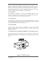
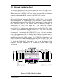
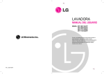
UT812-2
Rack Mount NT1
REV. 1.0.1
7/98
Important Safety Instructions
When using your telephone equipment, basic safety precautions should always be
followed to reduce the risk of fire, electric shock and injury to persons, including
the following:
1. Read and understand all instructions.
2. Follow all warnings and instructions marked on the product.
3. Unplug this product from the wall outlet before cleaning. Do not use
liquid cleaners or aerosol cleaners. Use a damp cloth for cleaning.
4. Do not use this product near water, for example, near a bath tub, wash
bowl, kitchen sink, or laundry tub, in a wet basement, or near a swimming
pool.
5. Do not place this product on an unstable cart, stand, or table. The product
may fall, causing serious damage to the product.
6. Slots and openings in the cabinet and the back or bottom are provided for
ventilation to protect it from overheating, these openings must not be
blocked or covered. The openings should never be blocked by placing the
product on the bed, sofa, rug, or other similar surface. This product should
never be placed near or over a radiator or heat register. This product
should not be placed in a built-in installation unless proper ventilation is
provided.
7. This product should be operated only from the type of power source
indicated on the marking label. If you are not sure of the type of power
supply to your home, consult your dealer or local power company.
8. (If provided with a grounded type attachment plug) - This product is
equipped with a three wire grounding type plug, a plug having a third
(grounding) pin. This plug will only fit into a grounding type power
outlet. This is a safety feature. If you are unable to insert the plug into the
outlet, contact your electrician to replace your obsolete outlet. Do not
defeat the safety purpose of the grounding type plug. (If provided with a
polarized attachment plug) - This product is equipped with a polarized line
plug (a plug having one blade wider than the other). This plug will fit into
the power outlet only one way. This is a safety feature. If you are unable
to insert the plug fully into the outlet try reversing the plug. If the plug
should still not fit, contact your electrician to replace your obsolete outlet.
Do not defeat the safety purpose of the polarized plug.
9. Do not allow anything to rest on the power cord. Do not locate this
product where the cord will be abused by persons walking on it.
10. Do not overload wall outlets and extension cords as this can result in the
risk of fire or electric shock.
Alpha Telecom, Inc. U.S.A. UT812-2 Rack Mount NT1 Manual
Revision 0798.1.0.1
i
11. Never push objects of any kind into this product through cabinet slots as
they may touch dangerous voltage points or short out parts that could
result in a risk of fire or electric shock. Never spill liquid of any kind on
the product.
12. To reduce the risk of electric shock, do not disassemble this product, but
take it to a qualified serviceman when some service or repair work is
required. Opening or removing covers may expose you to dangerous
voltages or other risks. Incorrect re-assembly can cause electric shock
when the appliance is subsequently used.
13. Unplug this product from the wall outlet and refer servicing to qualified
service personnel under the following conditions:
A. When the power supply cord or plug is damaged or frayed.
B. If liquid has been spilled into the product.
C. If the product has been exposed to rain or water.
D. If the product does not operate normally by following the operating
instructions, adjust only those controls, that are covered by the
operating instructions because improper adjustment of other controls
may result in damage and will often require extensive work by a
qualified technician to restore the product to normal operation.
E. If the product has been dropped or the cabinet has been damaged.
F. If the product exhibits a distinct change in performance.
14. Avoid using a telephone (other than a cordless type) during an electrical
storm. There may be a remote risk of electric shock from lightning.
15. Do not use the telephone to report a gas leak in the vicinity of the leak.
SAVE THESE INSTRUCTIONS
Alpha Telecom, Inc. U.S.A. UT812-2 Rack Mount NT1 Manual
Revision 0798.1.0.1
ii
TABLE OF CONTENTS
Chapter 1: Introduction....................................................................................1.1
Chapter 2: Package Contents .........................................................................2.1
Chapter 3: System Overview...........................................................................3.1
3.0 Introduction .............................................................................................3.1
3.1 UT812-2 Rack Mount NT1 ......................................................................3.2
3.1.1. Card Cage .....................................................................................3.2
3.1.2. Card Cage Rear Panel ..................................................................3.3
3.1.3. NT1 Line Cards .............................................................................3.4
3.1.4. Power Conversion Cards...............................................................3.4
3.2 External Power Supply............................................................................3.5
3.2.0 Background ....................................................................................3.5
3.2.1 Features of the external power supply............................................3.5
3.3 Network Distribution Panel......................................................................3.6
Chapter 4: System Configuration ...................................................................4.1
4.0 Introduction .............................................................................................4.1
4.1 NT1 On-Board Switch Setup...................................................................4.1
4.2 Mounting Ears Configuration ..................................................................4.3
4.3 S/T Bus Configuration.............................................................................4.4
Chapter 5: System Installation........................................................................5.1
5.0 Introduction .............................................................................................5.1
5.1 Preparation for the Installation ................................................................5.1
5.2 Installation Procedures ...........................................................................5.3
Chapter 6: System Diagnostic ........................................................................6.1
6.0 Introduction .............................................................................................6.1
6.1 NT1 Line Card ........................................................................................6.1
6.2 Power Conversion Card..........................................................................6.2
CHAPTER 7: System Wiring............................................................................7.1
7.0 Introduction .............................................................................................7.1
7.1 U-Interface Wiring ...................................................................................7.2
7.2 The U Adapter ........................................................................................7.4
7.3 S/T-Interface Wiring ................................................................................7.5
7.4 Punch Down Power Supply Wiring .........................................................7.7
7.5 PS2 (POWER SOURCE 2).....................................................................7.9
7.6 System Wiring using the UNDP-1200-2................................................7.11
7.7 S/T&PS2 Breakouts ..............................................................................7.13
Appendix A : Technical Specifications
UT812 Card Cage And UT812-2 NT1 Line card ..............................................8.1
Appendix B : Technical Specifications
PS2400 Power Supply......................................................................................9.1
Appendix C : Technical Specifications
UNDP-1200-2...................................................................................................10.1
Appendix D : Technical Specifications
ESP-B1 ............................................................................................................11.1
Appendix E : Glossary ...................................................................................12.1
Chapter 1: Introduction
The Alpha Telecom, Inc. UT812-2 is an expandable and compact rack or wall
mount Network Termination 1 (NT1) device. The UT812-2 provides up to 12
Integrated Services Digital Network (ISDN) Basic Rate Interface (BRI) line cards.
The UT812-2 allows the user to connect multiple ISDN BRI lines connected to a
centralized location.
Each of the NT1 line cards provide access to 2B+D (144 Kbps throughput). This
144 Kbps through put includes two B-Channels for circuit switched calls (Voice
and/or Data) at 64 Kbps, and one 16 Kbps for D-Channel signaling and/or low speed
X.25 packet service.
The UT812-2 is designed to conform to ANSI T1.601, 1992; T1.605, 1991;
ITU/CCITT I.430 recommendation. The UT812-2 is also compatible with National
ISDN standards with Two Binary One Quaternary (2B1Q) line code format.
Each NT1 line card provides LED indicators for power, line status, and loopback
status. Two modular redundant power cards (one for backup) insures continuous,
maintenance free service. These power cards also increase the UT812-2 reliability.
The UT812-2 installs easily in any standard 19” or 23” telephone rack. It can also
be wall mounted as required. These features allow the user to install for either large
or small office environments.
The UT812-2 provides a no compromise solution to multiple ISDN access in a
compact, flexible, easily installed unit. With over 30 staff years of experience with
ISDN technology, we are here to provide service and technical assistance that is
unparalleled in the industry. If you have questions or require additional information
not included in this manual, please feel free to contact Alpha Telecom. Thank you
for selecting the UT812-2 and Alpha Telecom, Inc.
NT1 LINE CARDS
SLOTS 1 - 12
POWER CONVERSION CARDS
SLOT 13 - 14
Figure 1.1: The Alpha Telecom UT812-2 Rack Mount NT1
Alpha Telecom, Inc. U.S.A. UT812-2 Rack Mount NT1 Manual
Revision 0798.1.0.1
1.1
Alpha Telecom, Inc. U.S.A. UT812-2 Rack Mount NT1 Manual
Revision 0798.1.0.1
1.2
Chapter 2: Package Contents
The UT812-2 is shipped in one carton, and operational upon removal. We advise
the customer to retain the shipping container and packing material in the event the
unit is ever returned (see Figure 2.1). If any of the ordered items are missing or
damaged please contact ALPHA TELECOM, INC., Customer Service
Department at (408) 895-1806.
A fully loaded UT812-2 includes:
1. One (1) UT812-2 Card Cage, twelve (12) NT1 Line Cards and two (2) Power
Conversion Cards installed.
2. One (1) Set of UT812-2 universal mounting ears (allows for 19” or 23” rack
mounting or wall mounting. See Chapter 4: Mounting Ear Configuration)
3. One (1) UT812-2 product user manual, and warranty information.
4. One (1) Molex cable to connect the UT812-2 to the power supply unit.
Figure 2.1: Shipping box and end caps should be retained in case the unit
should ever be returned for service or upgrades.
Alpha Telecom, Inc. U.S.A. UT812-2 Rack Mount NT1 Manual
Revision 0798.1.0.1
2.1
Alpha Telecom, Inc. U.S.A. UT812-2 Rack Mount NT1 Manual
Revision 0798.1.0.1
2.2
Chapter 3: System Overview
3.0
Introduction
The UT812-2 system is made up of four basic units or sub-systems (Figure 3.1)
which are as follows: the UT812-2 Rack Mount NT1, the PS2400 Power Supply, the
UNDP-1200-2 (Universal Network Distribution Panel), and the ESP-B1 Battery
Backup (refer to Appendix D for further information). The function of each of the
sub-systems and a guideline of the complete system architecture will be described in
this chapter.
Figure 3.1: The Complete UT812-2 System Architecture.
Alpha Telecom, Inc. U.S.A. UT812-2 Rack Mount NT1 Manual
Revision 0798.1.0.1
3.1
3.1
UT812-2 Rack Mount NT1
A completely loaded UT812-2 includes the following items. Each item will be
described in detail in this section.
1. One (1) card cage,
2. One (1) UT812-2 back plane,
3. Twelve (12) NT1 Line Cards, and
4. Two (2) Power Conversion Cards
5. Two (2) Universal Mounting Ears
3.1.1. Card Cage
The UT812-2 card cage is a compact aluminum enclosure, which is designed to
house the plug-in NT1 Line Cards and Power Conversion Cards that are the heart of
the UT812-2 system. It installs easily in either standard 19” or 23” telephone racks
or it can be wall mounted if desired.
The card cage provides 14 slots for accommodating twelve (12) NT1 Line Cards and
two (2) Power Conversion Cards (depicted in Figure 3.2 UT812-2 System Front
View). The NT1 ISDN BRI lines occupy the first twelve (12) positions (slots 1-12)
beginning at the left most slot of the card cage. The remaining 2 positions (slots 13
and 14), at the far right, hold the two (2) Power Conversion Cards.
The easy to read status LED’s on the front panel of each line card, allows the system
maintenance technician to diagnose and monitor the system operation.
NT1 LINE CARDS
SLOTS 1 - 12
POWER CONVERSION CARDS
SLOT 13 - 14
Figure 3.2: UT812-2 “Front View”
Alpha Telecom, Inc. U.S.A. UT812-2 Rack Mount NT1 Manual
Revision 0798.1.0.1
3.2
3.1.2. Card Cage Rear Panel
The card cage rear panel contains the connectors for the “U-Interface”, “S/TInterface”, “external power supply”, and “punch down power supply". Figure 3.3
shows the card cage rear view with all the connector positions. A description of
each cable position on the rear panel is described in this chapter. (For each
connector’s wiring, please refer to Chapter 7: System Wiring.)
3.1.2.1 U-Interface
The U-Interface is completed via a 50 pin female Amphenol connector. This
connection normally connects to the Sixty-Six (66) punch down block (RJ-21X
connector) provided by the Local eXchange Company (LXC.)
3.1.2.2 S/T-Interface
The S/T-Interface is completed via a 50 pin female Amphenol connector. The other
end of the 50-pin cable may be terminated in a variety of different ways (please refer
to “Network Distribution System” section page 3.5).
3.1.2.3 Power Supply
The external power supply connector is completed via a three (3) pins Molex
connector. Only two pins are used for the UT812-2. The Molex power cable is
supplied with the unit.
3.1.2.4 Punch-Down Power Supply (Not applicable for North American users)
The punch-down connectors can provide up to sixteen pairs of “+48V DC” for
Power Source One (PS1). Twelve (12) pairs of wires are provided by the UT812-2
system.
Figure 3.3: UT812-2 Rear Panel
Alpha Telecom, Inc. U.S.A. UT812-2 Rack Mount NT1 Manual
Revision 0798.1.0.1
3.3
3.1.3. NT1 Line Cards
Each UT812-2 card cage can hold up to twelve (12) NT1 line cards.
The NT1 line card is hot swapable. This feature allows the system maintenance
engineer to either configure or examine one of the particular BRI lines without
interrupting other ISDN BRI operation.
3.1.4 Power Conversion Cards
There are two power conversion cards per UT812-2 card cage. These power
conversion cards are located on the right of the front panel. Both power conversion
cards perform the same function.
Although the system will operate with only one card installed, the use of an
additional card (redundant backup) provides instant, uninterrupted power should
there be a failure in one of the conversion cards. This redundancy design ensures
that service is maintained and functioning properly with minimum risk of
interruption.
Alpha Telecom, Inc. U.S.A. UT812-2 Rack Mount NT1 Manual
Revision 0798.1.0.1
3.4
3.2
External Power Supply
3.2.0 Background
In North American, the ISDN CO does not supply the power to the ISDN CPE, for
the ISDN phone, however, it is required a power supply source located in the middle
of the ISDN CO and ISDN CPE. This power method is called Power Source 2
(PS2). In general, only the ISDN phone requires the PS2 provision.
In Europe and Japan, the ISDN CO provides the power to the ISDN CPE through
the U-Interface. The power scheme used in Europe and Japan is called Power
Source One (PS1). The PS1 is not supported in North America.
3.2.1 Features of the external power supply
The following features are required for the external power supply that is compatible
with the UT812-2 system.
a) “Central power” or “Bulk power” system for centralized location (either in a
closet or a building switching room) management.
b) Provide the power to the UT812-2 system and the PS2 to the ISDN CPE.
c) Supply “+48V DC” with battery backup (in the event that normal premises
powering should fail).
d) Support multiple UT812-2 systems to minimize the spacing in the switch room.
e) Cost effective for the multiple UT812-2 systems.
Due to the consideration of the features and market requirements, Alpha Telecom
recommends the PS2400 for the UT812-2 system.
The PS2400 (Figure 3.4) is a basic model power supply and can provide power for
up to two (2) UT812-2 rack mount NT1 systems (supports up to 24 ISDN BRI).
The punch down power supply will not be described in this manual. This is due to
the fact that this feature is designed for environment required PS1 that is not used in
North America.
Figure 3.4: PS2400 power supply
Alpha Telecom, Inc. U.S.A. UT812-2 Rack Mount NT1 Manual
Revision 0798.1.0.1
3.5
3.3
Network Distribution Panel
The network distribution system is used to connect the ISDN CPE to the UT812-2
system. The UT812-2 supports a 50 pin Amphenol connector for the S/T-Interface.
Before connecting to the ISDN CPE, some wiring conversion from the Amphenol
connector to the standard RJ-45 connector of the ISDN CPE is required.
This wiring conversion can be accomplished by either the traditional patch panel or
the Universal Network Distribution Panel-1200-2 (UNDP-1200-2). For the punch
down block approach, the installer needs to refer to Chapter 7, System Wiring, for
the detailed pin assignments. The UNDP-1200-2, manufactured by Alpha Telecom,
is a distribution panel (for the multiple ISDN S/T-Interfaces) designed to
accommodate the UT812-2 rack mount NT1. The UNDP-1200-2 provides
tremendous flexibility and ease of installation in both “single system” applications
(one UT812-2) or “multiple system applications (two or more UT812-2s). Figure
5.2 shows a typical installation using the UNDP-1200-2. The UNDP-1200-2 also
provides a convenient access point for line testing and monitoring at the actual point
of connection. Termination to the UNDP-1200-2 is via a 50 pin male Amphenol
cable at the opposite end of the S/T-Interface cable. The most important feature of
the UNDP-1200-2 is its ability to provide flexible, cost effective, “plug and play”
installations of multi-line ISDN systems. The UNDP-1200-2 can supply up to
twelve (12) ISDN BRI, and each BRI can multi-drop into two ISDN CPEs. This
multi-drop design allows additional ISDN CPE installed in one ISDN BRI. Figure
3.5 shows the UNDP-1200-2 front panel as well as the description of each
connector. For more information on the UNDP-1200-2, please contact Alpha
Telecom Inc.
Figure 3.5: UNDP-1200-2 Front Panel
Alpha Telecom, Inc. U.S.A. UT812-2 Rack Mount NT1 Manual
Revision 0798.1.0.1
3.6
Chapter 4: System Configuration
4.0
Introduction
To ensure the UT812-2 system operates normally, the installer needs to make sure
the NT1 line cards are configured properly. Each NT1 line card provides two onboard switches for configuring the S/T-Interface environment. These switch
settings will be described in this chapter.
The UT812-2 and the UNDP-1200-2 can be installed in either a 19” or 23”
standard telephone rack or wall mounted, depending on your requirements. This
is accomplished with the use of the universal mounting ears supplied with the
unit. A detailed description of installing the mounting ears will also be presented
in this chapter.
4.1 NT1 On-Board Switch Setup
Two on-board switches, SW1 and SW2, are provided on the NT1 line cards for
configuring the S/T-Interface line performance (line termination and bus
configuration). Figure 4.1 shows the NT1 line card switch position and switch
locations.
Figure 4.1 NT1 Line Card On-Board Switch Positions
Alpha Telecom, Inc. U.S.A. UT812-2 Rack Mount NT1 Manual
Revision 0798.1.0.1
4.1
The first switch, ”SW1”, on the NT1 line card is used for the S/T-Interface
terminating resistance setting. This switch is located in the middle of the NT1
line card (depicted in Figure 4.1). Three positions are provided for this switch.
The setting function for each position is listed in Table 4.1.
Position
One (1)
Two (2)
Three (3)
SW1- Setting Function
Open Circuit
50 terminal resistance
100 terminal resistance
Table 4.1 NT1 Line Card Switch One Setting Functions
The second switch, ”SW2”, on the NT1 line card allows the user to program the
S/T bus configuration. This switch is located in the bottom left corner near the
front panel (depicted in Figure 4.1). Two positions (ON and OFF) are provides by
this switch. The setting function for each position is listed in Table 4.2.
Position
SW2- Setting Function
ON
OFF
Point-to-point, extended passive bus
Short passive bus
Table 4.2 NT1 Line Card Switch Two Setting Functions
Alpha Telecom, Inc. U.S.A. UT812-2 Rack Mount NT1 Manual
Revision 0798.1.0.1
4.2
4.2 Mounting Ears Configuration
The UT812-2 is shipped with a pair of universal mounting ears. These universal
mounting ears allow the unit to be mounted in a variety of methods. These methods,
suitable for most applications, include the standard 19” telephone rack, standard 23”
telephone rack and typical wall mounting.
The mounting ears are secured to the card cage unit with 4-40 phillips-head machine
screws. There are two mounting locations on the sides of the card cage unit - a front
set and a rear set. By removing these screws and repositioning the ears as shown in
Figure 4.2, the UT812-2 will adapt readily to the installation environment.
Figure 4.2 Three possible mounting positions for the universal mounting ears
For 19” standard telephone rack-short side to the outside, long side to the cage
For 23” standard telephone rack-long side to the outside, short side to the cage
For Wall Mounting: Mount ear to the rear set of mounting holes with the short
side facing toward the wall and the long side to the cage (See Figure 4.3).
When used in the “wall mounting position”, the mounting ears provide the
offset from the wall required to route the cabling to and from the unit.
Figure 4.3 Wall Mount Configuration
Alpha Telecom, Inc. U.S.A. UT812-2 Rack Mount NT1 Manual
Revision 0798.1.0.1
4.3
4.3 S/T Bus Configuration
The following figures display sample S/T Bus Configurations.
Maximum distance between two TRs is
200m (600ft)
TR
TR
SW2
SW1
BUS TIMING
S/T Termination Switch
ON
OFF
3
2
1
Figure 4.4 Point-to-Multipoint (Short Passive Bus) Configuration
Alpha Telecom, Inc. U.S.A. UT812-2 Rack Mount NT1 Manual
Revision 0798.1.0.1
4.4
TE4
TE2
TR
TE3
TE1
Maximum distance between TE1 and TE4 is
31.25m (100ft)
SW1
SW2
S/T Termination Switch
BUS TIMING
ON
3
2
1
OFF
Figure 4.5 Linear (Extended Passive Bus) Configuration
Alpha Telecom, Inc. U.S.A. UT812-2 Rack Mount NT1 Manual
Revision 0798.1.0.1
4.5
TR
Maximum distance between S/T
jack and TE is 1000m (3300ft)
SW2
SW1
BUS TIMING
S/T Termination Switch
ON
OFF
3
2
1
Figure 4.6 Point-to-point (End of Passive Bus) Configuration
Alpha Telecom, Inc. U.S.A. UT812-2 Rack Mount NT1 Manual
Revision 0798.1.0.1
4.6
TE1
TE3
TR
TE4
TE2
Maximum distance between S/T
jack and TR is 500m (1600ft)
SW1
SW2
BUS TIMING
S/T Termination Switch
ON
OFF
3
2
1
Figure 4.7: Cluster Multipoint (Extended Passive Bus) Configuration
Alpha Telecom, Inc. U.S.A. UT812-2 Rack Mount NT1 Manual
Revision 0798.1.0.1
4.7
TE2
TE1
TE4
TE3
TR
TE5
TE6
TE7
TE8
Maximum distance between S/T jack and TR is 200m (600ft)
SW1
SW2
S/T Termination Switch
BUS
ON
3
2
1
OFF
Figure 4.8: Linear (Short Passive Bus) Configuration
Alpha Telecom, Inc. U.S.A. UT812-2 Rack Mount NT1 Manual
Revision 0798.1.0.1
4.8
Chapter 5: System Installation
5.0
Introduction
In this chapter, a step by step installation procedure will be presented. Your
particular installation will, of course, depend on the site selected. The installer can
follow this presentation as a guide. If you require further assistance with your
installation or you would like to offer a suggestion on how to improve the
installation procedure, please feel free to contact our Customer Service
Department at (408) 895-1806.
5.1 Preparation for the Installation
In order to insure a successful installation, it is recommended that the installer
acquire or prepare the following items before proceeding.
Item 1.
a) Determine the correct length of 50 conductor cable required for
the connection of the U-Interface and the S/T-Interface in your
particular installation.
b) Terminate cabling with the proper connectors as follows:
UT812-2 U-Interface..........................50 pin Amphenol-male
UT812-2 S/T-Interface.......................50 pin Amphenol-male
c) Determine the correct length of the Molex cable between UT812-2
system and the PS2400 power supply system.
d) Determine and acquire the correct screws required for your rack
or wall mount installation.
e) If you are using the UNDP-1200-2 or a patch panel for the
multidrop S/T-Interface connection to the ISDN CPE, then you
must determine the quantity and length required for each line.
These cables are terminated with RJ-45 connectors.
Tip 1.
Determine and acquire all necessary tools, connectors, cable and
screws before beginning the installation. This will insure a smooth
and trouble free installation.
Item 2.
Has the LXC (local phone company) installed the ISDN BRI to your
office? This should be terminated at a 66 block. (Figure 5.1)
If not, please contact your LXC.
Tip 2.
Item 3.
Tip 3.
Does the 66 block include a 50-pin Amphenol connector (RJ-21X)?
a) If yes, the installer can connect the UT812-2 with the 66 block via
a 50-pin Amphenol cable.
b) If not, the installer needs to punch down, pin by pin, the UInterface terminations at the 66 block.
Alpha Telecom, Inc. U.S.A. UT812-2 Rack Mount NT1 Manual
Revision 0798.1.0.1
5.1
Figure 5.1: Typical 66 Block (RJ-21X)
Alpha Telecom, Inc. U.S.A. UT812-2 Rack Mount NT1 Manual
Revision 0798.1.0.1
5.2
5.2 Installation Procedures
Step 1. Configure the NT1 line cards switches
Follow the instructions described in “Chapter 4. System Configuration: NT1 Line
Card Setting” to configure the NT1 line card switches, “SW1 and “SW2”,
accordingly.
Step 2. Installing the UT812-2
a) Follow the procedures described in “Chapter 4. System Configuration:
Mounting Ears Installation”. The manner in which the ears are installed on
the unit is determined by your mounting requirements.
b) Install the UT812-2 card cage in the rack (or to the wall); using the
appropriate screws and hardware required for your application.
c) If installing the unit on the wall, it is recommended that all cable routing be
determined first. It is also necessary to make sure that there is enough space
from the back of the unit to the wall to allow the cable to distribute freely to
the other systems.
Step 3. Install the external power supply
a) Follow the procedure in “Chapter 4. System Configuration: Mounting Ears
Installation”. The manner in which the ears are installed on the unit is
determined by your mounting requirements.
b) Install the PS2400 power supply in the rack (or to the wall); using the
appropriate screws and hardware required for your application.
c) If installing the unit on the wall, it is recommended that all cable routing be
determined first. It is also necessary to make sure that there is enough space
from the back of the unit to the wall to allow the cable to distribute freely to
the other systems.
Step 4. Connect all the necessary cables
a) Connect the Molex cable from the UT812-2 system to the PS2400 power
supply.
b) Connect the U-Interface 50-pin cable from the UT812-2 to the 66 block.
c) Connect the S/T-Interface 50-pin cable from the UT812-2 to the punch panel
or the UNDP-1200-2.
d) If PS2 is required, an additional cable is required from the external power
supply to the S/T-Interface punch panel or UNDP-1200-2.
e) If the PS1 is required, it is necessary to wire the proper cables from the
punch down connectors to the power supply source.
Step 5. Power up the PS2400 power supply
Turn on the power supply to supply the power to the complete UT812-2 and the
UNDP-1200-2 or patch panel for the PS2 provision.
Alpha Telecom, Inc. U.S.A. UT812-2 Rack Mount NT1 Manual
Revision 0798.1.0.1
5.3
Step 6. Connect the ISDN CPE to the UNDP-1200-2 or to the punch panel
Connect the ISDN CPE to the RJ-45 connectors provided by the UNDP-1200-2
or the S/T-Interface patch panel.
After these six (6) steps, the UT812-2 system installation is complete. All the
ISDN CPE devices are ready to operate. Figure 5.2 shows a typical UT812-2
installation environment.
Figure 5.2: Typical UT812-2 System installation environment
Alpha Telecom, Inc. U.S.A. UT812-2 Rack Mount NT1 Manual
Revision 0798.1.0.1
5.4
Chapter 6: System Diagnostic
6.0
Introduction
After completing the installation of the UT812-2 rack mount NT1 and the external
power supply, the installer needs to observe the LED display status from the front
panel of the NT1 line card and the external power supply system. These LED’s will
provide the UT812-2 operation status and also warn the user about possible
problems should they develop.
This chapter will also discuss how to diagnose the status of the UT812-2 and the
external power supply by observing the LED’s on the front of each line card and
power conversion card.
6.1 NT1 Line Card
Each UT812-2 NT1 line card includes three (3) LED’s in the front panel for
indicating the ISDN BRI line status (See Figure 6.1). These LED indications are
described in the following.
1. “POWER” LED (Green)
When this LED is lit, it indicates that the NT1 line card is receiving power from
the power conversion card normally. Before the power conversion card applies
the power to the NT1 line card, this LED is not lit.
Figure 6.l: The NT1 and Power Conversion Cards Front View
Alpha Telecom, Inc. U.S.A. UT812-2 Rack Mount NT1 Manual
Revision 0798.1.0.1
6.1
2. “S/T&U” LED (RED)
This LED is used to indicate the synchronization status of the S/T and U-Interfaces
with the following rules.
a. OFF/Not Lit
This means both the S/T and U-Interfaces are operating
normally (both S/T and U are already synchronized and in the activation state).
b. Quick Blinking An abnormal state for the U-Interface (U-Interface can not
synchronize and has not reached the activation state.) The blinking frequency is
exactly eight times per second.
c. Slow Blinking
An abnormal state for the S/T-Interface (S/T-Interface can not
synchronize and has not reached the activation state.) However, the U-Interface
is already activated at this moment. The blinking frequency is exactly once per
second.
d. ON/LIT Either the S/T or U-Interface is not yet activated and is in the
deactivated state. This status is an “OR” logical operation of both S/T and UInterfaces. If either of the S/T or U-Interfaces is not synchronized, this LED is lit,
allowing the system manager to easily recognize the line problem.
3. U-LOOPBACK (YELLOW)
This LED is lit when the ISDN CO is sending a full (2B+D) U loopback test pattern
to the NT1 line card.
6.2 Power Conversion Card
The power conversion card provides two status LED’s.
1. “+48V” LED”
This LED is used to indicate the status of the external power supply operation.
The external power supply must provide “+48V DC” to the UT812-2 system.
ON/Lit
External power supply operation normal.
OFF/Not Lit
External power supply has failed.
2. “POWER TO NT1” LED (Green)
This LED is used to indicate the status of two operations. The first is the
power distribution to the twelve (12) line cards. The second is the power
conversion operation (from “+48V DC” to “+5V DC”) from the power
conversion cards.
Alpha Telecom, Inc. U.S.A. UT812-2 Rack Mount NT1 Manual
Revision 0798.1.0.1
6.2
ON/Lit
Power distribution and conversion operations are normal.
OFF/Not Lit
Either power distribution or conversion operation has failed. The power
conversion card is not functioning and the line card needs to be replaced.
Alpha Telecom, Inc. U.S.A. UT812-2 Rack Mount NT1 Manual
Revision 0798.1.0.1
6.3
Alpha Telecom, Inc. U.S.A. UT812-2 Rack Mount NT1 Manual
Revision 0798.1.0.1
6.4
CHAPTER 7: System Wiring
7.0
Introduction
In some circumstances, the installer needs to wire the U-Interface as well as the S/TInterface to the proper connector. To make sure the system operates properly, all the
wiring pin assignments need to follow the diagrams and charts shown here. This
chapter describes the detail wiring information for “U-Interface”, “S/T-Interface”,
“External Power Supply”, and “Punch Down Power Supply”. Figure 7.1 below
shows a typical 12 line system cabling and the relationships of the various
components.
Figure 7.1: Typical System Cabling and components
Alpha Telecom, Inc. U.S.A. UT812-2 Rack Mount NT1 Manual
Revision 0798.1.0.1
7.1
7.1 U-Interface Wiring
The UT812-2 U-Interface is provided via a 50-pin female Amphenol connector
and is located on the rear panel of the unit. For each ISDN BRI U-Interface only
two pins are required. The connection of these 24 pins, 2 per ISDN BRI, is listed
in Figure 7.2. In Table 7.1. Note: (The use of a standard 1-to-1 50-conductor
cable can be used for the U-Interface).
Figure 7.2: UT812-2 U-Interface Cabling for Twelve ISDN BRI Lines
Alpha Telecom, Inc. U.S.A. UT812-2 Rack Mount NT1 Manual
Revision 0798.1.0.1
7.2
LINE NUMBER
PIN PAIR
FUNCTION
U_Line 1
1 / 26
U+ / U-
U_Line 2
3 / 28
U+ / U-
U_Line 3
5 / 30
U+ / U-
U_Line 4
7 / 32
U+ / U-
U_Line 5
9 / 34
U+ / U-
U_Line 6
11 / 36
U+ / U-
U_Line 7
15 / 40
U+ / U-
U_Line 8
17 / 42
U+ / U-
U_Line 9
19 / 44
U+ / U-
U_Line 10
21 / 46
U+ / U-
U_Line 11
23 / 48
U+ / U-
U_Line 12
25 / 50
U+ / U-
Table 7.1 UT812-2 U-Interface Pin Assignment for Twelve ISDN BRI
Alpha Telecom, Inc. U.S.A. UT812-2 Rack Mount NT1 Manual
Revision 0798.1.0.1
7.3
7.2 The U Adapter
In some cases the U will be terminated with RJ45 connectors. In this case it is
necessary to use an appropriate U adapter. This consists of 12 RJ45 type
connectors cross wired to a 50 pin Amphenol connector. Figure 7.3 shows the
pin-outs for the U Adapter. Alpha Telecom sells a U Adapter as an accessory.
Please contact our customer service department at (408-895-1806)
Figure 7.3: The U Adapter pin-outs
Alpha Telecom, Inc. U.S.A. UT812-2 Rack Mount NT1 Manual
Revision 0798.1.0.1
7.4
7.3 S/T-Interface Wiring
The UT812-2 S/T-Interface is provided via a 50-pin female Amphenol connector.
Four pins are required for each ISDN BRI S/T-Interface. So, a total of forty-eight
(48) pins are used for the twelve (12) S/T-Interface connections. Figure 7.4 shows
the S/T cabling.
Figure 7.4: S/T-Interface Cabling for 12 BRI Lines
Alpha Telecom, Inc. U.S.A. UT812-2 Rack Mount NT1 Manual
Revision 0798.1.0.1
7.5
Table 7.5 below describes the S/T wiring in chart form.
RX+
TX+
TX-
RX-
S/T
RJ45
S/T
RJ45
S/T
RJ45
S/T
RJ45
UT812-2
50-pin
Amphenol
connector
CPE
UT812-2
50-pin
Amphenol
connector
CPE
UT812-2
50-pin
Amphenol
connector
CPE
UT812-2
50-pin
Amphenol
connector
CPE
LINE 1
26
3
27
4
2
5
1
6
LINE 2
28
3
29
4
4
5
3
6
LINE 3
30
3
31
4
6
5
5
6
LINE 4
32
3
33
4
8
5
7
6
LINE 5
34
3
35
4
10
5
9
6
LINE 6
36
3
37
4
12
5
11
6
LINE 7
39
3
40
4
15
5
14
6
LINE 8
41
3
42
4
17
5
16
6
LINE 9
43
3
44
4
19
5
18
6
LINE 10
45
3
46
4
21
5
20
6
LINE 11
47
3
48
4
23
5
22
6
LINE 12
49
3
50
4
25
5
24
6
Table7.5 UT812-2 S/T-Interface Pin Assignment for Twelve ISDN BRI
Note: There are restrictions regarding the specific length that the
S/T-to-premise equipment placement can be for proper
performance. Please refer to Chapter 4, Section 4.3 S/T Bus
Configuration.
Alpha Telecom, Inc. U.S.A. UT812-2 Rack Mount NT1 Manual
Revision 0798.1.0.1
7.6
7.4 Punch Down Power Supply Wiring (Not applicable for
North American users)
The UT812-2 can also be powered from any power source which can supply
“+48V DC.” The four sets of the punch down power connectors are located in the
bottom of the back plane. Every set of the punch down connector can supply up
to four (4) pair of “+48V DC” for the Power Source One (PS1). Due to the fact
that PS1 is used in Europe and Japan, these connectors are not connected for
North America. Table 7.8 lists the pin assignments for the Punch Down Power
Supply Wiring.
Alpha Telecom, Inc. U.S.A. UT812-2 Rack Mount NT1 Manual
Revision 0798.1.0.1
7.7
P1
P2
Pin
Function
Line No.
Pin
Function
Line No.
1
RTN1
Line 1
1
RTN4
Line 4
2
+48v
2
+48v
3
RTN2
3
RTN5
4
+48v
4
+48v
5
RTN3
5
RTN6
6
+48v
6
+48v
7
-
7
-
8
-
8
-
Line 2
Line 3
not used
P3
Line 5
Line 6
not used
P4
Pin
Function
Line No.
Pin
Function
Line No.
1
RTN7
Line 7
1
RTN10
Line 10
2
+48v
2
+48v
3
RTN8
3
RTN11
4
+48v
4
+48v
5
RTN9
5
RTN12
6
+48v
6
+48v
7
-
7
-
8
-
8
-
Line 8
Line 9
not used
Line 11
Line 12
not used
Table 7.8 Punch Down Power Supply Pin-Assignment
Alpha Telecom, Inc. U.S.A. UT812-2 Rack Mount NT1 Manual
Revision 0798.1.0.1
7.8
7.5 PS2 (POWER SOURCE 2)
The PS2 provision is used only to power ISDN phones, which do not have an
internal power supply. Most data router applications will not require PS2.
The four wires used in the S/T-Interface do not include the voltage, +48V and
GND, required to power the ISDN phone. This power is referred to as PS2
(Power Source 2). If you are using the PS2400 Power Supply to power the
UT812-2, it also offers PS2 via a 50 pin Amphenol connector to power the
phones. This cable may be broken out at the S/T-Interface 66 block and then
passed to the equipment (Figure 7.9). Note that the single, 6 conductor, flat
telephone cable is used to pass both S/T and PS2 to the ISDN phone.
! Figure 7.9: Wiring PS2 (Power Source 2) for multidrop ISDN applications
Alpha Telecom, Inc. U.S.A. UT812-2 Rack Mount NT1 Manual
Revision 0798.1.0.1
7.9
GND
+48V
PS2400 Power Supply
Amphenol
UNDP 1200-2 RJ45
PS2400 Power
Supply Amphenol
UNDP 1200-2 RJ45
Line 1
26
7
1
8
Line 2
27
7
2
8
Line 3
28
7
3
8
Line 4
29
7
4
8
Line 5
30
7
5
8
Line 6
31
7
6
8
Line 7
32
7
7
8
Line 8
33
7
8
8
Line 9
34
7
9
8
Line 10
35
7
10
8
Line 11
36
7
11
8
Line 12
37
7
12
8
Table. 7.9 Wiring PS2 (Power Source 2) for multidrop ISDN applications
Alpha Telecom, Inc. U.S.A. UT812-2 Rack Mount NT1 Manual
Revision 0798.1.0.1
7.10
7.6 System Wiring using the UNDP-1200-2
If you are using the ATI UNDP-1200-2 distribution panel, the connection is made
via a 50 conductor cable. S/T and PS2 (if required) become available at the
RJ45’s located on the front panel. Figure 7.10 shows cabling PS2 from the
PS2400 power supply to the UNDP-1200-2. By using the ATI UNDP-1200-2
(Universal Distribution Panel), system wiring, in many cases, is simply a “plug
and play” installation. The UNDP-1200-2 provides inputs for S/T-Interface and
PS2 while allowing multidrop of the 12 BRI lines (24 CPE). A typical wiring
scenario using the UNDP-1200-2 is shown in Figure 7.11. For more information
on the UNDP-1200-2, contact Alpha Telecom Inc. at (408) 895-1806.
Figure 7.10 PS2 from power supply to UNDP-1200-2 Cabling
Alpha Telecom, Inc. U.S.A. UT812-2 Rack Mount NT1 Manual
Revision 0798.1.0.1
7.11
Figure 7.11: System wiring with the UNDP-1200-2
Alpha Telecom, Inc. U.S.A. UT812-2 Rack Mount NT1 Manual
Revision 0798.1.0.1
7.12
7.7 S/T&PS2 Breakouts
The UNDP-1200-2 also provides access to the combined S/T signal and PS2,
which is commonly used in Northern Telecom protocol. Because S/T requires 4
wires and PS2 uses 2 wires, a total of 6 pins are required for each line.
Furthermore, each BRI line supports two B-channels, thus a total of 12 pins are
required for each line. Thus, lines 1-4, 5-8 and 9-12 are located at the three 50 pin
connectors on the right of the unit. This S/T&PS2 signal can then be passed to an
additional UNDP-1200-2 (located remotely) and multi-dropped to the individual
CPE devices via the RJ-45’s. Figure 7-12 shows the wiring associated with the
S/T&PS2 connection.
Figure 7.12: S/T&PS2 wiring breakout
Alpha Telecom, Inc. U.S.A. UT812-2 Rack Mount NT1 Manual
Revision 0798.1.0.1
7.13
Alpha Telecom, Inc. U.S.A. UT812-2 Rack Mount NT1 Manual
Revision 0798.1.0.1
7.14
Appendix A : Technical Specifications
UT812-2 CARD CAGE
Maximum capacity
12 NT1 Line Cards
2 Modular Power Conversion Cards
Mounting
Standard 19” or 23”
Rack or Wall Mount
Connectors
U-Interface-50 pin Amphenol
S/T Interface-50 pin Amphenol
Power- Molex Cable
Physical Dimensions
435mm(W) x 133mm(H) x 165mm(D)
17.10”(W) x 5.25”(H) x 6.50”(D)
Weight
Cage only 2kg (4.4 lbs)
Fully loaded: 3.6 kg (8.1 lbs)
UT812-2 NT1 LINE CARD
Network U-Interface
Line: two wire full duplex
Data Rate: 144Kbps
Line code: 2B1Q
O/P Amplitude: 2.5v, zero to peak Automatic ANSI maintenance
Terminal S/T Interface
Line: four-wire, full duplex
Data Rate: 144Kbps
Line Code: AMI, 100% duty cycle
O/P Amplitude: 0.75v, zero-to-peak
Conforms to ANSI T1.605, 1991; TX
Source Impedance, RX Impedance, Receive Sensitivity
Conforms to ITC/CCITT I.430 recommendation
Supports point-to point and point-to-multipoint configurations.
Alpha Telecom, Inc. U.S.A. UT812-2 Rack Mount NT1 Manual
Revision 0798.1.0.1
8.1
LED Status Indictors
Green........Power
Red...........S/T and U line status
Yellow......U loopback
DIP Switches
Point-to-point, extended passive bus
Short passive bus
Environment
Operating Temperature
Maximum Wattage
Storage Temperature
Relative Humidity
32°F to 140°F
(0°C to 60°C)
10 watts per NT1
-13°F to 140°F
(-25°C to 60°C)
0 to 95% noncondensing
Alpha Telecom, Inc. U.S.A. UT812-2 Rack Mount NT1 Manual
Revision 0798.1.0.1
8.2
Appendix B : Technical Specifications
PS 2400 Power Supply
Input
Voltage
Frequency
Power
92-132/176-264VAC
45-66Hz
255Watts (max)
Output
Voltage
Current
DC Current Limit
Line Regulated
Load Regulated
Ripple
Noise
42-57VDC
2.5Amps at 57VDC
2.7Amps
.2% of Vnom
.4% of Vnom
50mV pk-pk
150mV pk-pk
Environmental Temperature
Operating temperature 32F to 140F (0C to 60C)
Storage temperature
-13F to 140F (-25C to 60C)
Operating altitude
0 to 10,000 feet
Relative Humidity
0 to 95% non-condensing
Physical Characteristics
Mechanical Dimensions
Width
17.10”
Depth
6.50”
Height
5.25”
Weight
2.0 kg
(435mm)
(165mm)
(133mm)
(4.4 lbs)
External Connectors
PS2 OUT : 50 pin TELCO
POWER OUT A , B : 3 pin MOLEX
BATTERY IN : 2 pin MOLEX
A/C IN: 3 position A/C receptacle
Mounting
Standard 19" or 23" Rack or Wall Mount
Alpha Telecom, Inc. U.S.A. UT812-2 Rack Mount NT1 Manual
Revision 0798.1.0.1
9.1
Alpha Telecom, Inc. U.S.A. UT812-2 Rack Mount NT1 Manual
Revision 0798.1.0.1
9.2
Appendix C : Technical Specifications
UNDP 1200-2
Input
Voltage
Frequency
Output
DC Voltage
Frequency
NA
NA
NA
NA
Environmental Temperature
Operating Temperature
32F to 140F (0C to 60C)
Storage Temperature
-13F to 140F (-25C to 60C)
Relative Humidity
0 to 95% non-condensing
Physical Characteristics
Mechanical Dimensions
Width
Depth
Height
Weight
17.10”
3.00”
5.25”
2.0 kg
(435mm)
(165mm)
(133mm)
(4.4lbs)
External Connectors
PS2 OUT : 50 pin TELCO
PS2 IN : 50 pin TELCO
S/T IN : 50 pin TELCO
3 S/T&PS2 OUT: 50 pin TELCO
Mounting
Standard 19" or 23" Rack or Wall Mount
Alpha Telecom, Inc. U.S.A. UT812-2 Rack Mount NT1 Manual
Revision 0798.1.0.1
10.1
Alpha Telecom, Inc. U.S.A. UT812-2 Rack Mount NT1 Manual
Revision 0798.1.0.1
10.2
Appendix D : Technical Specifications
ESP-B1
Input
Voltage
56Vdc
Output
DC Voltage
56Vdc
Environmental Temperature
Operating Temperature
32F to 140F (0C to 60C)
Storage Temperature
-13F to 140F (-25C to 60C)
Relative Humidity
0 to 95% non-condensing
Physical Characteristics
Mechanical Dimensions
Width
Depth
Height
Weight
17.10” (435mm)
5.50” (165mm)
5.25” (133mm)
13.18kg (29 lbs)
External Connectors
BATT OUT : 2 pin Molex
Mounting
Standard 19" or 23" Rack or Wall Mount
Alpha Telecom, Inc. U.S.A. UT812-2 Rack Mount NT1 Manual
Revision 0798.1.0.1
11.1
Alpha Telecom, Inc. U.S.A. UT812-2 Rack Mount NT1 Manual
Revision 0798.1.0.1
11.2
Appendix E : Glossary
66 Block:
Punchdown block installed by Telco for the ISDN access point
BRI:
Basic Rate Interface. BRI provides one 16Kb/s D-Channel for
signaling and X.25 packet access, plus two 64Kb/s B-Channels
for voice or data. All channels are full duplex.
B-Channel:
ISDN Bearer service channel operating at 56Kb/s or 64Kb/s,
carrying user voice or data, circuit or packet services may be
obtained on this channel.
CO:
Central Office. The telephone companies computer and wiring
center.
CPE:
Customer Premises Equipment According to the FCC, any
communications equipment placed at the customer’s site,
including modems, telephone sets, PBXs, and NT1s.
D-Channel:
The ISDN out-of-band signaling channel, carrying ISDN usernetwork messages; it can be used to carry packet or frame-mode
user data. The D-Channel operates at 16Kb/s in a BRI.
ISDN:
Integrated Services Digital Network. A digital network that
provides a wide variety of communications services, a standard
set of user-network messages, and integrated access to the
network.
LED:
Light Emitting Diode
LXC:
Local Exchange Company
NT1:
Network Termination 1. The ISDN device responsible for the
termination of the ISDN transmission facility at the customers
premise.
PS2:
Power Source 2. This refers to the power applied on pins 7 & 8
of the S/T bus. It is used to power ISDN telephones.
RJ21X:
Type of 66 Block with a Amphenol connector installed
Alpha Telecom, Inc. U.S.A. UT812-2 Rack Mount NT1 Manual
Revision 0798.1.0.1
12.1
S/T-Interface: Protocol reference point where an ISDN Terminal Adapter is
connected.
TE:
Terminal Equipment. Equipment attached to the NT1.
TR:
Terminal Resistance.
U-Interface:
The protocol reference point between ISDN network termination
(NT1) equipment and the central office.
Alpha Telecom, Inc. U.S.A. UT812-2 Rack Mount NT1 Manual
Revision 0798.1.0.1
12.2
Alpha Telecom, Inc.
revision 7/98
2674 North 1st Street
Suite 101
San Jose, California 95134
Ph.408-895-1800
Fax 408-577-1881