1
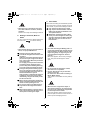
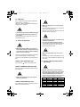
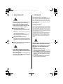
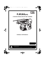
PJR265_CE.book 1 ページ 2010年10月13日 水曜日 午後4時51分 PJR265(CE) CORDLESS BRUSHLESS ROTARY HAMMER ORIGINAL USER MANUAL ENGLISH Original instructions WARNING BEFORE USING THIS TOOL, STUDY THIS MANUAL TO ENSURE SAFETY WARNING AND INSTRUCTIONS. KEEP THESE INSTRUCTIONS WITH THE TOOL FOR FUTURE REFERENCE. PJR265_CE.book 2 ページ 2010年10月13日 水曜日 午後4時51分 Fig.B 1 4 5 2 3 11 6 12 7 25 Fig.C 10 9 8 Fig.D 18 19 20 13 16 14 21 15 Fig.E 24 22 23 17 13 16 2 1 Fig.F 2 PJR265_CE.book 3 ページ 2010年10月13日 水曜日 午後4時51分 Fig.G Fig.H 7 20 Fig.I Fig.J 20 20 Fig.K Fig.M Fig.L 13 16 Fig.N 3 PJR265_CE.book 4 ページ 2010年10月13日 水曜日 午後4時51分 Fig.O 11 12 Fig.P Fig.R 1 3 Fig.Q Fig.S Fig.T 1 2 Fig.U Fig.V 2 4 PJR265_CE.book 5 ページ 2010年10月13日 水曜日 午後4時51分 Fig.X 8 10 5 Fig.W 4 Fig.Z 12 6 Fig.Y Fig.AA Fig.AB 5 PJR265_CE.book 6 ページ 2010年10月13日 水曜日 午後4時51分 DEFINITIONS OF SIGNAL WORDS WARNING: Indicates a potentially hazardous situation which, if not avoided, could result in death or serious injury. CAUTION: Indicates a potentially hazardous situation which, if not avoided, may result in minor or moderate injury. NOTE: Emphasizes essential information. INDEX 1. GENERAL POWER TOOL SAFETY WARNINGS............. 6 2. HAMMER SAFETY WARNINGS........................................ 9 3. SPECIFICATIONS AND TECHNICAL DATA .................. 11 4. BATTERY INSTRUCTIONS ............................................. 13 5. OPERATING INSTRUCTIONS......................................... 16 6. MAINTENANCE................................................................ 20 7. STORAGE ........................................................................ 20 1. GENERAL POWER TOOL SAFETY WARNINGS 1. WORK AREA SAFETY • Keep work area clean and well lit. Cluttered or dark areas invite accidents. • Do not operate power tools in explosive atmospheres, such as in the presence of flammable liquids, gases or dust. Power tools create sparks which may ignite the dust or fumes. • Keep children and bystanders away while operating a power tool. Distractions can cause you to lose control. 2. ELECRRICAL SAFETY • Power tool plugs must match the outlet. Never modify the plug in any way. Do not use any adapter plugs with earthed (grounded) power tools. Unmodified plugs and matching outlets will reduce risk of electric shock. • Avoid body contact with earthed or grounded surfaces, such as pipes, radiators, ranges and refrigerators. There is an increased risk of electric shock if your body is earthed or grounded. • Do not expose power tools to rain or wet conditions. Water entering a power tool will increase the risk of electric shock. • Do not abuse the cord. Never use the cord for carrying, pulling or unplugging the power tool. Keep cord away from heat, oil, sharp edges and moving WARNING READ ALL SAFETY WARNINGS AND ALL INSTRUCTIONS. Failure to follow the warnings and instructions may result in electric shock, fire and/or serious injury. Save all warnings and instructions for future reference. The term "power tool" in the warnings refers to your mains-operated (corded) power tool or battery-operated (cordless) power tool. 6 PJR265_CE.book 7 ページ 2010年10月13日 水曜日 午後4時51分 • Prevent unintentional starting. Ensure the switch is in the off-position before connecting to power source and/or battery pack, picking up or carrying the tool. Carrying power tools with your finger on the switch or energizing power tools that have the switch on invites accidents. • Remove any adjusting key or wrench before turning the power tool on. A wrench or a key left attached to a rotating part of the power tool may result in a personal injury. • Do not overreach. Keep proper footing and balance at all times. This enables better control of the power tool in unexpected situations. • Dress properly. Do not wear loose clothing or jewellery. Keep your hair, clothing and gloves away from moving parts. Loose clothes, jewellery or long hair can be caught in moving parts. • If devices are provided for the connection of dust extraction and collection facilities, ensure these are connected and properly used. Use of dust collection can reduce dust-related hazards. parts. Damaged or entangled cords increase the risk of electric shock. • When operating a power tool outdoors, use an extension cord suitable for outdoor use. Use of a cord suitable for outdoor use reduces the risk of electric shock. • Do not use the power tool in the rain, where water is splashing, in a wet place, or in a damp place. Using the tool in these or similar conditions will increase the risk of electric shock, dangerous malfunction, and overheating. If operating a power tool in a damp location is unavoidable, use a residual current device (RCD) protected supply. Use of an RCD reduces the risk of electric shock. 3. PERSONAL SAFETY • Stay alert, watch what you are doing and use common sense when operating a power tool. Do not use a power tool while you are tired or under the influence of drugs, alcohol or medication. A moment of inattention while operating power tools may result in serious personal injury. 4. POWER TOOL USE AND CARE • Do not force the power tool. Use the correct power tool for your application. The correct power tool will do the job better and safer at the rate for which it was designed. • Do not use the power tool if the switch does not turn it on and off. Any power tool that cannot be controlled with the switch is dangerous and must be repaired. • Disconnect the plug from the power source and/or the battery pack from the power tool before making any adjustments, changing accessories, or storing power tools. Such preventive safety measures reduce the risk of starting the power tool accidentally. • Store idle power tools out of the reach of children and do not allow persons unfamiliar with the power tool or these instructions to operate the power tool. Power tools are dangerous in the hands of untrained users. • Maintain power tools. Check for misalignment or binding of moving parts, breakage of parts and any other condition that may affect the power tool's operation. If damaged, have the power • Use personal protective equipment. Always wear eye protection. Protective equipment such as dust mask, non-skid safety shoes, hard hat, or hearing protection, hand protector used for appropriate conditions will reduce personal injuries. 7 PJR265_CE.book 8 ページ 2010年10月13日 水曜日 午後4時51分 tool repaired before use. Many accidents are caused by poorly maintained power tools. • Keep cutting tools sharp and clean. Properly maintained cutting tools with sharp cutting edges are less likely to bind and are easier to control. • Use the power tool, accessories and tool bits etc. in accordance with these instructions, taking into account the working conditions and the work to be performed. Use of the power tool for operations different from those intended could result in a hazardous situation. • DO NOT DISPOSE OF POWER TOOLS INTO HOUSEHOLD WASTE. According to the European Guideline 2002/96/EC for Waste Electrical and Electronic Equipment and its implementation into national right, power tools that are no longer usable must be collected separately and disposed of in an environmentally correct manner. 5. BATTERY TOOL USE AND CARE • DO NOT DISPOSE OF BATTERY PACKS/BATTERIES INTO FIRE OR WATER. Battery packs/batteries should be collected, recycled or disposed of in an environmental-friendly manner. • DEFFECTIVE OR DEAD OUT BATTERY PACKS/BATTERIES MUST BE RECYCLED ACCORDING TO THE GUIDELINE 91/157/EEC. • Recharge only with the charger specified by the manufacturer. A charger that is suitable for one type of battery pack may create a risk of fire when used with another type of battery pack. • Use power tools only with specifically designated battery packs. Use of any other battery packs may create a risk of injury and fire. • When battery pack is not in use, keep it away from other metal objects, like paper clips, coins, keys, nails, screws or other small metal objects, that can make a connection from one terminal to another. Shorting the battery terminals together may cause burns or a fire. • Under abusive conditions, liquid may be ejected from the battery; avoid contact. If contact accidentally occurs, flush with water. If liquid contacts eyes, additionally seek medical help. Liquid ejected from the battery may cause irritation or burns. • PROTECT THE BATTERY AGAINST HEAT, ALSO AGAINST CONTINUOUS SUN IRRADIATION AND FIRE. There is danger of explosion. • CHARGE THE BATTERY PACK IN A TEMPERATURE RANGE 5°(41F) TO 40°(104F) 6. SERVICE • Have your power tool serviced by a qualified repair person using only identical replacement parts. This will ensure that the safety of the power tool is maintained. 8 PJR265_CE.book 9 ページ 2010年10月13日 水曜日 午後4時51分 2. HAMMER SAFETY WARNINGS 7. LET THE TOOL WARM UP FOR SEVERAL MINUTES BEFORE USE In cold weather or when the tool has not been used for a long period of time, the internal lubrication in the tool might not be insufficient. In such cases, let the tool warm up for several minutes by operating it with no load. Lacking sufficient internal lubrication, the tool might not operate at full performance. 1. BE SURE TO KEEP HANDS AWAY FROM THE TRIGGER SWITCH AND DETACH THE BATTERY PACK WHEN REPLACING OR ADJUSTING THE BIT, WHEN ABNORMALITIES OCCUR, AND WHEN THE EQUIPMENT IS NOT BEING USED Leaving the Battery pack installed in these situations may cause breakdowns or damage. 8. MAKE SURE TO OPERATE THE TOOL ON A FIRM FOOTING Failure to do so may lead to serious injury. 2. HOLD TOOL BY INSULATED GRIPS WHEN PERFORMING AN OPERATION, BECAUSE THE TOOL'S BIT MAY CONTACT HIDDEN "LIVE" WIRE Contacting with a "live" wire may make exposed metal parts of the tool "electrified" and shock the operator. Failure to do so may result in serious injury. 9. MAKE SURE THERE IS NO ONE BELOW WHEN USING THE TOOL IN HIGH LOCATIONS Failure to do so may lead to serious injury of the person below. 10. HOLD THE TOOL FIRMLY WITH BOTH HANDS Failure to do so may lead to serious injury. 3. MAKE SURE THE BIT IS SECURED IN PLACE BEFORE OPERATION Failure to do so may result in serious injury. 11. KEEP HANDS AWAY FROM MOVING PARTS 4. DO NOT POINT THE TOOL AT ANYONE Personal injury may result if the tool catches an operator or anyone working near him. While working with the tool, be extremely careful not to bring hands, legs, and other body parts near the bit of the tool. 12. DO NOT LEAVE THE TOOL RUNNING Operate the tool only when hand-held. 13. DO NOT TOUCH THE BIT OR PARTS CLOSE TO THE BIT IMMEDIATELY AFTER OPERATION These parts may be extremely hot. Touching these parts may cause serious injury. 5. NEVER MODIFY THE TOOL Modifying the tool will impair performance and operating safety. Any modification may lead to serious injury and void the tool warranty. 14. USE ONLY THE AUTHORIZED BATTERY PACK Use only MAX JPL925 battery pack. If the tool is connected to a power supply other than the authorized pack, such as a rechargeable battery, a dry cell, or a storage battery for use in automobiles, the tool may be damaged, break down, overheat, or even catch on fire. Do not connect this tool to any power supply except the MAX JPL925 battery pack. 6. MAINTAIN THE TOOL IN GOOD OPERATING CONDITION (CHECK TIGHTNESS OF SCREWS BEFORE OPERATION) To secure operating safety and ensure top performance, keep the tool free of wear and damage. Under normal operation, the tool is designed to produce vibration. Due to the vibration, the screws can come loose, causing damage to the tool or serious injury. Also keep the tool's hand grip dry and clean, especially free of oil and grease. 15. TO ENSURE MAXIMUM PERFORMANCE, FULLY CHARGE THE BATTERY BEFORE USE A new battery pack or one not used for extended periods may have self-discharged and thus may need recharging to restore it to a fully charged condition. Before operating the tool, make sure to charge the Battery pack with the designated MAX Battery charger JC928. 9 PJR265_CE.book 10 ページ 2010年10月13日 水曜日 午後4時51分 16. BATTERY CHARGING PRECAUTION 13 Any objects that block the ventilation holes or Battery pack receptacle may cause electric shock or functional troubles Operate the charger free of dust or other foreign materials. 1 Use only MAX Battery charger JC928 and Battery Pack JPL925 Failure to do so may cause the Battery to overheat or catch fire leading to serious injury. 14 Handle the power cord carefully Do not carry the Battery charger by its power cord. Do not use the power cord to disconnect it from a wall socket; this will damage the cord and break the wires or cause a short circuit. Do not let the power cord contact sharp edged tools, hot materials, oil, or grease. A damaged cord must be repaired or replaced. 2 Charge the Battery from AC between 100V and 240V wall sockets Failure to do so may result in overheating, or inadequate charging possibly causing serious injury. 3 Never use a transformer 4 Never connect the Battery charger to an engine generator direct-current power supply The charger will break down or be damaged from burning. 15 Do not charge non rechargeable batteries with this charger. 16 This charger is not intended for use by children or disabled persons without supervisor. 5 Avoid charging the Battery pack in the rain, in a damp place, or where water is splashing Charging a damp or wet Battery pack will cause an electric shock or a short circuit that may lead to damage from burning and even the tool catching on fire. 17 Children should be supervised to ensure that they do not play with the charger. 18 Put a pack cap on the terminal of the Battery pack When the Battery pack is not in use, put a pack cap on its terminal to prevent short circuits. Keep it away from other metal objects, such as clips, coins, keys, nails, screws or other small metal objects, that can make a connection from one terminal to another. 6 Do not touch the power cord or plug with a wet hand or glove This may cause injury from electric shock. 7 Do not put a cloth or any other cover on the Battery charger while the Battery pack is being charged This will cause overheating and damage from burning, or the Charger may even catch fire. 19 Do not leave or store the tool in a vehicle or in direct sunlight during summer. Leaving the tool in high temperature conditions may cause the battery pack to deteriorate. 8 Keep the Battery pack and Battery charger away from heat and flames 9 Do not charge the Battery pack near flammable materials 20 Do not store a fully discharged battery pack. If a fully discharged battery pack is removed from the system and left for a long period of time, it may be-come damaged. Recharge the battery immediately when it has been discharged. 10 Charge the Battery pack in a well ventilated place Avoid charging the Battery pack where it will be in direct sunlight. 11 Charge the Battery pack in a tem-perature range of 5°C (41°F) to 40°C (104°F) 12 Avoid continual use of the Battery charger Rest the Charger for 15 minutes between charges to avoid functional trouble with the unit. 10 PJR265_CE.book 11 ページ 2010年10月13日 水曜日 午後4時51分 3. SPECIFICATIONS AND TECHNICAL DATA 1. NAME OF PARTS (See Fig. B, C and D) Fig. B 1 DEPTH GAUGE 2 SDS PLUS TOOL HOLDER 3 SIDE HANDLE 4 PACK CAP 14 TERMINAL 15 VENTILATION WINDOW CHANGEOVER LEVER 16 LATCH 5 LOCK BUTTON 17 SPECIFICATION LABEL 6 LED LAMP 18 BATTERY PACK ENTRY POINT 7 BATTERY PACK JPL925 8 CHANGEOVER SWITCH 19 LED LAMP (ORANGE) CHARGING STATUS INDICATOR LAMP 9 CONTROL PANEL 10 STATUS INDICATOR LED (RED / GREEN) 20 LED LAMP (RED / GREEN) CHARGING STATUS INDICATOR LAMP 11 ROTATIONAL DIRECTION SWITCH 21 SPECIFICATION LABEL 12 TRIGGER SWITCH (CONTINUOUSLY VARIABLE) 22 VENTILATION WINDOW 23 POWER CORD 24 CE (VDE) POWER PLUG 25 Fig. C 13 Fig. D SPECIFICATION LABEL 2. TOOL SPECIFICATIONS <Battery charger> PRODUCT NO. PJR265 PRODUCT NAME MAX lithium ion battery charger WEIGHT 3.7kg(8.1lbs.)(Battery included) PRODUCT NO. JC928(CE) HEIGHT 210mm (8-1/4") INPUT WIDTH 82mm (3-1/4") AC100-240V 50/60Hz 1.620.68A LENGTH 332mm (13-1/16") OUTPUT DC 7.2/10.8/14.4V 7A DC 18/21.6/25.2/28.8V 3.9A TOOL HOLDER SDS PLUS WEIGHT 1.6kg (3.5lbs.) VOLTAGE / BATTERY 25.2V, Li-ion Battery pack JPL925 OPERATING TEMPERATURE 5°C to 40°C (41°F to 104°F) RATED SPEED Normal mode : 0~920 min-1 Slow mode : 0~560 min-1 OPERATING HUMIDITY 80% RH or less IMPACT FREQUENCY AT RATED SPEED Normal mode : 0~4,700 min-1 Slow mode : 0~2,860 min-1 MAXIMUM DRILLING DIAMATER Concrete : 26mm (1") Steel : 13mm (1/2") Wood : 30mm (1-3/16") MOTOR Brushless DC Motor OPERATING TEMPERATURE -5°C to 40°C (14°F to 104°F) OPERATING HUMIDITY 80% RH or less 11 PJR265_CE.book 12 ページ 2010年10月13日 水曜日 午後4時51分 <Battery pack> PRODUCT NAME MAX lithium ion battery pack PRODUCT NO. JPL925 BATTERY TYPE Lithium ion battery NOMINAL VOLTAGE DC25.2 V NOMINAL CAPACITY 3.0 Ah (3,000 mAh) CHARGING TIME (USE WITH JC928(CE)) Quick charging - Approximately 35 minutes (Apprx. 90% of capacity) Full charging - Approximately 45 minutes at 25°C(77°F) (100% of capacity) ACCESSORIES Pack cap (For preventing short circuit) WEIGHT 0.9 kg (2.4lbs.) CHARGING TEMPERATURE 5°C to 40°C (41°F to 104°F) OPERATING TEMPERATURE -5°C to 40°C (14°F to 104°F) OPERATING HUMIDITY 80% RH or less BATTERY CHARGER: Use only an authorized Battery charger, MAX JC928. 3. TECHNICAL DATA 4 Overvoltage category 1 NOISE The typical A-weighted noise level determined according to EN60745-2-6: • Sound pressure level (LpA): 108dB (A) 97dB (A) • Sound power level (LWA): • Uncertainty (K): 3dB (A) PRODUCT Overvoltage category PJR265 CORD-LESS BRUSH-LESS ROTARY HAMMER Category 1 according to IEC 60664-1 JC928(CE) BATTERY CHARGER Category 2 according to IEC 60664-1 5 Pollution degree Pollution degree : degree 4 according to IEC 60664-1 (Both of PJR265 and JC928(CE)). 4. APPLICATIONS Hammer-drilling in the following materials • Concrete • Brick • Stone Wear ear protection 2 VIBRATION The vibration total value (tri-axial vector sum) determined according to EN60745-2-1: • Work mode: Drilling into metal ≤2.5m/s2 • Vibration emission: (ah, HD): • Uncertainty (K): 1.5m/s2 Drilling in the following materials • Wood • Metal 5. ABOUT PRODUCTION YEAR This product bears production number in the body. The two digits of the number from left indicates the production year. The vibration total value (tri-axial vector sum) determined according to EN60745-2-6: • Work mode: hammer-drilling into concrete, 16mm diameter and 100mm depth 18.2m/s2 • Vibration emission: (ah, HD): • Uncertainty (K): 1.5m/s2 (Example) 08826035D 3 RADIATED EMISSION 30-1000 MHZ Class B Year 2008 12 PJR265_CE.book 13 ページ 2010年10月13日 水曜日 午後4時51分 4. BATTERY INSTRUCTIONS WHEN THE ORANGE STANDBY LIGHT BLINKS 1. Charging This indicates the Battery cannot be charged. Unplug the Charger and check the charging receptacle. If there are any foreign objects, remove them with a soft dry cloth. If the orange light still blinks or there are no foreign objects, there may be a problem with the battery or charger. Return to dealer for service. WARNING • Before removing the Battery pack from the tool, set the Rotational direction switch(Fig. B.11) at middle position, and keep hands away from the Trigger switch(Fig. B.12). 3 (Fig. H) Charge the Battery pack. (1) Fully insert the Battery into the receptacle on the Charger until it sits securely on the end. (2) Charging will start automatically and will be indicated by the red charging light with beeps. 1 (Fig. E) A Pack cap(Fig. E 13) that is used to prevent short circuits must be removed from the terminal of the Battery pack. (3) Charging time is approximately 35 minutes (90% capacity). This will vary by temperature and source voltage. (Fig. F) When charging the Battery pack, remove it from the tool by pushing on its latches (Fig. F 16) from both sides while firmly holding the grip of the tool. (4) For batteries those are at low temperatures (10°C (50°F) or lower), charging time must be extended longer. When charging at low temperatures, both of the red and the orange charging light will be lit. 2 (Fig. G) Plug the charger into a wall socket (100V - 240V). The red light, a current-carrying indicator, (Fig. G 20) will flash on and off with two short (Pipi) beep sounds. 4 (Fig. I) When the battery pack has been recharged, the "red" lamp turns off and the "green" lamp blinks. The "green" LED lamp(Fig. I 20) blinks slowly and a long beep sounds for approximately 2 seconds. Now, the battery has been recharged to approximately 90% of its capacity. Quick charging takes approxi-mately 35 minutes (however, the recharging time and capacity slightly change depending on the ambient temperature and power voltage). WHEN THE ORANGE STANDBY LIGHT IS LIT When the Battery pack is hot (after continuous use or exposure to direct sunlight) the Charger will automatically switch to standby to protect the Battery. The orange standby light will be lit until the Battery's temperature lowers to a safe level, The Battery will then be charged auto-matically. (Fig. J) You can use the battery pack when quick charging is complete. However, if you leave the battery pack on the charger, recharging will continue. When the battery is fully recharged (to 100% capacity), the "green" LED lamp lights up (and a long beep sounds for approximately 2 seconds). WHEN THE BATTERY PACK IS AT LOW TEM-PERATURE When the Battery pack is at low temperature, its charging is automatically suspended until its temperature increases (higher than 5°C (41°F)), in order to protect it, even if it is set in the Charger. Leave the Battery pack at normal temperature in the room for some time, and then, charge it again. (1) (Fig. K) After you have recharged the battery pack, remove it from the charger. (2) (Fig. L) Unplug the charger power cord from the wall socket. 13 PJR265_CE.book 14 ページ 2010年10月13日 水曜日 午後4時51分 SERVICE LIFE OF BATTERY PACK If any condition described below is observed, the battery pack is at the end of its service life. Replace it with a new one. • Although the battery pack has been properly charged (fully charged), a great drop in tying time has been noticed. CAUTION • When the battery pack is fully discharged, do not leave it for a long time without recharging. If the fully discharged battery pack is removed from the system and left for a long time, the battery pack may become damaged. Recharge the battery immediately when it has been discharged. • Do not leave the battery pack on the charger. If the above is not observed, a weak current will continue to flow and the battery pack may become damaged. When recharging is complete, always remove the battery pack from the charger. WARNING Do not charge the battery pack when this happens. If the motor's rotational speed slows down, the power of the battery pack is considered to be nearly depleted. Using the tool more will cause it to overdischarge, resulting in a shortened service life of the battery pack and also in functional trouble of the tool's main body. BATTERY PACK BREAKDOWNS If the following conditions occur, bring the Battery and Charger to your dealer. • The red charging lamp does not flash when the charger plug is inserted into main power source outlet (When the Battery pack is not inserted in the charger.) • Neither the red charging lamp nor the orange standby lamp lights or flashes when the Battery pack is inserted in the charger. • The orange standby lamp does not change to the red charging lamp even after more than 1 hour. • The red charging lamp does not change from constant to flashing light even after more than 90 minutes. (except at low temperatures) CAUTION Do not use a battery pack when its service life is finished. This will cause functional trouble in the tool's main body. Also charging a battery pack that is out of service life will lead to functional trouble in the battery charger. RECYCLING A LI-ION BATTERY The MAX battery pack uses a Li-ion battery, it may be illegal to dispose of this battery into the municipal waste system. Check with your local solid waste officials for details in your area for recycling options or proper disposal. CAUTION When disposing of the battery pack, make sure to put a pack cap on its terminal (with insulating tape securing it) to prevent short circuits. 14 PJR265_CE.book 15 ページ 2010年10月13日 水曜日 午後4時51分 INDICATION OF QUICK CHARGER LAMPS Charger LED lamp Red lamp blinks. It blinks every second. Red lamp lights. It remains lit. The green lamp blinks. It blinks every second. The green lamp lights up. It remains lit. The red lamp lights up. The orange lamp lights up. They remain lit. Buzzer sound The power cord is plugged into the receptacle. Two short beeps (Pi, pi) The battery pack is mounted. One short beep (Pi) The battery has been recharged. A long beep for approx. 2 seconds (Piii...) Recharging status The charger is powered. The charger power cord is plugged into a wall socket. The battery is being recharged. Quick recharging continues. The battery has been recharged. The battery has been recharged to approx. 90% of its capacity. If you leave the battery pack on the charger, recharging will continue. Fully recharged. A long beep for approx. 2 seconds (Piii...) Battery is "fully" re- Recharged to 100% capacity. charged. — The battery is recharged with a low Protective charging current to protect the charger and battery. — If the temperature of the battery pack is too high: Battery recharging starts automatically when the tem-perature drops below the limit. If the temperature of the battery pack is too low: Place the battery pack in a room temperature location for a while, then retry recharging it. The orange lamp lights up. It blinks every second. The orange lamp blinks. It blinks quickly (0.1 sec ON and 0.1 sec OFF). Standby Not possible to recharge. Short continuous beeps for approx. 10 seconds (Pi, pi, pi, pi,...) to recharge the battery. Not possible to re- Unable The battery pack slot is contaminated, charge. or the battery pack has failed. ∗ For batteries those are at low temperatures (10°C (50°F) or lower), charging time must be extended longer. For the JC928 lithium ion battery charger (CE) "Power Supply Cord: Use UL Listed and CSA Certified detachable power supply cord, 18 AWG, two conductors, cord rated VW-1, 105°C, cord external length minimum 1.8m. One end terminates in a molded-on attachment plug with a 15 A, 125 V (NEMA 1-15P) or 15 A, 250 V (NEMA 2-15P) type configuration. Other end terminates in a molded-on connector which mates with the Power Appliance Inlet. If a flexible power supply cord is required, the appropriate cord (see below) must be used. The SP-2, SPE-2, SV, SVE, or SVT flexible power supply cord can be used." 15 PJR265_CE.book 16 ページ 2010年10月13日 水曜日 午後4時51分 5. OPERATING INSTRUCTIONS 3. How to operate the Changeover switch (Fig. P and Q) Seeing the tool as shown in the figure P, press the Changeover switch (Fig. P 11) to the right to operate the tool clockwise. Press the switch to the left to operate the tool counterclockwise. Set the switch at the middle position to lock the tool's operation. When the tool is not in use, make sure to set the switch at middle position. 1. How to mount / remove the Battery pack WARNING • Before mounting / removing the Battery pack from the tool, set the Rotational direction switch(Fig. B.11) at middle position, and keep hands away from the Trigger switch(Fig. B.12). • Before operation, make sure to check the Battery pack is securely set in the tool. Failure to do so may cause serious injury. CAUTION • Do not operate the Changeover switch during the tool is in operation. Operating the switch during the tool's operation may damage the tool. 1 (Fig. N) When mounting the Battery pack, insert the Battery pack in the tool so that the rails of the Battery and the tool fit each other. Slide the Battery pack to the end, until the click is heard. The Latches(Fig. N 16) must be returned to the original position. 4. How to use the Side handle and the Depth gauge 2 (Fig. F) When removing the Battery pack, remove it from the tool by pushing on its latches (Fig. F 16) from both sides while firmly holding the grip of the tool. WARNING • Make sure to operate the tool with holding the tool firmly with both hands, by the Side handle and the grip. • Use only the original Side handle, which is included in the package. • Before attaching / removing the Side handle or the Depth gauge, keep the fingers away from the Trigger switch, and remove the Battery pack from the tool. • When unable to attach the Side handle securely, do not use the tool. 2. How to operate the Trigger switch (continuously variable) (Fig. O) To start the tool, pull the Trigger switch (continuously variable). Release the Trigger switch to stop. The Trigger switch is continuously variable, which makes the tool speed increased by increasing pressure on the Trigger switch (vice versa). (Fig. R) The Side handle (Fig. R 3) is 360 deg. rotatable. Adjust it at the best angle by loosening and tightening the handle (Fig. S) The Depth gauge(Fig. S 1) enables adjustment of hammer-drilling depth. The Depth gauge is adjustable by loosening and tightening the Side handle (Fig. R 3) WARNING • When pulling or releasing the Trigger, the LED lamp on the Control panel (Fig. B 10) flashes (Orange) for a moment. This shows the power is on. The Depth gauge is for rough adjustment of the hammer-drilling depth. For precise depth adjustment, measure the hammer-drilling depth with a measuring equipment. 16 PJR265_CE.book 17 ページ 2010年10月13日 水曜日 午後4時51分 5. How to set and remove the SDS Plus bit to the Tool holder 7. Drilling in Metal or Wood For use in Steel or Wood material, set the lever to the for drilling. 1 Hold the tool firmly with both hands. 2 Point the bit straight to the drilling object. Do not apply excess pressure to the drilling object. Applying excess pressure may reduce working efficiency, as well as shorten the lifetime of the tool and the bit. WARNING • Before setting / removing the SDS Plus bit to the tool, keep the fingers away from the Trigger switch, and remove the Battery pack from the tool. 3 During the drilling operation, when the tool is overloaded, the tool may automatically stops operation. When this occur, release the Trigger switch and pull the bit out from the drilling object, then stop operation. Failure to do so may cause damage to the tool. HOW TO SET THE SDS PLUS BIT (Fig. T) Insert the SDS Plus bit to the Tool holder (Fig. T 2) until a click is heard. Make sure to check the bit is securely fixed by pulling the bit. When the bit is unable to be inserted at the bottom(when a click is not heard), rotate the bit a little bit and try again. HOW TO REMOVE THE SDS PLUS BIT CAUTION (Fig. U) Hold and press the Tool holder downward, then remove the bit. • (Fig. X) When the LED lamp (Fig. X 8) lights with Red color, it shows the tool is overheated and automatically stopped due to overload or continuous operation. During the LED lamp lights with Red color, the tool does not operate although the Trigger switch is pulled. Approximately one minute later, the LED lamp goes off and the tool becomes operational again. However, for the best performance of the tool, continue operation after the tool is cooled down sufficiently. (Fig. V) Prior to set the SDS Plus bit to the tool, clean the holder's end of the bit, then apply grease (Use Shell ® Alvania S2 grease. ) to the dent of the bit, as shown in the figure V. 6. How to operate the Changeover lever 4 When removing the bit from the drilling object by operating the tool counterclockwise, hold the tool with both hands, pull the bit out with operating the tool. WARNING • Do not operate the Changeover lever, when the tool is in operation. 5 To operate the tool at the best performance, when start drilling, point the bit with pulling the Trigger switch slightly (slow speed). As the drilled hole getting deep, pull the Trigger switch more to increase the speed. (Fig. W) Change the operating mode by the Changeover lever, depending on the object to drill. To change the operating mode, pressing the Lock button (Fig. W 5), then turn the Changeover lever(Fig. W 4) to drilling or hammer-drilling position. When turning to either position, make sure to check a click is heard. For use in Steel or Wood material, set the lever to the for drilling. For use in concrete, brick or stone, set the lever to the for hammer-drilling. CAUTION • When drilling in Metal or Wood, use proper bit . Especially when drilling in Steel, use proper lubricants. However, when drilling in Brass or Cast iron, do not use lubricants. 17 PJR265_CE.book 18 ページ 2010年10月13日 水曜日 午後4時51分 9. Slow mode When hammer-drilling a small diameter (smaller than 5mm) hole in Concrete, operate the tool at "Slow mode", to prevent the breakage of the bit. WARNING • When the tool is overheated, stop operation. After sufficient cool down, continue operation. Failure to do so may cause damage to the tool. 1 (Fig. X) Press the Changeover switch (Fig. X 8) and check the Status indicator LED (Fig. X 10) lights up with Green color. Then operate the tool. 2 When finish operating the tool at Slow mode, press the Changeover switch (Fig. X 8) again and check the Status indicator LED (Fig. X 10) goes off. The tool is at Normal mode. 8. Drilling in Concrete, Brick or Stone For use in Concrete, Brick or Stone material, set the lever to the for hammer-drilling. CAUTION CAUTION • Soon after mounting the Battery pack or a certain period of time after the last drill-ing/ hammer-drilling, the Status indicator LED might not lights up or might not goes off, even though the Changeover switch is pressed. When this happens, with no load, pull trigger once, then press the Changeover switch again. • When hammer-drilling in Concrete, Brick or Stone, use proper SDS Plus bit. 1 Hold the tool firmly with both hands. 2 Point the bit straight to the hammer-drilling object. If the bit is not pointed straight to the object, the bit may be caught in the drilled hole, and it makes difficult to pull the bit out from the hole. Do not apply excess pressure to the hammer-drilling object. Applying excess pressure may reduce working efficiency, as well as shorten the lifetime of the bit. WARNING • Do not operate the Changeover switch, when the tool is in operation. • Use the "Slow mode" only for ham-merdrilling in Concrete. Do not use the "Slow mode" for drilling in Wood / Metal objects. "Slow mode" is not suitable for heavy-load operation. 3 During the deep hammer-drilling operation, if the operating speed slows down, pull the bit slightly out from the hole, so that the drilled dust is ejected. If the operation is automatically stopped completely, release the Trigger switch immediately, stop operation and pull the bit out from the hole. 4 When removing the bit from the drilling object, hold the tool with both hands, pull the bit out with operating the tool. 5 Do not pour water to the drilling hole. It may make the bit caught in the drilled hole. WARNING • When the bit is caught in the object, or when hammer-drilling in an inclined angle, the tool may be automatically stopped due to overload preventive clutch. When this happens, before removing the bit from the object, remove the bit from the tool, in order to prevent damaging the tool. 6 When hammer-drilling in the thin object, apply a plywood panel to the object, in order to prevent cracking the object. 18 PJR265_CE.book 19 ページ 2010年10月13日 水曜日 午後4時51分 10. LED lamp (Fig. Y) When the Trigger switch is pulled, the LED lamp (Fig. Y 6) lights up. When 10 ~ 15seconds past after releasing the Trigger switch, it goes off. WARNING • When operating the tool, do not hold the Dust cup. If the tool is held at the Dust cup, it may drop off and cause serious injury. Make sure to hold the tool with both hands, at the Side handle and the grip. WARNING • Do not directly look in the LED lamp's light. • Do not point the LED lamp's light to anyone's eyes. Pointing the LED lamp's light to the eyes may cause serious injury. WARNING • Use the Dust cup only for Concrete, Brick and Stone applications. Do not use for Metal and other objects. Using the Dust cup for Metal and other objects may damage the Dust cup, due to the hot ground metal pieces or like. 11. Dust cup (Optional) WARNING • When attaching the Dust cup to the tool, keep hands and fingers away from the Trigger switch, and make sure that the Battery pack is not set in the tool. CAUTION • When storing the Dust cup, do not compress it. If the Dust cup is kept compressed for a long time, it may not be unable to recover the original shape. The Dust cup reduces falling down of the dusts when overhead drilling / hammer-drilling. The Dust cup is available as an optional accessory. 12. Drilling / Hammer-drilling times per charge HOW TO SET THE DUST CUP (Fig. Z) Fit the portion to the side handle. HOW TO REMOVE THE DUST CUP (Fig. AA) Hold near the bottom of the Dust cup, then take it out. CAUTION • Regarding the drilling / hammer-drilling times per charge, it depends on the condition of the Battery pack, hardness of the material and the performance of the bit. The following chart is based on the brand-new battery and hammer-drilling in Concrete. CAUTION • Before removing the Dust cup, eject the dust in the Dust cup. Mode Slow Normal Normal Normal Normal Normal HOW TO USE THE DUST CUP (Fig. AB) Fit the front end of the Dist cup to the object, then operate the tool. 19 Bit diameter φ4.3mm φ6.5mm φ12.5mm φ14.5mm φ18mm φ26mm Depth 30mm 30mm 30mm 100mm 60mm 60mm Drilling times Apprx. 221 Apprx. 184 Apprx. 105 Apprx. 20 Apprx. 26 Apprx. 7 PJR265_CE.book 20 ページ 2010年10月13日 水曜日 午後4時51分 6. MAINTENANCE 7. STORAGE Do not store the tool in a cold weather envi-ronment. Keep the tool in a warm area. When not in use, the tool should be stored in a warm and dry place. Keep out of reach of children. All quality tools will eventually require servicing or replacement of parts because of wear from normal use. WARNING • Before inspecting the tool, make sure that the Battery pack is not set in the tool. Failure to do so may cause serious injury. • Before inspecting the Battery charger JC928, make sure that the Charger is disconnected from the power supply. STORE THE TOOL When you have finished drilling / hamer-drilling work or when the tool will not be used for a while, remove the battery pack from the tool. Tool, attachments and accessories should be stored in a well-ventilated dry place where the temperature will not exceed 40°C (104°F). The battery pack, with a pack cap installed on the pack's terminal to prevent short circuits, should be stored in a well-ventilated dry place where the temperature will not exceed 30°C (86°F). 1 Regularly inspect the tool In order to maintain the performance of the tool, periodically clean up and inspect the tool. Examine the screws regularly to make sure they are securely tightened. Incomplete tightening may result in an accident or breakage. If a screw is loose, retighten it completely. 2 Do not lubricate the equipment Absolutely do not lubricate this equipment. Applying lubrication will remove the grease inside of the tool, and cause problem on the tool. CAUTION 3 Do not soak the tool to any liquid. Do not put any liquid in the tool. WHEN STORING THE BATTERY PACK FOR A LONGER TIME THAN 6 MONTHS WITHOUT USE, TO KEEP THE PERFORMANCE OF THE BATTERY PACK, FOLLOW THESE INSTRUCTIONS ; • Fully recharge before storage. • Put a Pack cap on the Battery pack's ter-minal to prevent short circuits. • Store the Battery pack in a well-ventilated dry place where the temperature will not be less than -20°C(-4°F) and will not exceed 30°C (86°F). • Do not store the Battery pack in a place where is under direct sunshine. CAUTION • (Fig. X) When the Status indicator LED blinks with Green color, it shows that the after-servicing by MAX authorized distributor is recommended. When this happens after releasing the Trigger switch, contact MAX authorized distributor for the afterservice. 20 PJR265_CE.book 21 ページ 2010年10月13日 水曜日 午後4時51分 PJR265(CE) EXPOLDED VIEW AND SPARE PARTS LIST 8 4 2 1 5 16 6 19 17 18 11 22 20 3 23 7 24 13 C 68 14 21 12 31 15 A A 25 26 30 35 43 34 28 42 41 40 39 38 B 33 32 27 29 37 36 53 49 44 B 45 69 54 50 55 60 54 52 61 59 58 57 48 56 62 21 47 74 51 66 67 70 46 C 63 9 10 56 73 71 65 72 64 PJR265_CE.book 22 ページ 2010年10月13日 水曜日 午後4時51分 PJR265 (CE) ITEM NO. 1 PART NO. MATERIAL ENGLISH DEUTSCH PJ70257 PA, Rubber sponge, PET motor housing set (L& R) (CE) 2 AA05590 Steel TAP tight(B)4X20 CF +bind 3 PJ10922 PC LED lens 4 LL11730 Steel ball bearings 608DD 5 PJ10948 CR Rubber sponge seal 6 PJ10910 ABS change lever 7 PJ10921 Steel spring 8 PJ70077 PA, PBT, Copper, Stainless steal trigger SW lever 9 PJ13022 PET Rating Label(CE) 10 PJ13023 PET Panel Label(CE) 11 PJ70091 ABS, Silicon Rubber main circuit board unit 12 PJ70084 PBT, phosphor bronze battery connector unit 13 AA21176 Steel Phillips pan head screw 5X8 mec 14 YU39103 Huse huse 31500001 RT0 15 CC41303 Steel hex nut 1-5 16 PJ70086 Steel, Aluminium, Sillicon main printed circuit board unit 17 PJ70087 Steal, PA, Copper, brass stator unit 18 PJ70095 Steel, PA, Magnet rotor assy 19 AA22105 Steel oval counter-sunk screw 4×10 20 HH14028 NBR Rubber O-ring as 568-028 21 HH22009 NBR Rubber oil seal 009 22 PJ70070 Aluminum, Steel inner housing unit felt 23 PJ10920 felt 24 HH11505 Sillicon Rubber O-ring, Type 4, C P65 25 EE39842 Steel special plain washer 28.6X33X1 26 BB40839 Steel hex socket head cap srew M46X16 mec 27 PJ80010 Steel inner shaft unit 28 KK83015 Steel conical coil spring 3015 29 PJ10887 Steel clatch 30 JJ51603 Steel washer C 14 31 EE39844 Steel special plain washer 12.1X18X1 32 PJ10884 Steel piston pin 33 PJ10883 Aluminium piston 34 HH19613 Fluororubber special O-ring,type 4, D 3X16 35 PJ10882 Steel ram 36 JJ80602 Steel retainer 25 37 PJ10881 Steel holder sleeve 38 HH14166 NBR Rubber O-ring AS 568-204 39 HH19914 NBR Rubber special O-ring 4.5X16.2 40 PJ10880 Steel hammer folder A 41 HH11111 NBR Rubber O-ring type 1A P14 42 PJ10879 Steel second Hammer 43 PJ10878 Steel hammer folder B 44 PJ70082 Steel, NBR Rubber bushing unit 45 PJ10877 Steel cylinder head 46 PJ10885 Steel second gear 47 KK29022 Steel compression spring 9022 48 EE39843 Steel special plain washer 32.5X40X2 49 PJ70078 cylinder assy 50 JJ51604 Steel C-ring 32 51 LL11729 Steel ball bearings 606VV 52 PJ70256 PA GEAR HOUSING ASSY(CE) 53 AA35601 Steel CROSS RECESSED TRUSS SCREW 1, 5X50 CF 54 PJ10960 PET logotype label 55 PJ13021 PET name label (CE) 56 PJ70072 CHANGE LEVER ASSY 57 HH11106 NBR Rubber O-ring 1A P16 58 KK83014 Steel conical coil spring 3014 59 PJ10874 Steel holder washer 60 LL71602 Steel steel ball 7 22 FRANÇAIS ITALIANO ESPAÑOL PJR265_CE.book 23 ページ 2010年10月13日 水曜日 午後4時51分 PJR265 (CE) ITEM NO. 61 PART NO. MATERIAL ENGLISH PJ10873 Steel ball holder 62 PJ10872 PA retainer 63 PJ10871 NBR Rubber front cap 64 PJ10892 ABS push button 65 KK29021 Steel compression spring 9021 66 PJ70098 PAޔSteel change lever unit 67 PJ70073 SIDE HANDLE ASSY 68 PJ10907 phosphor bronze relay terminal 69 EE39841 Steel special plain washer 6.2X20X1 70 BB71328 Steel hex bolt 8X90 71 CC42513 Steel hex nut type 2, M8 CF 72 PJ10900 PA side handle 73 PJ10901 PA side handle mount 74 PJ10947 Steel depth gauge DEUTSCH 23 FRANÇAIS ITALIANO ESPAÑOL PJR265_CE.book 24 ページ 2010年10月13日 水曜日 午後4時51分 PJR265 EC DECLARATION OF CONFORMITY We hereby declare that the product titled in this instruction manual conforms to the essential health and safety requirements of EC Directives as below. Directive :Machinery Directive 2006/42/EC EMC Directive 2004/108/EC Manufacturer :MAX CO., LTD. 1848, Kawai, Tamamura-machi, Sawa-gun, Gunma, 370-1117 Japan This product has been evaluated for conformity with the above directives using the following European standards. Machinery Directive: EN ISO 12100-1:2003 + A1:2009, EN ISO 12100-2:2003 + A1:2009, EN ISO 14121-1:2007, EN 60745-1:2009, EN 60745-2-2:2004 EMC Directive: EMI :EN 61000-6-3:2007 EMS :EN 61000-6-1:2007, EN 61000-4-2:2009 EN 61000-4-3:2006 + A1:2008, EN 61000-4-8:1993 + A1:2001 Title Address :General Manager, Quality Assurance Department :1848, Kawai, Tamamura-machi, Sawa-gun, Gunma, 370-1117 Japan Authorized complier :MAX EUROPE BV / President in the community Camerastraat 19,1322 BB Almere, The Netherlands EG KONFORMITÄTSERKLÄRUNG Wir erklären hiermit, dass das in dieser Bedienungsanleitung beschriebene Produkt mit den maßgeblichen Gesundheits- und Sicherheitsvorschriften der EG-Richtlinien konform ist, wie nachstehend beschrieben. Richtlinie :Maschinenrichtlinie 2006/42/EC EMC-Richtlinie 2004/108/EC Hersteller :MAX CO., LTD. 1848, Kawai, Tamamura-machi, Sawa-gun, Gunma, 370-1117 Japan Dieses Produkt wurde auf Konformität mit den obigen Richtlinien unter Einhaltung der folgenden europäischen Normen geprüft. Maschinenrichtlinie: EN ISO 12100-1:2003 + A1:2009, EN ISO 12100-2:2003 + A1:2009, EN ISO 14121-1:2007, EN 60745-1:2009, EN 60745-2-2:2004 EMC-Richtlinie: EMI :EN 61000-6-3:2007 EMS :EN 61000-6-1:2007, EN 61000-4-2:2009 EN 61000-4-3:2006 + A1:2008, EN 61000-4-8:1993 + A1:2001 Position Adresse :Generaldirektor,Abteilung für Qualitätssicherung :1848, Kawai, Tamamura-machi, Sawa-gun, Gunma, 370-1117 Japan Autorisierter Entsorger: MAX.EUROPE BV/Präsident in der Gemeinschaft Camerastraat 19, 1322 BB Almere, Holland DÉCLARATION DE CONFORMITÉ CE Nous déclarons par la présente que le produit du titre de ce manuel d’ instructions est conforme aux exigences essentielles de santé et de sécurité des Directives CE décrites ci-dessous. Directive :Directive de Mécanique 2006/42/CE Directive EMC 2004/108/CE Fabricant :MAX CO., LTD. 1848, Kawai, Tamamura-machi, Sawa-gun, Gunma, 370-1117 Japan Ce produit a été évalué pour sa conformité aux directives ci-dessus en utilisant les standards Européens suivants. Directive de Mécanique: EN ISO 12100-1:2003 + A1:2009, EN ISO 12100-2:2003 + A1:2009, EN ISO 14121-1:2007, EN 60745-1:2009, EN 60745-2-2:2004 Directive EMC: EMI :EN 61000-6-3:2007 EMS :EN 61000-6-1:2007, EN 61000-4-2:2009 EN 61000-4-3:2006 + A1:2008, EN 61000-4-8:1993 + A1:2001 Titre Adresse :Directeur Général, Département Assurance de Qualité :1848, Kawai, Tamamura-machi, Sawa-gun, Gunma, 370-1117 Japan Agent de conformité agréé:MAXEUROPE BV/Président dans la communauté Camerastraat 19, 1322 BB Almere, Pays-Bas DICHIARAZIONE DI CONFORMITÀ CE Si dichiara qui che il prodotto riferito in questo manuale di istruzioni risulta conforme ai requisiti di base concernenti la salute e la sicurezza, espressi dalle direttive CE, come riportato di seguito. Direttiva :Direttiva Macchine 2006/42/CE Direttiva EMC 2004/108/CE Produttore :MAX CO., LTD. 1848, Kawai, Tamamura-machi, Sawa-gun, Gunma, 370-1117 Japan Questo prodotto è stato valutato per la conformità con le succitate direttive, secondo i seguenti standard europei. Direttiva Macchine: EN ISO 12100-1:2003 + A1:2009, EN ISO 12100-2:2003 + A1:2009, EN ISO 14121-1:2007, EN 60745-1:2009, EN 60745-2-2:2004 Direttiva EMC: EMI :EN 61000-6-3:2007 EMS :EN 61000-6-1:2007, EN 61000-4-2:2009 EN 61000-4-3:2006 + A1:2008, EN 61000-4-8:1993 + A1:2001 Titolo Indirizzo :Direttore generale,Dipartimento controllo qualità :1848, Kawai, Tamamura-machi, Sawa-gun, Gunma, 370-1117 Giappone Sede in Europa :MAX.EUROPE BV/Presidente della società MAX.EUROPE Camerastraat 19,1322 BB Almere, Oland DECLARACIÓN EC DE CONFORMIDAD Por este medio declaramos que el producto mencionado en este manual de instrucciones se encuentra en conformidad con los requerimientos de salud y de seguridad esenciales de las Directivas CE. Directiva : Directiva sobre Maquinaria 2006/42/CE Directiva EMC 2004/108/CE Fabricante :MAX CO., LTD. 1848, Kawai, Tamamura-machi, Sawa-gun, Gunma, 370-1117 Japan Este producto ha sido evaluado en conformidad con las directivas antes mencionadas usando los estándares de Europa. Directiva sobre maquinaria: EN ISO 12100-1:2003 + A1:2009, EN ISO 12100-2:2003 + A1:2009, EN ISO 14121-1:2007, EN 60745-1:2009, EN 60745-2-2:2004 Directiva EMC: EMI :EN 61000-6-3:2007 EMS :EN 61000-6-1:2007, EN 61000-4-2:2009 EN 61000-4-3:2006 + A1:2008, EN 61000-4-8:1993 + A1:2001 Título :Gerente general,Departamento de aseguramiento de calidad Dirección:1848, Kawai, Tamamura-machi, Sawa-gun, Gunma, 370-1117 Japan Complier autorizado:MAX.EUROPE BV/Presidente de la comunidad Camerastraat 19,1322 BB Almere, Holanda