1
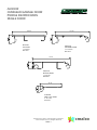
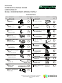
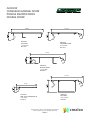
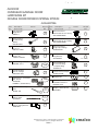
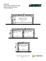
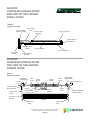
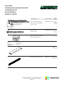
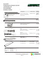
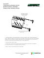
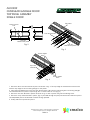
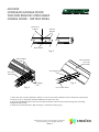
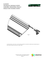
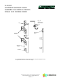
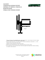
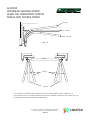
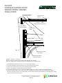
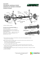
.crealco
ALDOOR
ALDOOR
OVERHEAD GARAGE DOOR
PRODUCT MANUAL
Disclaimer: The right to make alterations is reserved
© 2013 Wispeco (Pty) Ltd, All Rights Reserved
Revision: October 2013
.crealco
ALDOOR
Index
Legal Disclaimer
Profile Identification – Single Door
Hardware Kit Tension Spring System
Profile Identification – Double Door
Hardware Kit Torsion Spring System
Bolt Bag Hardware Identification
Head Room & Reveal
Side View of Mechanism Single and Double Door
Hardware Kit Single Door
Hardware Kit Double Door
Bottom Panel Assembly Single and Double Door
Top Panel Assembly Single Door
Tow Arm Bracket Attachment Double Door – Top Box Panel
Assembly Remaining Panels Single and Double Door
Assembly the Vertical Tracks Single and Double Door
Setting up Vertical Tracks & Bottom Panel Single and Double Door
Side Seal Holders Single and Double Door
Top Jambs Single and Double Door
Place Remaining Panels in Track Single and Double Door
Setting up Horizontal Tracks Single and Double Door
Align the Horizontal Tracks Single and Double Door
Tension Spring Assembly Single Door
Torsion Tube Assembly Double Door
Winding Up Torsion Springs Double Door
3
4
5
6
7
8
9
10
11
12
13
14
15
16
17
18
19
20
21
22
23
24-25
26
27
This manual must be read in conjunction with the Installation, Cleaning and Maintenance Document,
BEE Certificates and the Performance Certificates for the relevant system. The manual must also be
used in conjunction with the design and cutting list from the latest version of StarFront.
Disclaimer: The right to make alterations is reserved
© 2012 Wispeco (Pty) Ltd, All Rights Reserved
PAGE 2
.crealco
ALDOOR
LEGAL DISCLAIMER
All information, recommendations or advice contained in this documentation
is given in good faith to the best of Wispeco’s knowledge and is based on
current procedures in effect.
Since the actual use of this documentation by the user is beyond the control of
Wispeco, such use is within the exclusive responsibility of the user. Wispeco
cannot be held responsible for any loss incurred through incorrect or faulty use
of this documentation.
Great care has been taken to ensure that the information provided is correct.
Wispeco will accept no responsibility for any errors and/or omissions, which may
have inadvertently occurred.
All mechanical joints must be sealed with a Wispeco approved joint sealer.
Laminated glass must not stand in water.
All drawings in the Wispeco Documentation are shown NOT to scale.
Wispeco cannot accept responsibility for the use of standard products since
Wispeco does not know where these products are being installed.
The use of anti-magnetic stainless steel screws and pop rivets is recommended
to reduce galvanic corrosion in harsh environments.
The hardware recommended in this documentation is suitable for use in most
atmospheric environments. When hardware is used in severe costal environments
the manufacturer of the hardware must be consulted.
Fixing lugs on frames must be positioned as per the user manual and used in
accordance to the AAAMSA specifications. When profiles are screwed together
the screw centers must also be according to the user manual.
All glass used within Wispeco products must comply with SAGGA regulations.
All glazing above 10m from ground level must be signed off by a competent person
(Glazing) in accordance with the national building regulations
By continuing to use this documentation you acknowledge that you
understand and accept the legal disclaimer.
Disclaimer: The right to make alterations is reserved
© 2012 Wispeco (Pty) Ltd, All Rights Reserved
PAGE 3
ALDOOR
OVERHEAD GARAGE DOOR
PROFILE IDENTIFICATION
SINGLE DOOR
155.50
157.00
ALDOOR
TOP PANEL
1 at 2.5m
W31813
ALDOOR
STANDARD PANEL
13 at 2.5m
W31815
172.50
ALDOOR
BOTTOM PANEL
1 at 2.5m
W55586
59.46
ALDOOR
SIDE & TOP JAMB
3 at 2.5m
W32101
Disclaimer: The right to make alterations is reserved
© 2012 Wispeco (Pty) Ltd, All Rights Reserved
PAGE 4
.crealco
ALDOOR
OVERHEAD GARAGE DOOR
HARDWARE KIT
SINGLE DOOR-TENSION SPRING SYSTEM
ALDHWKITSGL
Item
No.
1
2
3
4
Description
Stock Code
Picture
Top Roller Brkt Single Door
BRKTOP-1
Nylon Roller 2”
11 Ball-Heavy
(White)
ROLLER-2N10
Vert Track Brkt “L” No J1
BRKLJ01-VTRAK
Lift Cable 3.2*3800
Tension Sp
CABLE-L TENS213
5
Sect Door Sfty CableTension Sp
CABLE-SFTYTENS
6
3” Pulley-Plastic
+ Fork-Sprg
PULLEY3P-SPRG
7
3” Pulley-Plastic
Track Mount for Wispeco
AlDoor
Pulley3P ALDTRAK
8
Anchor Bracket-Spring
Horizontal T Rack
BRKANCHR-SPRG
9
10
11
Wispeco AlDoor Top
Seal
ALSEAL TOP
Wispeco AlDoor
Bottom Seal
ALSEALBOT
Aluminium Door
Bottom Lifting Bracket
ALBRKTBOT
Qty per
Box
Item
No.
12
2
13
32
14
4
15
1
16
1
17
2
18
2
19
2
20
7.5
Meters
2.5
Description
Stock Code
Chain Hooks
“S” and “W” Types
Qty per
Box
1
Aluminium Door
Tow Arm Attach Bracket
ALTOWBRKT
1
Aluminium Door
Roller Insert Kit LH 15/bag
ALROLINSERTLHKIT
1
Aluminium Door
Roller Insert Kit RH 15/bag
ALROLINSERTRHKIT
1
Aluminium Door
Hinge Clip 42/bag
ALHINGEKIT
1
Aluminium Door
Flag Bracket
ALFLAGBRKT
1
(Pair- LH &RH)
Track Fastener &
Accessories Bag
Complete Bag
4FKTRAK-01
Pop Rivet Kit
4.8mmx12mm 50/pkt
4FRP4812ASFL
Wall Fastener Bag
4FKWALL-01
21
Manuals & Labels
Installation Manual
MANUAL-09AL
22
Wispeco Silver Sticker
ALSTICKER
(Meters)
Picture
1
1
1
Manual
Manual
WISPECO
1
1
2
Disclaimer: The right to make alterations is reserved
© 2012 Wispeco (Pty) Ltd, All Rights Reserved
PAGE 5
.crealco
ALDOOR
OVERHEAD GARAGE DOOR
PROFILE IDENTIFICATION
DOUBLE DOOR
155.50
157.00
ALDOOR
TOP PANEL
1 at 4.94m
W31813
ALDOOR
STANDARD PANEL
6 at 4.94m
W31815
172.50
ALDOOR
BOTTOM PANEL
1 at 4.94m
W55586
157.00
59.46
ALDOOR
H/D PANEL
7 at 4.94m
W55593
ALDOOR
SIDE & TOP JAMB (BLACK)
4 at 2.5m
W32101
Disclaimer: The right to make alterations is reserved
© 2012 Wispeco (Pty) Ltd, All Rights Reserved
PAGE 6
.crealco
ALDOOR
OVERHEAD GARAGE DOOR
HARDWARE KIT
DOUBLE DOOR-TORSION SPRING SYSTEM
ALDHWKITDBL
Item
No.
1
2
3
4
5
6
7
8
9
Description
Stock Code
Top Roller Brkt Single Door
BRKTOP-1
Nylon Roller 2”
11 Ball-Heavy
(White)
ROLLER-2N10
Vert Track Brkt “L” No J1
BRKLJ01-VTRAK
Lift Cable 3.2*3800
Tension Sp
CABLE-L TORS213
Side Bearing - EBF338
BRGSIDE 338-1
Centre Bearing
338-11 Gauge
BRGCNTR 338-1
Cable Drum - Standard
Size: 400-8
DRUM408/
LHS&RHS - (Red & Black)
Wispeco AlDoor Top
Seal
ALSEAL TOP
Wispeco AlDoor
Bottom Seal
ALSEALBOT
10 Aluminium Door
Bottom Lifting Bracket
ALBRKTBOT
Picture
Qty per
Box
2
Item
No.
Description
Stock Code
1
Aluminium Door
Roller Insert Kit RH 15/bag
ALROLINSERTRHKIT
1
32
4
15 Aluminium Door
Hinge Clip 70/bag
ALHINGEKIT-D
1
16
17
1 Pair
18
19
1 Pair
10
Qty per
Box
13 Aluminium Door
Roller Insert Kit LH 15/bag
ALROLINSERTLHKIT
14
1
Picture
20
21
Meters
1
Aluminium Door
Flag Bracket
ALFLAGBRKT
1
(Pair- LH &RH)
Track Fastener &
Accessories Bag
Complete Bag
4FKTRAK-02
Pop Rivet Kit
4.8mmx12mm 50/pkt
4FRP4812ASFL
Wall Fastener Bag
4FKWALL-02
Manuals & Labels
Installation Manual
MANUAL-09AL
Wispeco Silver Sticker
ALSTICKER
1
1
1
Manual
Manual
W IS PECO
1
1
5
Meters
2
Disclaimer: The right to make alterations is reserved
© 2012 Wispeco (Pty) Ltd, All Rights Reserved
PAGE 7
.crealco
ALDOOR
OVERHEAD GARAGE DOOR
BOLT BAG
HARDWARE IDENTIFICATION
Bag 4FKTRAK-01
s
Qty
Description
Where Used
8x
8x
16x
16x
12x
4x
8x
2x
2x
M8 x 16 Bolts
M8 Nuts
M5 Pan Head
M5 Nuts
M8 Washers
Plate
8x30mm Wood Screws
S-Hook
Chain
Pg 19
Pg 19
Pg 11,13
Pg 11,13
Pg 19
Pg 19
Pg 17
Pg 19
Pg 19
Bag 4FKTRAK-02
Qty
Description
Where Used
2x
8x
10x
16x
16x
10x
10x
M8 x 40 Bolts
M8 x 16 Bolts
M5 Nuts
M8 Pan Head
M5 Nuts
M8 Washers
8x30mm Wood Screws
Pg 19
Pg 19
Pg 19
Pg 11,13
Pg 11,13
Pg 19
Pg 17
Bag 4FKWALL-01
Qty
Description
4x
8x60mm Wood Screws Pg 14
11x
8x90mm Wood Screws Pg 13
15x
8x50mm Plugs
Where Used
Pg 13,14
Bag 4FKWALL-02
Qty
Description
4x
8x60mm Wood Screws Pg 14
18x
8x90mm Wood Screws Pg 13
24x
8x50mm Plugs
Where Used
Pg 13,14
Disclaimer: The right to make alterations is reserved
© 2012 Wispeco (Pty) Ltd, All Rights Reserved
PAGE 8
.crealco
ALDOOR
OVERHEAD GARAGE DOOR
HEAD ROOM & REVEAL
* AS SEEN FROM INSIDE
350.0
350.0
Double Door with motor
Headroom min 485mm
Side reveal min 350mm
with 12” track
4880.0
Single Door with motor
Headroom min 385mm
250.0 Side reveal min 250mm
with 12” track
350.0
Single Door with motor
Headroom min 385mm
Side reveal min 350mm
with 12” track
2440.0
250.0
250.0
2440.0
Single Door with motor
Headroom min 385mm 250.0
Side reveal min 250mm
with 12” track
2440.0
Disclaimer: The right to make alterations is reserved
© 2012 Wispeco (Pty) Ltd, All Rights Reserved
PAGE 9
.crealco
ALDOOR
OVERHEAD GARAGE DOOR
SIDE VIEW OF MECHANISM
SINGLE DOOR
Tension
Spring Assembly
Cable Clamp
(Punched strip)
Door Lifting
Cable
Spring Pulley
(Moving)
“S” Hook & Chain
Spring Anchor
Bracket
Spring Safety
Cable
Tension Spring
Horizontal Track
Track Pulley
(Fixed)
‘Flag’ Header
Bracket
ALDOOR
OVERHEAD GARAGE DOOR
SIDE VIEW OF MECHANISM
DOUBLE DOOR
Tension
Spring Assembly
Red (LHS)
Cable Drum
+/-3mm
Left Hand Side
Bearing Plate
Horizontal
Track
Red
Cone
Torsion
Spring
Torsion
Spring
Spring
Identification Through
Colour Code Bolts
Top Roller
Bracket
Black
Cone
Torsion
Tube
Centre
Bearing
Black (RHS)
Cable Drum
75mm Minimum
Right Hand Side
Bearing Plate
Top Panel
INSIDE
Vertical
Track
Vertical
Track
Disclaimer: The right to make alterations is reserved
© 2012 Wispeco (Pty) Ltd, All Rights Reserved
PAGE 10
.crealco
ALDOOR
OVERHEAD GARAGE DOOR
HARDWARE KIT
ALDHWKITSGL
SINGLE DOOR
Description
Horizontal T rack
Colour Code.
Stock Code
Qty
254 mm Radius Double
Horizontal Track Assembly
Colour Code
4 TRAKHZ10-240-S
Pair
Vertical T rack
Colour Code
4 TRAKVT2035-045
Pair
Horizontal Angle
Colour Code.
Colour Code.
Hardware Box for
ALDHWKITSGL
Wispeco Single Size ALDoor.
Tension Spring System
1
One Profile Kit Single Door
Top
-1
Jamb Seal - 2
Standard -13
Top Seal - 1
Bottom -1
3m length Timber
ALDTIMJAMBSGL
3
65kg Tension Springs - RED
4 SPR065-213 TENS
2
Disclaimer: The right to make alterations is reserved
© 2012 Wispeco (Pty) Ltd, All Rights Reserved
PAGE 11
.crealco
ALDOOR
OVERHEAD GARAGE DOOR
HARDWARE KIT
ALDHWKITDBL
DOUBLE DOOR
Description
Horizontal T rack
Colour Code.
Stock Code
Qty
254 mm Radius Double
Horizontal Track Assembly
Colour Code
4 TRAKHZ10-240-D
Pair
Vertical T rack
Colour Code
4 TRAKVT2035-045
Pair
Horizontal Angle
Colour Code.
Colour Code.
ALDHWKITDBL
Hardware Box for
Wispeco Double size ALDoor.
Torsion Spring System
Torsion Springs
Cone Colour
"Red"
LHS of Door
Spring Colour Code Band
Cone Colour
"Black"
RHS of Door
1
"RED"
Cone - LHS of Door
Spring Colour: ORANGE
4 SPR 060 - 213 LH
"BLACK"
Cone - RHS of Door
Spring Colour: YELLOW
4 SPR 060 - 213 RH
1
1
Torsion Tube
Length: 5200 mm
4 TORSTUBE 5200-15
1
3m length Timber
ALDTIMJAMBDBL
1
3m length Timber
ALDTIMJAMBSGL
2
One Profile Kit Single Door
Top
-1
Side Jamb Seal - 2
Standard - 6
Top Seal
-2
Bottom - 1
Box Panel
-7
Disclaimer: The right to make alterations is reserved
© 2012 Wispeco (Pty) Ltd, All Rights Reserved
PAGE 12
.crealco
ALDOOR
OVERHEAD GARAGE DOOR
BOTTOM PANEL ASSEMBLY
SINGLE AND DOUBLE DOOR
Top edge of bracket
flush with mounting
flange of panel
Fig. 1
Right hand side Roller
Insert shown
1. Attach the bottom corner lifting brackets to the panel as shown in Fig.1. Position the bracket so
that the side tab is against the door panel & the top edge of the bracket is flush with mounting flange.
Using the holes in the bracket as guides, drill through the mounting flanges on the door panel and
then attach the brackets with the supplied 4.8mm x 15mm 50/pkt rivets.
Fig. 8
2. Slide the bottom seal into place.
3. Firmly push the roller insert into place as shown. The roller inserts are handed, and marked “L”
for the left hand side & “R” for the right hand side of the door.
4. Note “R” and “L” is looked at the door from the inside.
Disclaimer: The right to make alterations is reserved
© 2012 Wispeco (Pty) Ltd, All Rights Reserved
PAGE 13
.crealco
ALDOOR
OVERHEAD GARAGE DOOR
TOP PANEL ASSEMBLY
SINGLE DOOR
Top Panel
Panel Center
Line
Fig. 8
Tow arm bracket
Tow arm
attachment plate
Tow arm
attachment plate
Fig. 2
Fig. 3
These edges
flush
Top roller
bracket
Fig. 4
These edges
flush
1 Place the door tow arm bracket in place as shown in fig. 2. The top edge of the bracket must be flush
with the top edge of the mounting flange on the panel.
2 Using the pre-drilled holes in the Tow arm attach plate, drill 6 xmm holes through the mounting flanges
and rivit the bracket in place only through the 4 corner holes for now. (Fig. 3)
3 Place the tow arm bracket in place as shown in fig. 3. Rivit in place using the remaining holes.
4 Place the 2 top roller brackets in place, (Fig. 4) and drill through the pre-punched holes and rivit in place.
The adjustable part of the bracket must be facing upwards.
5 Finally, slide the top seal into place.
Disclaimer: The right to make alterations is reserved
© 2012 Wispeco (Pty) Ltd, All Rights Reserved
PAGE 14
.crealco
ALDOOR
OVERHEAD GARAGE DOOR
TOW ARM BRACKET ATTACHMENT
DOUBLE DOOR - TOP BOX PANEL
Center line
of Panel
Tow Arm
Bracket
Brace Panel
Fig. 5
These edges
flush
Second Panel
from Top
(Box Panel)
Tow arm bracket
Top roller
bracket
Fig. 4
Fig. 6
These edges
flush
4.8 x 15mm Rivits
1 Place the door tow arm bracket in place on one of the 4 brace panels on the center line of the panel,
as shown in fig. 5. This panel will be installed second from the top.
2 Using the pre-drilled holes in the Tow arm attach bracket, drill 3 x 5mm holes through the mounting
flanges and the panel.
3 Rivet the tow arm bracket in place using 3 x 4.8x15mm rivets. (fig. 6)
Disclaimer: The right to make alterations is reserved
© 2012 Wispeco (Pty) Ltd, All Rights Reserved
PAGE 15
.crealco
ALDOOR
OVERHEAD GARAGE DOOR
ASSEMBLE REMAINING PANELS
SINGLE AND DOUBLE DOOR
Fig. 7
All that remains to be done on the remaining panels is to push the roller inserts into place.(Fig. 7)
Note that the bottom panel has 4 roller inserts.
Disclaimer: The right to make alterations is reserved
© 2012 Wispeco (Pty) Ltd, All Rights Reserved
PAGE 16
.crealco
ALDOOR
OVERHEAD GARAGE DOOR
ASSEMBLE THE VERTICAL TRACKS
SINGLE AND DOUBLE DOOR
Fig. 8
Fig.
8
Pan-head
"KEP" Screw
Top
Horizontal
Track
Jamb
Brackets
Vertical
Track
Bottom
Fit 2 jamb brackets to each vertical track using the supplied 5mm
keep screws and nuts as shown in fig.8.
Disclaimer: The right to make alterations is reserved
© 2012 Wispeco (Pty) Ltd, All Rights Reserved
PAGE 17
.crealco
ALDOOR
OVERHEAD GARAGE DOOR
SETTING UP VERTICAL TRACKS &
BOTTOM PANEL
SINGLE AND DOUBLE DOOR
Fig. 9
+/- 3mm
Fig. 8
1 Place 4 rollers into the assembled bottom panel & position it in the opening so that each edge
overlaps the edge of the jamb equally on both sides.
2 With the rollers in position in the tracks, position each track assembly so that there is +/- 3mm
between the roller and roller insert. (Fig.9)
3 Tighten the bolts holding the L-brackets and jambs.
4 Press the track forward until the “wing” of the roller inserts touches the jamb.
5 Use a spirit level to ensure that the track is vertical, & tighten the keep screws and bolts holding
the tracks to the L-brackets.
Disclaimer: The right to make alterations is reserved
© 2012 Wispeco (Pty) Ltd, All Rights Reserved
PAGE 18
.crealco
ALDOOR
OVERHEAD GARAGE DOOR
SIDE SEAL HOLDERS
SINGLE AND DOUBLE DOOR
Fixing Screw
Wall
Timber
Flush
Rubber
side seal
Side seal holder
Vertical Track
Assembly
Fig. 10
Bottom Panel
Assembly
1. Position the side seal holders flush against the edge of the opening as shown in Fig. 10.
The bottom edge of the seal holder should rest against the floor.
2. If needed, trim the top of each seal holder to length. The top of the seal holder should extend
approximately 30mm above the top of the opening.
3. Attach the seal holder to the jamb using the supplied 8x90 lag screws.
4. Slide the rubber side seal into the seal holder as shown (Fig. 10), & trim of any excess.
Disclaimer: The right to make alterations is reserved
© 2012 Wispeco (Pty) Ltd, All Rights Reserved
PAGE 19
.crealco
ALDOOR
OVERHEAD GARAGE DOOR
TOP JAMBS
SINGLE AND DOUBLE DOOR
Top Jamb
Top Seal
Screw and
Wallplug
Top Seal
Fig. 11
1. Position the top Jamb against the top edge of the opening as shown in Fig. 11.
If needed trim the aluminium so that it fits in between the 2 side jambs. Fix in place using
8x90 Lag screws.
2. Slide the top seal into place. The same rubber profile is used for both the side & top seals.
Disclaimer: The right to make alterations is reserved
© 2012 Wispeco (Pty) Ltd, All Rights Reserved
PAGE 20
.crealco
ALDOOR
OVERHEAD GARAGE DOOR
PLACE REMAINING PANELS IN TRACK
SINGLE AND DOUBLE DOOR
Fig. 12
1 Insert rollers into each panel & slide them into place from the top of the vertical tracks making sure
that the edges of all the panels are flush.
2 The lock panel should be the 6th panel from the floor.
3 Do not place the top panel in place yet.
4 For a Single Door, rotate the plastic hinge clips into place as shown in fig. 12.
There are three clips per panel, 1 in the center and 2 at either end.(See the layout diagram on page 3)
5 For a Double Door, rotate the plastic hinge clips into place as shown in fig. 12.
There are five clips per panel, 1 in the center and 2 at either end.(See the layout diagram on page 3)
Disclaimer: The right to make alterations is reserved
© 2012 Wispeco (Pty) Ltd, All Rights Reserved
PAGE 21
.crealco
ALDOOR
OVERHEAD GARAGE DOOR
SETTING UP HORIZONTAL TRACKS
SINGLE AND DOUBLE DOOR
Fig. 13
1 While supporting the rear of the horizontal track, place the track in position as shown in fig. 13.
Fix the curved section to the lower part of the flag bracket.
2 Attach the horizontal track angle to the top part of the flag bracket as shown.
Disclaimer: The right to make alterations is reserved
© 2012 Wispeco (Pty) Ltd, All Rights Reserved
PAGE 22
.crealco
ALDOOR
OVERHEAD GARAGE DOOR
ALIGN THE HORIZONTAL TRACKS
SINGLE AND DOUBLE DOOR
Wrong
Correct
Wrong
Fig. 14
Door
Wrong
Fig. 8
Correct
1 The tracks must be the same height from the floor and parallel to each other.(Fig. 14)
2 The tracks must not converge towards one another or diverge away from each other. (Fig. 14)
3 Support the rear of the tracks with wall brackets
Disclaimer: The right to make alterations is reserved
© 2012 Wispeco (Pty) Ltd, All Rights Reserved
PAGE 23
.crealco
ALDOOR
OVERHEAD GARAGE DOOR
TENSION SPRING ASSEMBLY
SINGLE DOOR
Moving Pulley Wheel
( Spring Mounted )
Spring Anchor
Bracket
"S" Hook + Chain
( Spring Tensioning System )
Cable Clamp
( Punched Strip )
Spring Safety
Cable
Fig. 15
Door Lifting Cable
( Wire Rope )
Fixed Pulley Wheel
( Track Mounted )
Warning ! Warning ! Warning !
Exercise extreme caution when working with garage door springs.
There is a great deal of energy stored in the spring when it is under tension.
1
2
3
4
5
6
Assemble the pulley with the fork to one end of each spring.
Attach the spring anchor bracket the the horizontal tracks as shown.
Hook one end of each chain onto the spring anchor brackets.
Bolt the fixed pulley to the horizontal track as shown.
Fit the pre-formed loop on one end of the lifting cable to the pin on the bottom lifting brackets.
Guide the lifting cable up the side of the door (making sure that the cable runs between the edge of
the door and the “wings” of the roller inserts), over the fixed track mounted pulley and through the moving
spring mounted pulley as shown.
Disclaimer: The right to make alterations is reserved
© 2012 Wispeco (Pty) Ltd, All Rights Reserved
PAGE 24
.crealco
ALDOOR
OVERHEAD GARAGE DOOR
TENSION SPRING ASSEMBLY
SINGLE DOOR
Cable Clamp
( Punched Strip )
Track Header Brkt.
( "Flag" Bracket )
Fig. 8
"S" Hook
Wire
Rope
M 8 x 16 Bolt
Chain
Spring Safety
Cable
Fig. 17
Fig. 16
7 Clamp the loose end of the lifting cable to the flag bracket using clamping plates as shown in Fig. 16.
8 Before the spring can be hooked to the spring anchor bracket the door must be lifted into the open
position. When the door is fully open, secure it in place with a “G” clamp firmly attached to the track
& under the bottom panel.
9 Pass the safety cable throught the center of the spring and fix one end to the flag bracket and the other
end to the spring anchor bracket.
Note: It is important that the safety cable is slack. It’s purpose is to contain the spring in the event that it
breaks while under tension.
If the safety cable is not slack, it may also break if the spring fails.
10 Attach the spring to the chain using the “S” hook. (Fig. 17) The tension of the spring can now be
adjusted by changing the length of the chain.
Caution ! Caution ! Caution !
Before lifting the garage door, check and re-check the following:1) All fasteners are secure, especially those that secure the jambs to the wall and the track fasteners.
2) Pay particular attention to Track Hanger Brackets and Spring Anchor brackets.
3) Make sure the Door Lifting Cables and the Safety Cables are secure.
Warning!
TENSION SPRINGS
Do not attempt to adjust the spring tension whilst the door is in the “closed” position!!!
When the door is closed, the spring is under maximum tension!!!
Raise the door before making any adjustments to the springs!!!
Disclaimer: The right to make alterations is reserved
© 2012 Wispeco (Pty) Ltd, All Rights Reserved
PAGE 25
.crealco
ALDOOR
OVERHEAD GARAGE DOOR
TORSION TUBE ASSEMBLY
DOUBLE DOOR
Fixing bolts to pass
through the wall
Fig. 18
Side Bearing
Centre Bearing
Cable Drum
Torsion
Spring
Torsion Tube
Horizontal
Track Angle
Torsion
Tube
“Cut away” corner of
bearing plate faces
downwards
Door Lifting Cable
Fig. 19
1. Assemble the torsion tube on the floor.
2. Slide the center bearing onto the tube up to the middle point.
3. Slide the torsion springs onto the tube with the stationary cones towards the center bearing.
4. Slide the two cable drums onto the tube with the Red drum to the left hand side and the Black drum
to the right hand side of the center bearing.
5. Slide the two side bearings onto the tube.
NOTE:
1. The Red winding cone is on the left hand side of the center bearing and the Black one to the right
hand side.
2. The side bearings are left and right handed.
3. Do not fix anything in place yet.
6. Lift the whole assembly into place.
7. Bolt the side bearings to the horizontal track angles as shown. (Fig 19).
8. Position the Center bearing over the packing block.
9. Level the torsion tube and mark the positions of the fixing bolts for the center bearing.
10. Drill 10mm holes through the wall and anchor the center bearing with long bolts.
11. Be sure to allow the torsion tube to extend at least 75 mm beyond the side bearings at each end.(Fig. 17)
12. Attach the door lifting cables to the cable drums.
13. Start with the left hand side drum:
Position the cable drum +/-20mm from the side bearing and fasten it to the torsion tube using the
square headed screws provided on the drum.
14. Be sure to allow the torsion tube to extend at least 75 mm beyond the side bearings at each end.
15. Start with the left hand side drum:
Position the cable drum +/-20mm from the side bearing and fasten it to the torsion tube using the
square headed screws provided on the drum.
16. Rotate the torsion tube to take up the slack in the lifting cable. Use a pair of Vice grips to prevent the
torsion tube from turning. (Fig 17)
17. Right hand side drum:
Position the cable drum +/-20mm from its side bearing. Rotate the drum to take up the slack in the
lifting cable. Fasten the drum to the torsion tube (Fig 19)
TAKE NOTE:
It is very important to make sure that the lifting cables are of the same length and that both have an equal
amount of tension in them when the drums are fixed to the torsion tube.
Disclaimer: The right to make alterations is reserved
© 2012 Wispeco (Pty) Ltd, All Rights Reserved
PAGE 26
.crealco
ALDOOR
OVERHEAD GARAGE DOOR
WINDING UP TORSION SPRINGS
DOUBLE DOOR
"VICE Grip"
Spring
Identification
Colour Code
"Black" RHS
Winding Cone
75 mm
Minimum +/-3mm
Winding Direction
"Red" LHS
Winding Cone
Winding
Bar
Torsion Tube Assembly
Fig. 20
Fig. 8
Chalk Line
CAUTION! CAUTION! CAUTION!
Take great care when winding the springs!
Use only the correct type and size Winding Bars !
Two bars are required !
Do not use Screw Drivers or other ill-fitting bars !
Never stand directly behind or below the bars when
winding the springs !
Never !, Never !, Never ! .... Apply more turns to the
spring than the manufacturer stipulates on the
Spring Information Card.
SPRING UNLOADED
Chalk Line coils
around the Spring
Fig. 21
SPRING LOADED
1. Before winding up the springs, make absolutely certain that all bearing plates are secure,
especially the center bearing.
NB The stored energy in the springs is great, and very serious injuries may be sustained if incorrect
procedures or inferior tools are used!
Only use the proper winding bars to wind the springs!
A strong and stable ladder must be used!
2. It is recommended that the springs are given an initial wind and then unwound to allow the
springs to settle in. The manufacturers spring information card should state the number of turns to
be wound onto the spring.
3. Draw a straight chalk line along the length of the spring. (Fig 21) This will assist in counting the number
of turns being applied.
4. Lubricate the spring.
Disclaimer: The right to make alterations is reserved
© 2012 Wispeco (Pty) Ltd, All Rights Reserved
PAGE 27
.crealco