1
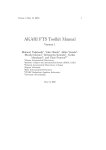
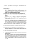
Version 6
User Manual
SUPPLEMENT
© 2006 BRUKER OPTIK GmbH, Rudolf-Plank-Straße 27, D-76275 Ettlingen, www.brukeroptics.com
All rights reserved. No part of this manual may be reproduced or transmitted in any form or by any
means including printing, photocopying, microfilm, electronic systems etc. without our prior written
permission. Brand names, registered trademarks etc. used in this manual, even if not explicitly marked
as such, are not to be considered unprotected by trademarks law. They are the property of their
respective owner.
The following publication has been worked out with utmost care. However, Bruker Optik GmbH does
not accept any liability for the correctness of the information. Bruker Optik GmbH reserves the right to
make changes to the products described in this manual without notice.
This manual is the supplement documentation for OPUS 6.
Table of Contents
Introduction . . . . . . . . . . . . . . . . . . . . . . . . . . . . . . . . . . . . . . . . . . . . . . .1
1
Easy Measurement Mode . . . . . . . . . . . . . . . . . . . . . . . . . . . . . . . . . . . .3
1.1
1.2
1.3
2
Accessories in Measurement Dialog and OVP . . . . . . . . . . . . . . . . . . .9
2.1
2.2
2.3
2.4
2.5
2.6
3
Installation . . . . . . . . . . . . . . . . . . . . . . . . . . . . . . . . . . . . . . . . . . . . . . . . . . . 3
Routine Workspace . . . . . . . . . . . . . . . . . . . . . . . . . . . . . . . . . . . . . . . . . . . . . 4
Switching off Mode . . . . . . . . . . . . . . . . . . . . . . . . . . . . . . . . . . . . . . . . . . . . 6
Accessories in Measurement Dialog . . . . . . . . . . . . . . . . . . . . . . . . . . . . . . . 9
Accessories in OVP . . . . . . . . . . . . . . . . . . . . . . . . . . . . . . . . . . . . . . . . . . . 10
Inserting accessory with activated AAR . . . . . . . . . . . . . . . . . . . . . . . . . . . . 11
Inserting accessory without activated AAR . . . . . . . . . . . . . . . . . . . . . . . . . 12
Special case: ATR Several Crystals . . . . . . . . . . . . . . . . . . . . . . . . . . . . . . . 13
Special case: HYPERION . . . . . . . . . . . . . . . . . . . . . . . . . . . . . . . . . . . . . . 13
Up-dated Information . . . . . . . . . . . . . . . . . . . . . . . . . . . . . . . . . . . . . .15
3.1
3.2
3.3
3.4
3.5
3.6
3.7
Correlation Modes . . . . . . . . . . . . . . . . . . . . . . . . . . . . . . . . . . . . . . . . . . . . 15
AAR Test Result . . . . . . . . . . . . . . . . . . . . . . . . . . . . . . . . . . . . . . . . . . . . . . 16
Rapid Scan Measurement . . . . . . . . . . . . . . . . . . . . . . . . . . . . . . . . . . . . . . . 17
Interleaved Time Resolved Measurement . . . . . . . . . . . . . . . . . . . . . . . . . . 18
Step Scan Measurement . . . . . . . . . . . . . . . . . . . . . . . . . . . . . . . . . . . . . . . . 18
ATR Correction . . . . . . . . . . . . . . . . . . . . . . . . . . . . . . . . . . . . . . . . . . . . . . 18
Spectrum Search . . . . . . . . . . . . . . . . . . . . . . . . . . . . . . . . . . . . . . . . . . . . . . 18
iii
iv
Introduction
This supplement comprises new features designed for the OPUS version 6,
which have not yet been described in the corresponding manuals, as well as updated information on existing OPUS commands.
New Features:
• Easy Measurement Mode: for quality control using MPA and
TENSOR 27 only
• Accessories in measurement and OVP
Up-dated Information:
•
•
•
•
•
•
•
Bruker Optik GmbH
Correlation Modes
AAR Test Result
Rapid Scan Measurement
Interleaved Time Resolved Measurement
Step Scan Measurement
ATR Correction
Spectrum Search
Supplement for OPUS 6
1
2
Supplement for OPUS 6
Bruker Optik GmbH
Installation
1
Easy Measurement Mode
The Easy Measurement mode has been designed for quality control when using
TENSOR 27 and MPA spectrometers. To switch off this mode you need to have
Administrator rights in OPUS.
If you work in this mode, specific parameters are pre-defined and
interferograms will automatically be stored. The Bruker standard experiments
have been adapted to this mode.
1.1
Installation
When installing OPUS follow the on-screen instructions. Make sure that you
select the correct instrument for quality control. Depending on the instrument
used either select:
• TENSOR 27 for quality control or
• MPA
Figure 1: Selecting instrument type during OPUS installation
For further details on the installation procedure refer to the OPUS Installation
Instructions. If the installation has been finished, start OPUS.
Bruker Optik GmbH
Supplement for OPUS 6
3
Easy Measurement Mode
1.2
Routine Workspace
When working in the Easy Measurement mode the respective routine
measurement workspace opens by default. The workspace is defined as:
• MIR_Routine_Quali. ows (in case of TENSOR)
• NIR_Routine_ows (in case of MPA)
The Measure menu as well as all the other OPUS menus, e.g. Manipulate or
Evaluate include only those commands which are required for routine
measurement. Figure 2 exemplifies the Measure menu.
Figure 2: Measure menu in Easy Measure mode
To perform a measurement select the Advanced Measurement command from
the Measure menu. The following dialog opens:
Figure 3: Measurement - Basic tab
4
Supplement for OPUS 6
Bruker Optik GmbH
Routine Workspace
The DEFAULT measurement experiment with parameters specified by Bruker
is automatically loaded. Click on the Load button if you want to load a different
experiment.
If the parameters defined for a user-specific experiment differ from the
parameters specified by Bruker, the following error message pops up:
Figure 4: Error message
This may occur in case of loading existing experiments in the Easy
Measurement mode. Measurements using non-conforming parameters are not
possible, by default.
Note: Before storing the experiment file with the new parameters a backup is
made of the original file (*.xpm.bak). If you work in validated mode, you have to
sign the experiment once again after the experiment file has been stored.
On the Optics tab all registered accessories are displayed (only in case of
TENSOR). Select the appropriate accessory from the drop-down list (A in
figure 5).
If the accessory currently inserted has already been registered, the name of the
this accessory is also displayed (B in figure 5) in the measurement dialog.
Bruker Optik GmbH
Supplement for OPUS 6
5
Easy Measurement Mode
A
B
Figure 5: Measurement - Optic tab
1.3
Switching off Mode
The Easy Measurement mode can only be switched off by the Administrator.
Select the Optic Setup and Service command from the Measure menu and click
on the Devices/Options tab.
6
Supplement for OPUS 6
Bruker Optik GmbH
Switching off Mode
Figure 6: Optic Setup and Service - Devices/Options tab
The Enforced Pre-defined Measurement Parameter check box is automatically
activated if OPUS is installed for the first time to perform measurements by
using MPA or TENSOR. To deactivate the mode remove the check mark.
Bruker Optik GmbH
Supplement for OPUS 6
7
Easy Measurement Mode
8
Supplement for OPUS 6
Bruker Optik GmbH
Accessories in Measurement Dialog
2
Accessories in Measurement Dialog and OVP
Note: Refers to chapter 13 in the OPUS Reference Manual
The following describes the QuickLock accessory recognition in OVP. This
kind of feature is available for TENSOR and VERTEX spectrometer series
only.
2.1
Accessories in Measurement Dialog
If you select the Advanced Measurement command to open the measurement
dialog, a drop-down list is displayed on the Optics tab, which includes all
accessories registered for the respective spectrometer.
Note: For information on how to register accessories by Automatic Accessory
Recognition (AAR) refer to the OPUS AAR manual.
Figure 7: Measurement - Accessory list
The accessory currently inserted into the spectrometer is also shown to the right
of the drop-down list (see figure 5).
If you store a measurement experiment, the accessory selected from the dropdown list will be stored as a parameter. This means that the measurement using
this experiment can only be performed by inserting the correct accessory.
If you load an experiment which uses an accessory not currently inserted into
the sample compartment, the drop-down list field in the measurement dialog is
marked red. In this case no measurement can be performed.
Bruker Optik GmbH
Supplement for OPUS 6
9
Accessories in Measurement Dialog and OVP
2.2
Accessories in OVP
If you have selected any accessory in OVP (A in figure 8) the measurement
configuration, i.e. the combination of source, beamsplitter, measurement
channel and detector, will be extended by this accessory (B).
B
A
Figure 8: Setup OVP
In this case make sure that you measure the laser wavenumber with the
accessory being inserted. The measurement will then recognize the correct test
channel and thus the correct laser wavenumber, depending on the accessory
being inserted.
10
Supplement for OPUS 6
Bruker Optik GmbH
Inserting accessory with activated AAR
2.3
Inserting accessory with activated AAR
Inserting a QuickLock accessory for the first time enables the firmware to
recognize that any accessory exists in the sample compartment. The firmware,
however, cannot recognize the type of accessory and writes a question mark as
type of accessory.
If the Automatic Accessory Recognition (AAR) is activated by means of the
Optic Setup and Service command from the Measure menu, OPUS recognizes
that an unknown type of accessory is in the sample compartment. Use AAR to
exactly define the name and type of the accessory.
Note: AAR only runs if you first have defined a test channel in OVP for the sample compartment. Otherwise, an error message pops up in AAR. Afterwards AAR
sets up a second test channel for the respective accessory type.
When inserting the accessory AAR starts and tries to recognize the type of
accessory by means of a measurement. In case of a non-registered accessory
AAR provides a drop-down list which you use to select a general accessory type
or an accessory which has already been registered in the OVP database.
If you have activated the Accessory has to be tested check box (figure 9), an
OVP test channel is automatically set up for this kind of accessory and a
shortened S/N test (one measurement) performed.
Figure 9: AAR - Accessory to be tested
If you deactivate the check box, no OVP test channel will be set up. Select the
new test channel in OVP for the respective type of accessory.
Figure 10: Setup OVP - Accessory selected
Bruker Optik GmbH
Supplement for OPUS 6
11
Accessories in Measurement Dialog and OVP
Afterwards, click on the Measure LWN button to measure the laser
wavenumber. OVP will then enter the accessory recognition into the test
channel configuration (as defined in AAR). If you perform measurements by
using this type of accessory, the test channel will automatically be recognized
and the correct laser wavenumber used. When inserting a different registered
type of accessory, only the S/N test will be performed OVP.
2.4
Inserting accessory without activated
AAR
In this case the firmware defines all accessories inserted by a question mark in
the optics. Therefore, these types of accessories will neither be recognized by
OVP nor displayed in the measurement dialog (see figure 7).
You have to manually set up a separate OVP channel for this type of accessory.
As soon as you measure the laser wavenumber the name of the accessory
selected in OVP will be used and replaced by this name in the optics. Thus, the
accessory is also displayed in the measurement dialog even if AAR is not
activated.
If you perform a measurement by using this type of accessory, the test channel
will also be automatically recognized and the correct laser wavenumber used.
Note: This feature is only activated for Sample Compartment measurement channels. In case of an external channel (e.g. External Port) the sample compartment
accessory currently inserted for this measurement channel will not be taken into
account.
12
Supplement for OPUS 6
Bruker Optik GmbH
Special case: ATR Several Crystals
2.5
Special case: ATR Several Crystals
In case of ATR accessories with changeable crystals neither the optics nor OVP
recognizes what type of crystal is currently used. This requires a separate OVP
test channel to be set up for every possible kind of crystal.
Select General Type - ATR Several Crystals from the Accessory drop-down list
in OVP for each one of these test channels.
Figure 11: Setup OVP - General Type ATR several crystals
Consequently, the same configuration exists several times in OVP. In case of
several identical configurations OVP always uses the laser wavenumber of the
first configuration found. Tests have shown that the crystal type has an
insignificant influence, if at all, on the laser wavenumber.
Due to the different optical characteristics of crystals you have to measure
reference spectra for each crystal separately to run PQ tests.
2.6
Special case: HYPERION
As Hyperion is no QuickLock accessory it cannot be recognized by the
spectrometer optics. To ensure an OVP accessory assignment OVP writes
accessory information into the optics as soon as the laser wavenumber has been
measured for a Hyperion configuration.
The following kind of information is written into the optics:
• Type of accessory: HYPERION
• Accessory ID: HYPERI01_xx with being xx = IT Channel No (01,
02, 03…)
• Name of accessory: as indicated in the OVP accessory list (e.g.
Hyperion 1000/2000 ATR Objective)
• Accessory location: 0x0
Hyperion configurations are also displayed in the Accessory drop-down list of
the measurement dialog. They are recognized by OVP and assigned to the
correct test channel. This ensures that the correct laser wavenumber is used
when a measurement is performed.
Bruker Optik GmbH
Supplement for OPUS 6
13
Accessories in Measurement Dialog and OVP
14
Supplement for OPUS 6
Bruker Optik GmbH
Correlation Modes
3
Up-dated Information
This chapter includes up-dated information on existing OPUS commands.
3.1
Correlation Modes
Note: Refers to chapter 7.2.5 in the OPUS Reference Manual
The correlation mode determines whether a data integrity check is performed
during data acquisition. Depending on the spectrometer type OPUS provides
different correlation modes.
Spectrometer Type
AQP instruments
Mode
Definition
No
No data check
Around Peak, Low
This mode is only available, if several scans are averaged. Each new interferogram is compared to the first
one within a range around the centerburst. If the deviation exceeds the threshold the interferogram will be
rejected. Otherwise, the interferogram will be used for
averaging.
Around Peak, High Same as Around Peak Low, but the limit is more sensitive to minor changes (e.g. caused by thermal drift in
case of long-term measurements).
AQP instruments with Raman Full Igram Length
All interferogram data points are compared to each
other. An interferogram is rejected if the points contain
more than 10 defective areas or if the number of defective points exceeds one eighth of the total number of
interferogram points.
TENSOR, MATRIX, MPA,
VERTEX, IFS 125HR
OFF
No data check
ADC FS (Full
Scale)
The complete scan is rejected if the inteferogram
amplitude is greater than 80%. If this mode is activated, acquisition and co-addition of overloaded signals is avoided.
Vel (Velocity)
Rejects all scans which velocity deviation is greater
than the specified limit during data acquisition. The
default deviation limit is set to >2% and can be customized.
IFG_Length_Difference
The number of interferogram data points is not identical to the nominal number. This mode should be activated in case of non-frequent and intense mechanical
disturbances to have the scan automatically rejected.
Bruker Optik GmbH
Supplement for OPUS 6
15
Up-dated Information
Spectrometer Type
3.2
Mode
Definition
Signal Amplitude
Limits
Scans of a particular interferogram amplitude range
are used only. The range can be customized.
Start on Signal
Amplitude Limits
The measurement starts only if one scan is within the
defined amplitude limit. Thus, the measurement is triggered by intensity. Example: sample inserted, measurement starts
Stop on Signal
Amplitude Limits
The measurement stops if a scan is beyond the defined
amplitude limit. Example: sample removed, measurement stops
Raman
Detects Raman spikes in the interferogram and substitutes them by other scans of the same measurement. If
more than 10% of the interferogram data points have
to be substituted, the scan will be rejected.
AAR Test Result
The result of the AAR reference tests is also displayed in the AAR dialog.
Figure 12: AAR test result OK
16
Supplement for OPUS 6
Bruker Optik GmbH
Rapid Scan Measurement
Figure 13: AAR test result not OK
3.3
Rapid Scan Measurement
Note: Refers to chapter 7.4 in the OPUS Reference Manual
The Rapid Scan measurement parameters described in chapter 7.4 do not apply
to MATRIX and MPA spectrometers. The description in the OPUS Reference
Manual refers to AQP instruments. In case of TENSOR and VERTEX
spectrometer series the parameters have to be adapted individually. For further
information on typically-used measurement parameters in case of TENSOR and
VERTEX series refer to the separate documentation which can be provided on
request.
Bruker Optik GmbH
Supplement for OPUS 6
17
Up-dated Information
3.4
Interleaved Time Resolved Measurement
Note: Refers to chapter 7.5 in the OPUS Reference Manual
The Interleaved Time Resolved measurement parameters described in chapter
7.5 apply to the IFS 66(v)/S and IFS 120HR spectrometers only.
3.5
Step Scan Measurement
The Step Scan measurement parameters available in OPUS do not apply to
TENSOR, MATRIX, MPA and IFS 125HR spectrometers. The description in
the OPUS Step Scan manual refers to EQUINOX 55 and IFS 66(v)/S. In case of
VERTEX spectrometer series the parameters have to be adapted individually.
For further information on typically-used measurement parameters in case of
VERTEX refer to the separate documentation which can be provided on
request.
3.6
ATR Correction
Note: Refers to chapter 8.24.2 in the OPUS Reference Manual
Load the spectra measured by an ATR unit into the OPUS browser. Make sure
that the spectrum contains no ranges with strong noise. Otherwise, use the Cut
or the Straight Line Generation command from the Manipulate menu to modify
these ranges. As the extended ATR correction is sensitive to noise wrong results
may be produced.
3.7
Spectrum Search
Note: Refers to chapter 9.11 in the OPUS Reference Manual and 2.3.1 in the
OPUS SEARCH manual.
The following search algorithms which can be selected from the drop-down list
on the Search Parameters tab are available in OPUS.
18
Supplement for OPUS 6
Bruker Optik GmbH
Spectrum Search
Figure 14: Spectrum Search - Search Parameters tab
• Standard
All pieces of band information, which are available from the query
and library spectrum, are reflected in the hit quality. The information
contains the position, relative intensity and half-width of each band.
A library spectrum band is considered to be identified in the query
spectrum if this spectrum contains a band
- which position does deviate from the position in the library spectrum by less than the half-width,
- which difference between the half-widths and relative intensities is
less than factor 2, respectively.
This algorithm also allows to further specify the search result. Select
the appropriate option button to define whether the query spectrum
consists of one main component or multiple components.
• Use Existing Peak Table
This algorithm uses an already existing peak table, which enables
you to suppress the influence of peaks originating from the substrate.
Depending on the measurement you can additionally define whether
the spectrum to be searched for contains one component (in case of a
single substance) or multiple components (in case of compounds).
• Spectrum Correlation
This algorithm calculates the sum of the squared deviations between
the query spectrum and the result spectrum for the data points of the
range defined. The summation can be limited to a spectral range
selected by the user. If you use this algorithm, two additional dropdown lists, Normalization Method and Derivative, are displayed.
Bruker Optik GmbH
Supplement for OPUS 6
19
Up-dated Information
20
Supplement for OPUS 6
Bruker Optik GmbH