1
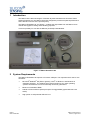
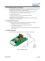
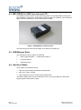
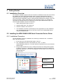
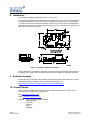
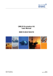
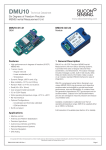
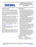
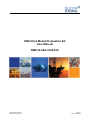
DMU10 (A Model) Evaluation Kit User Manual DMU10-00A-0100-910 DMU10-00A-0100-910 Issue 2, August 2014 Page 1 DCR 710007492 Copyright Statements Document number: DMU10-00A-0100-910 Entitled: DMU10 (A Model) Evaluation Kit User Manual This is an unpublished work created in 2014, any copyright in which vests in Silicon Sensing Systems Limited. All rights reserved. The information contained in this document is proprietary to Silicon Sensing Systems Limited unless stated otherwise and is made available in confidence; it must not be used or disclosed without the express written permission of Silicon Sensing Systems Limited. This document may not be copied in whole or in part in any form without the express written consent of Silicon Sensing Systems Limited which may be given by contract. This document contains commercially-sensitive trade secrets as of the date provided to the original recipient by Silicon Sensing Systems Limited and is provided in confidence. Release of the information to any third party is prohibited without prior written consent from Silicon Sensing Systems Limited. Public authorities are prohibited from releasing the information unless its release would not constitute an actionable breach of confidence. Public authorities should contact Silicon Sensing Systems Limited to determine the current releasability of the information. [5 USC 552(b)(4) and 18 USC 1905]/ [Sections 41 and 43 of the Freedom of Information Act 2000] are applicable. UK Origin Any enquiries relating to this document or its contents should be addressed in the first instance to: Silicon Sensing Systems Limited, Clittaford Road, Southway, Plymouth, Devon PL6 6DE Telephone: Fax: (01752) 723330 (01752) 723331 International: International: +44 1752 723330 +44 1752 723331 Silicon Sensing Systems Limited is a Joint Venture between Atlantic Inertial Systems and Sumitomo Precision Products. Silicon Sensing Systems Limited is the trademark of Page 2 DCR 710007492 DMU10-00A-0100-910 Issue 2, August 2014 CONTENTS Section Page 1 Introduction ....................................................................................................... 6 2 System Requirements ...................................................................................... 6 3 Potential Restrictions and Issues ................................................................... 7 4 Evaluation Kit Contents ................................................................................... 7 4.1 4.2 4.3 4.4 DMU10 (A Model) .......................................................................................................................... 7 MEV RS485i to USB Converter and CD ....................................................................................... 8 USB Memory Stick ........................................................................................................................ 8 Interface Cables ............................................................................................................................ 8 5 Getting Started .................................................................................................. 9 5.1 5.2 Installation Overview ..................................................................................................................... 9 Installing the MEV RS485i USB Serial Converter Device Driver .................................................. 9 5.2.1 Installation Procedure .................................................................................................... 9 5.2.2 MEV Installation Troubleshooting ................................................................................ 11 Installing the Data Logging Software .......................................................................................... 12 5.3.1 Installation Procedure .................................................................................................. 12 5.3.2 Installation Troubleshooting ......................................................................................... 14 Using the Software ...................................................................................................................... 15 5.4.1 Starting the Application ................................................................................................ 15 5.4.2 Main Window ............................................................................................................... 15 5.4.3 Display Tab .................................................................................................................. 17 5.4.4 Logging Tab ................................................................................................................. 17 5.4.5 Settings Tab ................................................................................................................. 22 5.4.6 Changing the MEV 485i Driver Settings ...................................................................... 23 5.3 5.4 6 Using the DMU10 without the Evaluation Kit ............................................... 26 6.1 Sensor Sampling and Synchronisation ....................................................................................... 28 7 DMU10 Electrical Connections ...................................................................... 29 8 Installation ....................................................................................................... 30 9 Software Updates ........................................................................................... 30 10 Contact Details................................................................................................ 30 TABLES Table 1: Operational Message Data Output Descriptions ..........................................................................19 Table 2: Default Settings ............................................................................................................................23 Table 3: Connector Pin Out (A Model) .......................................................................................................26 Table 4: Operational Message Data Output Descriptions ..........................................................................27 DMU10-00A-0100-910 Issue 2, August 2014 Page 3 DCR 710007492 FIGURES Figure 1: DMU10 Evaluation Kit ...................................................................................................................6 Figure 2: DMU10 (A Model) ..........................................................................................................................7 Figure 3: MEV RS485i to USB Converter .....................................................................................................8 Figure 4: Software Application Main Window .............................................................................................15 Figure 5: Main Controls ..............................................................................................................................16 Figure 6: Main Tab Options ........................................................................................................................16 Figure 7: Real-time Display Page ...............................................................................................................17 Figure 8: Logging Tab Overview ................................................................................................................18 Figure 9: Log to memory Tab .....................................................................................................................20 Figure 10: Log to disk Tab ..........................................................................................................................21 Figure 11: Log files in the default log file directory .....................................................................................22 Figure 12: Settings Page ............................................................................................................................22 Figure 13: DMU10 Architecture (A Model) .................................................................................................26 Figure 14: Connection to a Host System ....................................................................................................27 Figure 15: Interface Cable 630486-0900 ....................................................................................................29 Figure 16: Blank Connector for Customer Use...........................................................................................29 Figure 17: Pin 1 of the blank cable connector ............................................................................................29 Figure 18: DMU10 (A Model) Installation ...................................................................................................30 Page 4 DCR 710007492 DMU10-00A-0100-910 Issue 2, August 2014 GLOSSARY CD Compact Disk CD-ROM CD-Read Only Memory COM Serial port interface CSV Comma Separated Variables DMU Dynamic Measurement Unit FP Floating Point GND Ground IMU Inertial Measurement Unit kbit/s kilobits per second LPT Parallel port interface MB Mega Bytes ms milliseconds OEM Original Equipment Manufacturer PC Personal Computer PCB Printed Circuit Board RAM Random Access Memory Rx Receive SP Service Pack Tx Transmit USB Universal Serial Bus Vel Velocity DMU10-00A-0100-910 Issue 2, August 2014 Page 5 DCR 710007492 1 Introduction The DMU10 is the latest six degree of freedom Dynamic Measurement Unit from Silicon Sensing Systems Ltd. The DMU10 has been designed to provide exceptional performance where size and cost are of the upmost priority. The DMU10 Evaluation Kit, see Figure 1, enables the output data from the DMU10 to be viewed and logged for testing and evaluating purposes. This kit is primarily for use with the DMU10 (A Model) build standard. MEV RS485i to USB Converter DMU10 A Model MEV to PC USB 2.0 Cable USB Memory Stick DMU10 to MEV Cable DMU10 Mating Connector Kit with unterminated leads MEV CD containing drivers and MEV user manual Figure 1: DMU10 Evaluation Kit 2 System Requirements The DMU10 Evaluation Kit requires a PC with a USB port. The requirements for the PC are as follows: Microsoft Windows XP (SP3 or greater), Vista or Window 7 and Windows 8 Operating Systems. The software has not been tested on any other operating systems and therefore correct functionality cannot be guaranteed. Minimum of 500 Mb of RAM. 500 Mb of free hard drive space plus space for logged data (typical data rate ≈ 50 kbit/s). High power or self-powered USB 2.0 Port. Page 6 DCR 710007492 ® ® ® DMU10-00A-0100-910 Issue 2, August 2014 3 Potential Restrictions and Issues The USB interface on the PC can result in errors in the USB Message Stream introduced by interruptions by the operating system, resulting in possible loss of partial or complete messages. Such errors, if they occur, can be minimised by: a) Minimising the number of other applications and software running on the PC. b) Disconnecting the PC from a network or wireless connection. c) Using very high speed PCs. d) Disabling scheduled virus scans and Operating System updates. e) Disabling all PC power saving options. Any disruption to the message stream can be observed in the logged files using the message counter, checking for lost data. 4 Evaluation Kit Contents The DMU10 evaluation kit (part number DMU10-21-0500) contains the following: DMU10 IMU A Model, (Part Number DMU10-21-0100) MEV RS485i to USB Converter, (Part Number 630486-0910) CD containing the MEV drivers USB memory stick (Part Number 630486-0920) containing the data logging software Interface Cables 4.1 DMU10 (A Model) Figure 2 shows the Dynamic Measurement Unit used with the evaluation kit. Figure 2: DMU10 (A Model) DMU10-00A-0100-910 Issue 2, August 2014 Page 7 DCR 710007492 4.2 MEV RS485i to USB Converter and CD The RS485i to USB Converter is manufactured by MEV. The standard MEV converter has been modified to route the 5 V USB Supply Voltage through to the DMU10, which allows the DMU10 and the Evaluation Kit to be powered from the USB. Figure 3: MEV RS485i to USB Converter The drivers and user manual for the MEV are included on the MEV CD. 4.3 USB Memory Stick The USB Memory Stick contains the following: Data Logging Software – 1-10670-020-430 Rev 2 This User Manual DMU10 Brochure 4.4 Interface Cables Three cables are included in the kit: 1. DMU10 to MEV Cable (Part Number 630486-0900) 2. MEV to PC USB 2.0 Cable. 3. DMU10 Mating Connector kit with unterminated leads The DMU10 Mating Connector kit enables the user to connect the DMU10 to alternative logging equipment and power supply. Page 8 DCR 710007492 DMU10-00A-0100-910 Issue 2, August 2014 5 Getting Started 5.1 Installation Overview The software installation program uses the ‘ClickOnce’ installation format and can therefore be installed onto a PC without administrator rights. However, administrator rights are required whenever the application connects to an individual MEV device for the first time. This is because the application needs to change the MEV default driver settings, which are stored in the HKEY_LOCAL_MACHINE area of the Windows registry. For subsequent connections to that MEV device, the application will not require administrator rights. The recommended installation sequence is therefore: 1. Obtain administrator rights on the PC. 2. Install the MEV driver, see section 5.2. 3. Install the software, see section 5.3. 4. The installation procedure automatically runs the application once the installation has completed and at this point you should connect to the installed MEV device using the Connect button. 5.2 Installing the MEV RS485i USB Serial Converter Device Driver 5.2.1 Installation Procedure The MEV RS485i includes an installation CD containing a USB driver file. To install the driver, proceed as follows: 1. Ensure that you have administrator rights on the PC. 2. Run <CD ROM Drive letter>:\Drivers\Win XP, Vista, 7, 8, 20032012\CDM20828_Setup.exe. This will install the required drivers into the Windows System folder. 3. Plug the MEV RS485i device into a USB port and when the dialog below appears, be ready to click it or, if it disappears, click the animated icon that it is attached to. Note that in Windows 7, this icon can disappear into the hidden icon box when the dialog disappears. Installing device driver icon Windows 7 hidden icons box DMU10-00A-0100-910 Issue 2, August 2014 Page 9 DCR 710007492 4. When the dialog shown below appears, click Skip obtaining driver software from Windows Update. If the PC has an internet connection, you can wait for the latest driver to be found via Windows Update. In which case you can skip to step 7 of this procedure. Note however that if a newer driver version is loaded, the software may not have been tested with this driver version. 5. Click Yes when the following dialog appears: 6. The following dialog should then appear and you must wait (do not click Close because the installation program has not completed yet): Page 10 DCR 710007492 DMU10-00A-0100-910 Issue 2, August 2014 7. The installation program should then locate the previously installed drivers and you should eventually see the following dialog: 8. Click Close on the above dialog. 5.2.2 MEV Installation Troubleshooting Correctly installed MEV devices should appear in the Windows Device Manager as USB virtual COM ports. These devices will disappear when the USB cable is removed but should re-appear when it is re-inserted. These same COM ports will appear in the DMU10 Utility serial port drop down list, enabling the application to connect to different MEV devices. Note that each MEV device appears as a separate COM port and you will need to repeat steps 3 to 8 of the installation procedure for each MEV device plugged into the PC. If a MEV device appears under the Other devices heading of Device Manager instead of the Ports (COM & LPT) heading, then the device is in the process of being installed and you should not unplug it (look for the Installing Driver icon in the lower icon bar and follow steps 3 to 8 of the installation procedure). DMU10-00A-0100-910 Issue 2, August 2014 Page 11 DCR 710007492 If you encounter problems connecting to a MEV device using the application’s Connect button, it is possible that the installation failed. You can repeat an installation by right clicking on the device under the Ports (COM & LPT) heading and selecting the Uninstall option. When the dialog below appears, click OK. You must then unplug the USB cable and then plug it back in to restart the installation procedure (steps 3 to 8) again. If the MEV is not detected when the USB cable is plugged into the PC, refer to the MEV USB232/485 Instruction Manual included on the CD within the DMU10 Evaluation Kit. Additional information may be also available on the MEV website at http://www.mev.co.uk 5.3 Installing the Data Logging Software The data logging software is included on the USB Memory Stick within the DMU10 Evaluation Kit. This software should work on all supported versions of Windows including XP. 5.3.1 Installation Procedure To install the software, proceed as follows: 1. If a previous version of the Utility has been installed on the PC, you should un-install it first to prevent two different versions appearing. To do this select Control Panel | Programs | Uninstall a program to open the Uninstall or change a program dialog. Left click on the DMU10 program and select Uninstall/Change. Page 12 DCR 710007492 DMU10-00A-0100-910 Issue 2, August 2014 2. Click OK to remove the application from the PC. 3. If you have not already installed the MEV device driver, you should do this now (see section 5.2), and then ensure that the MEV device is plugged into a USB port on the PC. 4. Insert the USB Memory Stick into a USB Port on your PC. Once the memory stick is detected, you should see the following files: 5. Run the Setup.exe program. Depending on how administrator rights are managed on some installations, you may need to select Setup.exe in its folder (it must be highlighted) and then right click and select the Run as administrator option in order to ensure that the installation is run with administrator rights. You may see the following message displayed because the software is proprietary to Silicon Sensing Systems Ltd and has not been registered with Microsoft. 6. Click Install to install the data logging software. DMU10-00A-0100-910 Issue 2, August 2014 Page 13 DCR 710007492 7. The installation should then proceed with the following dialog: Note that this dialog may may be missed because it only appears very briefly on fast PCs. The software will install at the following location: Start | All Programs | Silicon Sensing 8. When the installation has completed, the application will be started by the install program. You should then ensure that a USB Serial Port is selected and then click the Connect button. This will write the required MEV driver settings to the Windows Registry. If you intend to use other MEV devices and do not normally have administrator rights on the PC, you should plug all the MEV devices into the PC now and repeat the connection process to ensure that each device has the correct settings written to the Windows Registry file. The software installation process is now complete. 5.3.2 Installation Troubleshooting If the installation program was run without administrator rights, the application will be unable to write the required settings to the registry when the Connect button is pressed and the dialog below will appear. If this occurs, you should first attempt to uninstall the application and then re-install it (with administrator rights). If you are unable, for any reason, to install the application with administrator rights, then the settings must be changed manually by following the procedure in section 5.4.6. Note however that changing these settings will also require administrator rights. Page 14 DCR 710007492 DMU10-00A-0100-910 Issue 2, August 2014 5.4 Using the Software 5.4.1 Starting the Application Go to Start | All Programs | Silicon Sensing and select DMU10 to launch the application. Note: In Windows 8, the installation will create a DMU10 icon in the Start menu. 5.4.2 Main Window The application’s main window is shown in Figure 4. Common Menu Controls Main Tab Options Example of Main Tab Page Use ‘maximize’ button to run in full screen mode Figure 4: Software Application Main Window DMU10-00A-0100-910 Issue 2, August 2014 Page 15 DCR 710007492 5.4.2.1 Common Controls Connect / Disconnect button opens the currently selected PC COM port. Selects the PC COM port used to communicate with the DMU10. Displays the number of DMU10 output messages lost in the current session. Clicking this control will reset the count to zero. Figure 5: Main Controls Common controls always remain visible and are used by all Tab pages. These controls have tool tips (help text will appear when you hover the mouse cursor over an enabled control). 5.4.2.2 Main Tab Options There are three main tab options: Display Logging Settings Figure 6: Main Tab Options The following sections describe each tab in detail. Page 16 DCR 710007492 DMU10-00A-0100-910 Issue 2, August 2014 5.4.3 Display Tab The Display tab shows the DMU10 output data in real-time using level meters. Displays DMU10 output data in real-time using level meters. Red = +ve Blue = -ve" Figure 7: Real-time Display Page 5.4.4 Logging Tab The Logging tab enables the DMU10 data output to be logged for evaluation purposes. For data logging, you must first connect the application to a MEV USB Serial Port as described in section 5.4.2.1. The Logging tab contains two tabs: Log to memory Log to disk DMU10-00A-0100-910 Issue 2, August 2014 Page 17 DCR 710007492 Enter the number of messages to log. If this box is left blank, the program will log continuously Select this tab to log DMU10 output data to memory. Data is displayed in a data grid with sortable columns. Start / stop logging The application must be connected to a COM port using the Connect button before data can be logged. Select this tab to log DMU10 output data to disk. Displays the start time of the current logging session. Displays the completion percentage for the current logging session.. Displays how many messages have been logged in the current logging session. Indicates the progress of the current logging session. Figure 8: Logging Tab Overview Page 18 DCR 710007492 DMU10-00A-0100-910 Issue 2, August 2014 5.4.4.1 Log File Format The data is logged in a CSV format. This can be imported into an Excel spreadsheet or read ® using MATLAB or other similar analysis tools. Table 1 shows the contents of the message stream sent from the DMU10 Evaluation Kit to the PC. When the File is imported into MS Excel, the Worksheet is formatted with in Columns in accordance with Table 3. The message rate is 200 Hz, therefore the time between each message is 5 ms. Col Data Item Value / Units A Message Message Number. B Time Stamp Date and Time. C Header 0x55AA D Message Count 16 Bit, 0 to 65535 decimal, overflowing. E Axis X Rate 32 Bit Single Precision FP, (˚/s). F Axis X Acceleration 32 Bit Single Precision FP, (g). G Axis Y Rate 32 Bit Single Precision FP, (˚/s). H Axis Y Acceleration 32 Bit Single Precision FP, (g). I Axis Z Rate 32 Bit Single Precision FP, (˚/s). J Axis Z Acceleration 32 Bit Single Precision FP, (g). K Aux Input Voltage 32 Bit Single Precision FP, (volts). L Average IMU Temperature 32 Bit Single Precision FP, (˚C). M Axis X Delta Theta 32 Bit Single Precision FP, (˚). N Axis X Delta Vel 32 Bit Single Precision FP, (m/s). O Axis Y Delta Theta 32 Bit Single Precision FP, (˚). P Axis Y Delta Vel 32 Bit Single Precision FP, (m/s). Q Axis Z Delta Theta 32 Bit Single Precision FP, (˚). R Axis Z Delta Vel 32 Bit Single Precision FP, (m/s). S Axis X BIT Data 0 to 65535 decimal. T Axis Y BIT Data 0 to 65535 decimal. U Axis Z BIT Data 0 to 65535 decimal. V Checksum 16 Bit 2’s Complement of the 16 Bit Sum of the Previous 0-18 data items. Table 1: Operational Message Data Output Descriptions 5.4.4.2 Log to memory This option should be used for short logging sessions where it is useful to view the data onscreen. Logged data can also be saved to disk in CSV format. The LoggingMinAvailableMemorySpaceBytes setting (see Table 2) enables the user to control the remaining memory space limit. DMU10-00A-0100-910 Issue 2, August 2014 Page 19 DCR 710007492 Indicates the available, remaining memory space. When this value falls below the value set for the “LoggingMinAvailableMemorySpaceBytes” setting, logging will stop. Saves the current logging session data as a CSV file. Clears the current logging session from memory. Displays the path and file name of the last saved log file. Displays captured DMU10 output data. Data columns can be sorted by clicking the column header. Opens Windows Explorer, with the last saved log file selected. Figure 9: Log to memory Tab Page 20 DCR 710007492 DMU10-00A-0100-910 Issue 2, August 2014 5.4.4.3 Log to Disk This option should be used for logging large amounts of data. Log files are created automatically, using a sort friendly date-time file name format. Year, month, day, hour, minute, second, millisecond Eg: _2014_03_25_16_40_29.csv The location that log files are stored in can be set by clicking the log file location display box or by editing the LoggingLogFileDirectory setting (section 5.4.5). If the LoggingLogFileDirectory setting is left empty, a default location will be used. The size that a log file is allowed to grow to is set by the LoggingRecordsPerLogFile setting (section 5.4.5). When this size is reached, a new log file is created. The LoggingMinAvailableDriveSpaceBytes setting (section 5.4.5) allows the user to control the remaining drive space limit. Indicates the available, remaining drive space. When this value falls below the value set for the LoggingMinAvailableDriveSpaceBytes setting, logging will stop. Displays DMU10 output data in real-time using level meters. Red = +ve Blue = -ve" Displays the path and file name for the current log file. Log file size is determined by the LoggingRecordsPerLogFile setting. When this size has been reached, a new log file is created. Clicking this box will open a log file directory selection dialog. Opens Windows Explorer, with the current log file directory selected. Figure 10: Log to disk Tab DMU10-00A-0100-910 Issue 2, August 2014 Page 21 DCR 710007492 Figure 11: Log files in the default log file directory 5.4.5 Settings Tab The Settings tab displays application user settings for editing. If you require a setting to become permanent (i.e. persist between DMU10 Utility re-starts) click Save settings. Figure 12: Settings Page Page 22 DCR 710007492 DMU10-00A-0100-910 Issue 2, August 2014 5.4.5.1 Default Settings The following default application settings are used. Setting name and description Default value FlashLoaderUploadDefaultDirectory This setting should be left empty LoggingLogFileDirectory Overrides the default location for storing log files. This can be edited here or set from the “Log to Disk” page using a selection dialog. Leave this setting empty if you want the default location to be used. LoggingMinAvailableDriveSpaceBytes When logging data to disk, logging will stop when the remaining drive space (in bytes) drops to this limit. 100000000 LoggingMinAvailableMemorySpaceBytes When logging data to memory, logging will stop when the remaining memory space (in bytes) drops to this limit. 300000000 LoggingRecordsPerLogFile When the number of records in a log file reaches this limit, a new log file is created. The DMU10 outputs data at 200Hz so the default setting of 60000 will result in a new file every 5 minutes that is approximately 12.5 Mb in size. 60000 Unlock This setting should be left empty. Empty Table 2: Default Settings 5.4.6 Changing the MEV 485i Driver Settings To perform correctly, the DMU10 utility software requires non-default MEV 485i driver settings. The software will attempt to change them if it detects that they are incorrect. If the software cannot change these settings, it will inform the user by displaying a message. If a message like this appears, follow the procedure below to change the settings: DMU10-00A-0100-910 Issue 2, August 2014 Page 23 DCR 710007492 1. Open Windows Device Manager. Instructions for doing this vary between operating systems. In Windows 7, this can be accessed using Start / Control Panel / Hardware and Sound / Device Manager. 2. Open Ports (COM & LPT) 3. Double click the port that requires changing (the COM port that the DMU10 Utility will connect to) Page 24 DCR 710007492 DMU10-00A-0100-910 Issue 2, August 2014 4. Select the Port Settings tab. 5. Click Advanced. If this results in a message informing you that you do not have write privilages for the registry then you must obtain Administrator rights before continuing with this procedure. Otherwise, change the Receive (Bytes) value to 2240 and the Latency Timer (msec) value to 1 (as shown below). 6. Click OK to save these settings. DMU10-00A-0100-910 Issue 2, August 2014 Page 25 DCR 710007492 6 Using the DMU10 without the Evaluation Kit The information in this section is provided to enable the user to use the DMU10 with alternative logging equipment. Figure 13 shows the internal architecture for DMU10 (A Model). Figure 13: DMU10 Architecture (A Model) Table 3 shows the connector pin out for DMU10 (A Model). Note: Pin 1 is the left pin when looking into the connector. Pin Signal Name Signal In / Out 1 5V +5 V dc power supply I 2 GND Power Supply Ground (0V) I 3 Rx_Hi+ Serial digital data input - RS-422 I 4 Rx_Lo- Serial digital data input - RS-422 I 5 Enable/Disable Serial Stream control. I 6 RESET Processor reset (active low). I 7 Sync Pulse Pulse at set sampling point (active high). O 8 Spare Do not connect to. N/A 9 Tx_Hi+ Serial digital data output - RS-422 O 10 Tx_Lo- Serial digital data output - RS-422 O 11 Boot0 Programming control pin I 12 Spare Do not connect to. N/A Table 3: Connector Pin Out (A Model) Page 26 DCR 710007492 DMU10-00A-0100-910 Issue 2, August 2014 A typical connection to a host system is shown in Figure 14. Note that some connections are not essential for correct operation. Figure 14: Connection to a Host System Table 4 describes the format of the data output message for DMU10 (A Model). Item Word Data Item Value / Units 0 0 Header 16 Bit, 0x55AA 1 1 Message Count 16 Bit, 0 to 65535 decimal. 2 2-3 Axis X Rate 32 Bit Single Precision FP, (˚/s). 3 4-5 Axis X Acceleration 32 Bit Single Precision FP, (g). 4 6-7 Axis Y Rate 32 Bit Single Precision FP, (˚/s). 5 8-9 Axis Y Acceleration 32 Bit Single Precision FP, (g). 6 10-11 Axis Z Rate 32 Bit Single Precision FP, (˚/s). 7 12-13 Axis Z Acceleration 32 Bit Single Precision FP, (g). 8 14-15 Aux Input Voltage 32 Bit Single Precision FP, (volts). 9 16-17 Average IMU Temperature 32 Bit Single Precision FP, (˚C). 10 18-19 Axis X Delta Theta 32 Bit Single Precision FP, (˚). 11 20-21 Axis X Delta Vel 32 Bit Single Precision FP, (m/s). 12 22-23 Axis Y Delta Theta 32 Bit Single Precision FP, (˚). 13 24-25 Axis Y Delta Vel 32 Bit Single Precision FP, (m/s). 14 26-27 Axis Z Delta Theta 32 Bit Single Precision FP, (˚). 15 28-29 Axis Z Delta Vel 32 Bit Single Precision FP, (m/s). 16 30 Axis X BIT Data 16 Bit, 0 to 65535 decimal. 17 31 Axis Y BIT Data 16 Bit, 0 to 65535 decimal. 18 32 Axis Z BIT Data 16 Bit, 0 to 65535 decimal. 19 33 Checksum 16 Bit 2’s Complement of the 16 Bit Sum of the Previous 0-18 data items. Table 4: Operational Message Data Output Descriptions DMU10-00A-0100-910 Issue 2, August 2014 Page 27 DCR 710007492 6.1 Sensor Sampling and Synchronisation When the DMU10 Evaluation Kit is not used, it is possible to make use of the ‘Sync Pulse’ output from the DMU10. The Inertial Sensors within DMU10 are all sampled at 1000 Hz. The ‘Sync Pulse’ on the connector is set HIGH at the start of the sampling and returned to LOW when the last Inertial Sensor is sampled. Pulses are therefore seen on the connector at 1000 Hz. The Inertial Sensors measurements are then be filtered with a 2nd order low pass filter, also running at 1000 Hz. The factory default setting for this filter is to have a corner frequency of 100 Hz. The DMU10 message is output at 200 Hz, of every 5th sampling cycle. The sequence is: Cycle 1: Sample Sensors, 2nd order Filter. Cycle 2: Sample Sensors, 2nd order Filter, Calculate Sensor Compensation. Cycle 3: Sample Sensors, 2nd order Filter, Apply Sensor Compensation. Cycle 4: Sample Sensors, 2nd order Filter, Cycle 5: Sample Sensors, 2nd order Filter, Transmit Message. The message is transmitted after the ‘Sync Pulse’ associated with Cycle 5 has returned LOW. The Inertial data included in the message is when the ‘Sync Pulse’ associated with Cycle 3 was HIGH. This enables the external equipment to synchronise with the time when the Inertial Data was valid. The Output Message is output on the RS422 Serial output at 460,800 baud using a nonreturn to zero protocol. Each message contains a start bit (logic 0), 8 data bits and 2 stop bits (logic 1). Page 28 DCR 710007492 DMU10-00A-0100-910 Issue 2, August 2014 7 DMU10 Electrical Connections The interface cable shown in Figure 15 enables the DMU10 to be connected directly to the MEV interface allowing the application to be used immediately. 1 8 9 4 MEV 5 3 2 6 RX_HI RX_LO TX_HI TX_LO +5V GND Enable/Disable 10 9 4 3 DMU10 1 2 5 Figure 15: Interface Cable 630486-0900 If the user has a dedicated communication protocol system they wish to use, the blank connector shown in Figure 16 can be used. +5V GND RX_HI RX_LO Enable/Disable Not Connected RESET Sync Pulse 1 2 3 4 5 6 7 DMU10 8 TX_HI TX_LO 9 10 11 12 Figure 16: Blank Connector for Customer Use The blank connector has all the connections pre-crimped to the mating half of the PCB connector, so it can be easily worked into an existing system if required. Figure 17 highlights pin one on the connector. Figure 17: Pin 1 of the blank cable connector DMU10-00A-0100-910 Issue 2, August 2014 Page 29 DCR 710007492 8 Installation The installation drawing for DMU10 is shown in Figure 18. The (unpackaged) DMU10 is an OEM product supplied as a PCB. It is recommended that it is mounted on spacers or pillars using the four mounting holes provided. For the A Model, 2.7 mm holes are used, designed as clearance holes for 2.5 mm screws. The B Model will have the holes located in the same position but will be 2.3 mm diameter holes, designed as clearance holes for 2 mm screws. Figure 18: DMU10 (A Model) Installation During calibration of the DMU10, alignment is achieved using external reference dowels on two edges of the PCB. These two faces therefore form the Datum for alignment purposes. 9 Software Updates If there has been an update to the software supporting the DMU10 Evaluation Kit, it can be downloaded from the ‘Software’ section of the download library at: http://www.siliconsensing.com/information-centre/downloads-library/ 10 Contact Details If you require any additional information about the DMU10 Evaluation Kit or any other products please contact Silicon Sensing via: Web: www.siliconsensing.com Email: [email protected] Address: Page 30 DCR 710007492 Silicon Sensing Systems Limited Clittaford Road Southway Plymouth Devon PL6 6DE DMU10-00A-0100-910 Issue 2, August 2014 This is the final page of this document DMU10-00A-0100-910 Issue 2, August 2014 Page 31 DCR 710007492