1
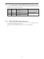
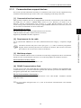
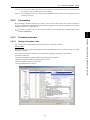
Chapter 5 RUNNING THROUGH RS-485 COMMUNICATION This chapter describes an overview of inverter operation through the RS-485 communications facility. Refer to the RS-485 Communication User's Manual (MEH448b) for details. Contents 5.1 Overview on RS-485 Communication ........................................................................................................ 5-1 5.1.1 RS-485 common specifications (standard and optional)..................................................................... 5-2 5.1.2 RJ-45 connector pin assignment for standard RS-485 communications port...................................... 5-3 5.1.3 Pin assignment for optional RS-485 Communications Card............................................................... 5-4 5.1.4 Cable for RS-485 communications port.............................................................................................. 5-4 5.1.5 Communications support devices........................................................................................................ 5-5 5.2 Overview of FRENIC Loader ..................................................................................................................... 5-6 5.2.1 Specifications ...................................................................................................................................... 5-6 5.2.2 Connection .......................................................................................................................................... 5-7 5.2.3 Function overview............................................................................................................................... 5-7 5.2.3.1 Setting of function code .............................................................................................................. 5-7 5.2.3.2 Multi-monitor.............................................................................................................................. 5-8 5.2.3.3 Running status monitor ............................................................................................................... 5-9 5.2.3.4 Test-running .............................................................................................................................. 5-10 5.2.3.5 Real-time trace—Displaying running status of an inverter in waveforms ................................ 5-11 5.1 Overview on RS-485 Communication 5.1 Overview on RS-485 Communication Detaching the standard keypad from the FRENIC-Multi inverter and using the standard RJ-45 connector (modular jack) as an RS-485 communications port brings about the following enhancements in functionality and operation: Remote operation from a keypad at the remote location Using an extension cable to connect the standard keypad or an optional multi-function keypad to the RJ-45 port allows you to mount the keypad on a panel located far from the inverter, enabling remote operation. The maximum length of the extension cable is 20 m. Operation by FRENIC Loader Control via host equipment Protocols for managing a network including inverters include the Modbus RTU protocol (compliant to the protocol established by Modicon Inc.) that is widely used in FA markets and the Fuji general-purpose inverter protocol that supports the FRENIC-Multi and conventional series of inverters. Connecting the keypad automatically switches to the keypad protocol; there is no need to modify the function code setting. When using FRENIC Loader, which requires a special protocol for handling Loader commands, you need to set up some communication function codes accordingly. For details, refer to the FRENIC Loader Instruction Manual (INR-SI47-0903-E). Further, another RS-485 communications port can be added by mounting an optional RS-485 Communications Card onto the FRENIC-Multi inverter. This additional communications link can be used only as a port for host equipment, not used for a keypad or FRENIC Loader. For details of RS-485 communication, refer to the RS-485 Communication User's Manual (MEH448b). 5-1 RUNNING THROUGH RS-485 COMMUNICATION You can use a personal computer (PC) or a PLC as host (higher-level) equipment and through it control the inverter as its subordinate device. Chap. 5 The Windows-based PC can be connected to the standard RS-485 communications port via a suitable converter. Through the RS-485 communications facility, you may run FRENIC Loader on the PC to edit the function code data and monitor the running status information of the inverter. 5.1.1 RS-485 common specifications (standard and optional) Items Specifications Protocol FGI-BUS Modbus RTU Loader commands (supported only on the standard version) Compliance Fuji general-purpose inverter protocol Modicon Modbus RTU-compliant (only in RTU mode) Dedicated protocol (Not disclosed) No. of supporting stations Host device: 1 Inverters: Up to 31 Electrical specifications EIA RS-485 Connection to RS-485 RJ-45 connector (standard) or terminal block (optional) Synchronization Asynchronous start-stop system Transmission mode Half-duplex Transmission speed 2400, 4800, 9600 19200 or 38400 bps Max. transmission cable length 500 m No. of logical station addresses available 1 to 31 1 to 247 1 to 255 Message frame format FGI-BUS Modbus RTU FRENIC loader Frame synchronization SOH (Start Of Header) character detection Detection of no-data transmission time for 3-byte period Start code 96H detection Frame length Normal transmission: 16 bytes (fixed) Variable length Variable length Write: 50 words Read: 50 words Write: 41 words Read: 41 words High-speed transmission: 8 or 12 bytes Max. transfer data Write: 1 word Read: 1 word Messaging system Polling/Selecting/Broadcast Command message Transmission character format ASCII Binary Binary Character length 8 or 7 bits (selectable by the function code) 8 bits (fixed) 8 bits (fixed) Parity Even, Odd, or None (selectable by the function code) Even (fixed) Stop bit length 1 or 2 bits (selectable by the function code) No parity: 2 bits/1 bit Even or Odd parity: 1 bit Select by parity setting. 1 bit (fixed) Error checking Sum-check CRC-16 Sum-check 5-2 5.1 Overview on RS-485 Communication 5.1.2 RJ-45 connector pin assignment for standard RS-485 communications port The port designed for a standard keypad uses an RJ-45 connector having the following pin assignment: Pin Signal name Function Remarks Vcc Power source for the keypad 5V power lines 2 and 7 GND Reference voltage level Grounding pins 3 and 6 NC Not used. No connection 4 DX- RS-485 data (-) 5 DX+ RS-485 data (+) Built-in terminating resistor: 112Ω Open/close by SW3* * For details about SW3, refer to "Setting up the slide switches" in Section 8.3.1 "Terminal functions." Do not connect the FVR-E11S series of inverters since the pin assignment of the keypad is different from that of the FRENIC-Multi series. Doing so could result in an inverter damage. 5-3 RUNNING THROUGH RS-485 COMMUNICATION Pins 1, 2, 7, and 8 on the RJ-45 connector are exclusively assigned to power supply and grounding for keypads. When connecting other devices to the RJ-45 connector, take care not to use those pins. Failure to do so may cause a short-circuit hazard. Chap. 5 1 and 8 5.1.3 Pin assignment for optional RS-485 Communications Card The RS-485 Communications Card has two RJ-45 connectors for multi-drop connection. Each RJ-45 connector has the pin assignment as listed below. Pin Signal name Function Remarks 1, 3, 6, 7 and 8 NC No connection (Reserved for keypad power source.) — 2 SD Shield terminal Internally connecting SDs 4 DX- RS-485 data (-) 5 DX+ RS-485 data (+) Built-in terminating resistor: 112Ω Open/close by SW9* * For details about SW9, refer to RS-485 User's Manual (MEH448b). 5.1.4 Cable for RS-485 communications port For connection with the RS-485 communications port, be sure to use an appropriate cable and a converter that meet the applicable specifications. For details, refer to the RS-485 Communication User's Manual (MEH448b). 5-4 5.1 Overview on RS-485 Communication 5.1.5 Communications support devices This section provides information necessary for connection of the inverter to host equipment having no RS-485 communications port such as a PC or for configuring a multi-drop connection. [ 1 ] Communications level converter Most personal computers (PC) are not equipped with an RS-485 communications port but RS-232C and USB ports. To connect a FRENIC-Multi inverter to a PC, therefore, you need to use an RS-232C—RS-485 communications level converter or a USB—RS-485 interface converter. For correct running of the communications facility to support FRENIC-Multi series of inverters, be sure to use one of the recommended converters listed below. KS-485PTI (RS-232C—RS-485 communications level converter) USB-485I RJ45-T4P (USB—RS-485 interface converter) Supplied by SYSTEM SACOM Corporation. Use an off-the-shelf 10BASE-T LAN cable (ANSI/TIA/EIA-568A category 5 compliant, straight type). The RJ-45 connector has power source pins (pins 1, 2, 7 and 8) exclusively assigned for keypads. When connecting other devices to the RJ-45 connector, take care not to use those pins. Failure to do so may cause a short-circuit hazard. [ 3 ] Multi-drop adapter To connect a FRENIC-Multi inverter to a network in a multi-drop configuration with a LAN cable that has RJ-45 as the communications connector, use a multi-drop adapter for the RJ-45 connector. Recommended multi-drop adapter Model MS8-BA-JJJ made by SK KOHKI Co., Ltd. [ 4 ] RS-485 Communications Card To equip your inverter with another RS-485 communications port in addition to the standard RS-485 communications port, you need to install this optional card. Note that you cannot use FRENIC Loader through the optional RS-485 communications port. RS-485 Communications Card (option) For details, refer to the RS-485 Communications Card "OPC-E1-RS" Installation Manual (INR-SI47-1089). For more details through Section 5.1.5, refer to the RS-485 Communication User's Manual (MEH448b). 5-5 RUNNING THROUGH RS-485 COMMUNICATION [ 2 ] Requirements for the cable Chap. 5 Recommended converters 5.2 Overview of FRENIC Loader FRENIC Loader is a software tool that supports the operation of the inverter via an RS-485 communications link. It allows you to remotely run or stop the inverter, edit, set, or manage the function codes, monitor key parameters and values during operation, as well as monitor the running status (including alarm information) of the inverters on the RS-485 communications network. 5.2.1 For details, refer to the FRENIC Loader Instruction Manual (INR-SI47-0903-E). Specifications Item Specifications (White on black indicates factory default) Name of software FRENIC Loader Ver. 4.0.0.0 or later Supported inverter FRENIC-Multi series FRENIC-Eco series FRENIC-Mini series Up to 31 Recommended cable 10BASE-T cable with RJ-45 connectors compliant with EIA568 Transmission requirements Operating environment No. of supported inverters Remarks (Note 1) CPU Intel Pentium III 600 MHz or later (Note 2) OS Microsoft Windows 2000 Microsoft Windows XP Memory 32 MB or more RAM Hard disk 5 MB or more free space COM port RS-232C or USB Conversion to RS-485 communication required to connect inverters Monitor resolution XVGA (800 x 600) or higher 1024 x 768, 16-bit color or higher is recommended COM port COM1, COM2, COM3, COM4, COM5, COM6, COM7, COM8 PC COM ports assigned to Loader Transmission rate 38400, 19200, 9600, 4800 and 2400 bps 19200 bps or more is recommended. (Note 3) Character length 8 bits Prefixed Stop bit length 1 bit Prefixed Parity Even Prefixed No. of retries None or 1 to 10 No. of retry times before detecting communications error Timeout setting (100 ms, 300 ms, 500 ms), (1.0 to 9.0 s) or (10.0 to 60.0 s) This setting should be longer than the response interval time set by function code y09 of the inverter. 64 MB or more is recommended (Note 1) FRENIC Loader cannot be used with inverters that do not support SX protocol (protocol for handling Loader commands). With special order-made inverters, FRENIC Loader may not be able to display some function codes normally. To use FRENIC Loader on FRENIC-Mini series of inverters, an RS-485 Communications Card (Option: OPC-C1-RS) is required. 5-6 5.2 Overview of FRENIC Loader (Note 2) Use a PC with as high a performance as possible, since some slow PCs may not properly refresh the operation status monitor and Test-run windows. (Note 3) To use FRENIC Loader on a network where a FRENIC-Mini inverter is also configured, choose 19200 bps or below. 5.2.2 Connection By connecting a number of inverters to one PC, you can control one inverter at a time or a number of inverters simultaneously through multiple windows on the PC. You can also simultaneously monitor multiple inverters on a single screen. For how to connect a PC to one or more inverters, refer to the RS-485 Communication User's Manual (MEH448b). 5.2.3.1 Setting of function code You can set, edit, and check the setting of the inverter’s function code data. List and Edit In List and edit, you can list and edit function codes with function code No., name, set value, set range, and factory default. You can also list function codes by any of the following groups according to your needs: • Function code group • Function codes that have been modified from their factory defaults • Result of comparison with the settings of the inverter • Result of search by function code name • User-specified function code set 5-7 RUNNING THROUGH RS485 COMMUNICATION (OPTION) Function overview Chap. 5 5.2.3 Comparison You can compare the function code data currently being edited with that saved in a file or stored in the inverter. To perform a comparison and review the result displayed, click the Comparison tab and then click the Compared with inverter tab or click the Compared with file tab, and specify the file name. The result of the comparison will be displayed also in the Comparison Result column of the list. File information Clicking the File information tab displays the property and comments for identifying the function code editing file. (1) Property Shows file name, inverter model, inverter’s capacity, date of readout, etc. (2) Comments Displays the comments you have entered. You can write any comments necessary for identifying the file. 5.2.3.2 Multi-monitor This feature lists the status of all the inverters that are marked "connected" in the configuration table. Multi-monitor Allows you to monitor the status of more than one inverter in a list format. 5-8 5.2 Overview of FRENIC Loader 5.2.3.3 Running status monitor The running status monitor offers four monitor functions: I/O monitor, System monitor, Alarm monitor, and Meter display. You can choose an appropriate monitoring format according to the purpose and situation. I/O monitor Allows you to monitor the ON/OFF states of the digital input signals to the inverter and the transistor output signals. Chap. 5 Allows you to check the inverter’s system information (version, model, maintenance information, etc.). Alarm monitor The alarm monitor shows the alarm status of the selected inverter. In this window you can check the details of the alarm currently occurs and related information. Meter display Displays analog readouts of the selected inverter (such as output frequency) on analog meters. The example on the right displays the reference frequency and the output frequency. 5-9 RUNNING THROUGH RS485 COMMUNICATION (OPTION) System monitor 5.2.3.4 Test-running The Test-running feature allows you to test-run the motor in "Run forward" or "Run reverse" while monitoring the running status of the selected inverter. Select monitor item Select what is to be displayed here from output frequency, current, etc. Setting frequency command Enter or select the set frequency command to write it into the inverter. Click Apply to make it effective. I/O terminal status Shows status of the programmable I/O terminals of the inverter. Indicating Operation status Shows FWD, REV, STOP and Alarm codes. Operation buttons* Selecting monitor item Select the operation status information to be monitored real-time. Update the inverter info for the latest ones Click the Refresh button to update running status of the inverter shown on the Loader screen. Loader will become to show the latest inverter status. Switching frequency and run command sources Select the frequency and run command sources and apply them by clicking Apply. * Refer to the table shown below for details of the operation buttons. The indented appearance of the FWD button as shown in the figure above indicates that it is active for running the motor forward, while that of the REV button is same for running reverse. Button Description STOP Stops the motor. FWD Run the motor forward. REV Run the motor reverse. RESET Resets all alarm information saved in the selected inverter. 5-10 5.2 Overview of FRENIC Loader 5.2.3.5 Real-time trace—Displaying running status of an inverter in waveforms This function allows you to monitor up to 4 analog readouts and up to 8 digital ON/OFF signals (a combined total of 8 channels), measured at fixed sampling intervals of 200 ms, which represent the running status of a selected inverter. These quantities are displayed in real-time waveforms on a time trace. Waveform capturing capability: Max. 15,360 samples/channel Sub-panes Set up the monitor items Position graph Status of monitoring Cursor position Save Data Hardcopy the monitor Cursor scroll slide Blinks during the real-time trace running Chap. 5 RUNNING THROUGH RS485 COMMUNICATION (OPTION) START/STOP the real-time trace. Monitoring items of the channels Advanced setting of the channels Scope scroll slide Cursor Monitor window During the trace in progress you cannot: • Change the RS-485 station address, • Change the advanced waveform settings, or • Scroll the real-time trace screen or move the cursor. Resizing the real-time trace window automatically changes the monitor window size. 5-11