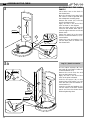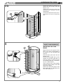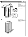
1
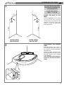
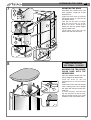
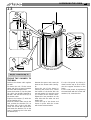
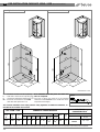
GB PRE-INSTALLATION CARD ART. 122W - 122R (mm 1010 x 810)
Right-side Model
Left-side Model
85
0
0
85
00
10
10
0
00
72
0
2200
2200
72
82
0
0
80
380
380
1800
1800
82
80
65
0
0
0
10
10
10
65
10
0
81
0
81
10
10
0
Measurements in mm.
C
F
O
CA
-
Hot water connection for 1/2" tap fittings
Cold water connection for tap fittings 1/2"
Connection for drainage pipe recessed in floor 1 1/2"
Electrical connection for sauna IPX4
(box with cable press PG 13.5)
N.B. Installation must take place once floors and
Siphon
walls are completed.
The room in which the sauna is to be installed
should be at least 230 cm for the model that can be
inspected at this height).
O
The electrical installation must comply with the safety regulations for bathroom installation, as
described in the enclosed user’s manual.
ART. 122W - 122R
ELECTRICAL
CHARACTERISTICS (1)
HYDRAULIC CHARACTERISTICS
Multifunctions
Net
Weight
Kg.
Delivery
Weight
Kg.
Delivery
Volume
m3
Vertical
Jets
Back
jets
123
155
2,24
6
3
Foot Central
jets Showerh.
2
1
Sauna
Capacity
l/min
Pressure
Min. Max
Pressure
Min. Max
9 ÷ 16
2÷5
bar
0.5 ÷ 5
bar
Supply
Drain
Conn.
1/2"
1
1/2"
Sauna and Multifunctions
Art.
Kw
Min. Max
2MEX18
2NEX18
1,9 ÷ 2,3
(1) - Before connecting the appliance, make sure that the voltage indicated on the rating plate is the same as that of the electric mains.
The information and characteristics shown do not bind Teuco Guzzini Spa who reserves the right to make any modifications it retains necessary without any prior warning or notice of replacement.
18
ASSEMBLING THE CABIN GB
1
All screws and accessories which
are necessary for installation are
in the appropriate box
Bag (A) with screws for
steps 1 - 3 - 3a - 3b
0
57
0
FIXING THE UNIT TO THE
WALL
2050
INSTALLATION
ON THE RIGHT
2
Drill the appropriate hole for fixing
the unit to the wall using the
measurements indicated in the
diagram and then fasten the
bracket (P) with the appropriate
screw and fischer.
P
2050
P
57
INSTALLATION
ON THE LEFT
POSITIONING THE SHOWER
BASE
Place the bathtub in the corner of
the bathroom and make sure it is
on a level by using the appropriate
adjustable feet.
Prepare the drain connection using
the trap supplied with the hose for
the drain (position it as indicated
in the diagram).
N.B.: The unit must be installed after the floor and walls have been finished.
19
GB ASSEMBLING THE CABIN
3
ASSEMBLING THE BACK
PANELS
C1
A
M5X20
Ø5
C
C
4,2x60
Ø5
3a
Bag (C) - plastic accessories
M3x8
Ø4
C2
M
B
C1
C1
M5X20
Ø5
4,2x60
Ø5
20
Place drain cover on the drain in
the shower base.
Move the shower base away from
the corner in order to proceed with
the subsequent assembly steps.
Remove the screws (C1) from the
end of the bottom track.
Apply silicone to the end of the
track as shown in the diagram.
Place the back panel (A) with the
seat onto the shower base and insert the support onto the end of the
bottom track.
Fasten the panel (A) to the track
with the screw and washer (C1) removed earlier.
Insert the screw and washer (C1)
into the back panel to fasten it to
the shower base.
C
A
Fit the rubber doorstop (M) onto
the panel (B) and fasten it with the
screw and washer (C3).
Remove the screw from the end
piece on the bottom track.
Apply silicone to the end of the
track at the point indicated.
Position the panel (B) on the
shower base and fasten it to the
track with the screw and washer removed earlier (C).
Insert the screws and washers (C1)
into the frame of the back shower
panel and into the shower base
without tightening them.
ASSEMBLING THE CABIN GB
3b
Fasten the panels (A) and (B) together with the screws, nuts and
washers (C3).
Tighten the screws (C1) which have
already been inserted into the
shower base.
Consult the attached manual for instructions on how to install the
taps.
M5
Ø5
C3
B
M5x25
Ø5
A
C1
C1
C1
4
Bag (A) - screws for phases 4-5
B
INSTALLING THE SIDE
PANEL
C
C
M5
Ø5
B1
Apply silicone to the groove in the
track in the area corresponding to
the position of the side panel and
end cap.
Slide the side panel (B1) into the
bottom track.
Position the threaded pins on the
support for the side panel (B1) so
that they match up with the holes
on the back panel (B); if necessary,
use a 2.5 Allen wrench.
Check that the seal (!) fits properly
along the entire length of the side
panel (B1) support.
Fasten the side panel (B1) to the
back panel (B) by tightening the
nuts with washers (C).
21
GB ASSEMBLING THE CABIN
5
INSTALLING
TRACK
TOP
Remove the screws from the ends
of the top track.
Insert the track onto the ends of
the supports and fasten it to the
back panels using the screws and
washers (C) that were removed earlier.
Tighten the screws on the ends of
the side panel support (B1), as indicated in the diagram.
C
C
4,2x60
Ø5
4,2x60
Ø5
THE
C
B1
6
22
APPLYING SILICONE
Apply a NEUTRAL (NON ACETIC)
silicone so as to prevent water from
leaking between the back panel
and the bathtub.
ASSEMBLING THE CABIN GB
7
MOUNTING THE DOOR
C
D
N
V
Y
Assemble the handles onto the
door supports, using the screws
provided (C3).
Insert the track cover (V) and the
finish end pieces (Y) into the top
and bottom tracks.
Turn the nut (D) until it is flush
with the top of the (C) screw.
Mount the door, hooking the
wheels (P) with the spring support
onto the lower track
Lift the door up so that the top
wheels (N) slide into the track.
M4x30
V
C3
Y
P
Y
V
8
ONLY FOR ARTICLES
122 STEAM - 122 EASY
MOUNTING THE TWO-CLIMATE
SAUNA DOME UNTO THE
SHOWER CABIN
M5x45
C
G
G
Place the adhesive steam seal onto
the top edge of the back panels.
Insert the screw (C) into the
appropriate hole on the back shower
panel.
Position the sauna onto the shower
cabin, making sure not to damage
the water and electrical hoses attached to it.
To center the sauna, insert the front
flap into the groove on the top track,
making sure that the seal (G) is turned
toward the inside of the shower cabin.
23
GB CONNECTIONS FOR VARIOUS MODELS
Art. 122R (EASY) - Easy Multifunction Shower Box with 2 Climates Steam Sauna
A4
N Blue
Yellow-Green
P Brown
CA
A1
2
9
1
5
4
D
A5
1
2
5
A2
8
D
10
4
D
10
8
A6
3
8
3
D
3
Once the plugs (D) have been
removed, they should not be used
again.
C - Hot water connection.
Use a 90 cm flexible stainless
steel hose.
F - Cold water connection.
Use a 90 cm flexible stainless
steel hose.
A1 - Connection for hoses 1 and 2 for
the sauna unit and for hose 5 for
the shower head with nebulizer.
A2 - Connection for hose 8 for the
vertical massage and for hose 10
for the back massage.
A3 - Cleaning of the taps with filter.
A4 - Connection
between
the
electrical cable coming from the
dome and cable coming from the
power unit.
A5 - Connection for hose 4 (boiler).
24
A6 - Connection for hose 3 (drainage).
N.B.: Hoses 1 and 2 for the
decalcification system must always be
filled with water. Therefore, this
system must not be emptied during
installation.
CA - Electrical connection for the
IPX4 sauna (box with PG13.5
cable clamp ).
F
C
A3
10
CONNECTIONS FOR VARIOUS MODELS GB
10
ONLY FOR ARTICLES
122 STEAM - 122 EASY
EQUIPOTENTIAL EARTHING
CONNECTION
Connect the metal parts of the cabin with the yellow wire as indicated in the diagram.
There is a terminal at point (7) for
the equipotential connection of the
other grounds present in the room.
N.B.:If one of the components indicated in the diagram is not present
on the model purchased, insulate
the corresponding “fast on”.
2
3
4
5
6
7
8
1
FAST ON INSULATED
2
EMERGENCY TAP (ART. 122 EASY)
3
SHOWER SUPPORT ROD
4
SHUT-OFF VALVE FOR THERMOSTATIC MIXER
5
MIXER OR THERMOSTATIC MIXER
6
DIVERTER
7
FRAME FOR BACK PANEL WITH TAPS
8
FRAME FOR BACK PANEL WITH SEAT
25
GB ASSEMBLING THE CABIN
11
USING THE SHOWER FOR
THE FIRST TIME
Once all of the connections are
made and before fastening the cabin to the wall, remove all of the
adhesive tags.
Run the regeneration and a sauna
cycle, following the instructions
contained in the attached user’s
manual.
Make sure that there are no water
leaks in the connections made and
that everything operates normally.
ONLY FOR ARTICLES
122 STEAM - 122 EASY
If there is no power to the sauna
system after the electrical connection has been made to the mains,
press the red button on the power
unit box.
If the control panel displays an error message (all the leds will blink)
the first time the sauna system is
turned on, remove the grate and
press the button for resetting the
thermostat, indicated with the arrow.
12
FITTING THE INSPECTION
DOOR
K
D
26
Position the shower cabin against
the wall.
Close the door and make sure that
the magnetic seals are aligned along
the entire length of the door.
In the event that the seals do not
come together - as in case (A) or
case (B) - adjust the top slide
assembly indicated by the arrow.
- Lift the door, grasping it by the
supports.
- Tighten the screw (D) until the
magnetic seals are aligned.
N.B. After adjusting the slide
assembly, lock the nuts (D) in place,
inserting the covers (K) with the
inner wings facing outwards.
ASSEMBLING THE CABIN GB
13
C4
M5x20
M5-Ø5
C3
C
C4
C1
M5x20
M5-Ø5
M5
Ø5
C2
T1
M5
Ø5
M5x16
Ø5-M5
C2
C
T
P
C5
4,2x38
Ø5
Bag (B) - screws for step 13
FIXING THE SHOWER TO
THE WALL
Position the shower cabin against
the wall.
To fasten the unit, lift the sauna
dome and place a spacer between
the track and the dome itself.
Insert the bracket (T) into the plate
(P), which has already fastened to
the wall, and onto the screw (C) on
the shower cabin.
Tighten the bracket (T) with the
nut and washer (C2).
Move the shower cabin next to the
wall, position the bracket (T1) on
the frame, drill a hole in the wall,
insert the screw with the fischer
and fasten the bracket (T1) to the
frame, tightening the screw with
the washer (C1).
Remove the spacer and center the
dome on the shower cabin (see fig.
8).
Open the top of the dome by
removing the screws (C3); fasten
the bottom of the dome with the
nut and washer (C2) onto the screw
(C) located on the shower cabin.
Repeat this last procedure on the
other side with the other nut and
washer (C4).
Close the top of the dome and
fasten in place with the screws
which were removed earlier.
Fit the side panel by sliding it
down from the top so as to hook it
onto the support brackets on the
frame.
Fix the side panels by tightening
the towel-knob with the screws and
washers (C3); insert the trim.
27